Common Fitment Steering Alignment After Lift Kit for ECU Flash and How to Overcome Them
After you lift your vehicle, expect toe, camber, and caster shifts that change steering feel and bump steer. ECU flashes alter torque bursts and throttle response, which can amplify steering load changes under load and cornering. Use a data-driven workflow: verify sensor data, compare to modeled geometry, and check real-world measurements for drift. Symptoms like steering pull or vague front-end feel signal misalignment. Correct by restoring target camber/toe within specs and recheck after torque-turve changes—more details ahead.
Steering Geometry Shifts After Lifting: Understanding the Basics
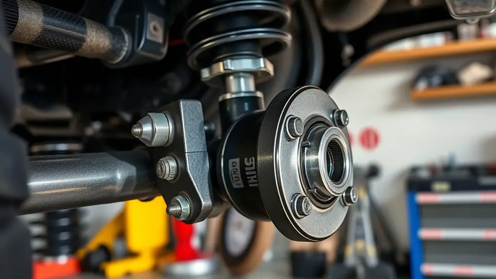
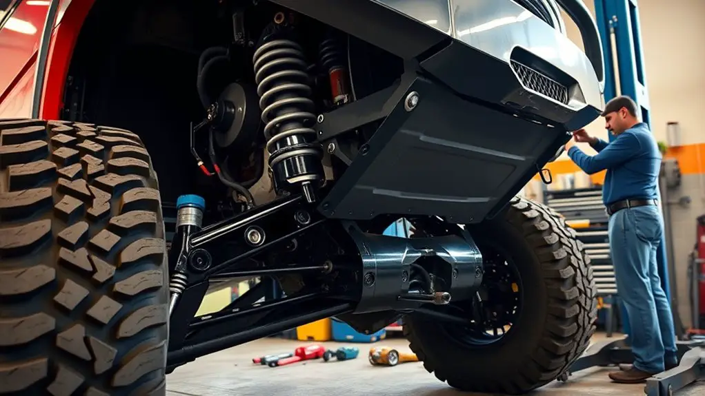
After lifting, steering geometry shifts primarily due to changes in ride height, track width, and suspension articulation, which alter toe, camber, and caster angles. You’ll notice steering dynamics respond as lift effects modify load paths, axle geometry, and contact patch behavior. In practice, higher ride height raises roll center interaction with wheel camber, increasing toe-out tendencies at quick steering inputs and altering self-aligning torque. Track width changes broaden the lateral moment arms, influencing understeer or oversteer tendencies depending on spring rates and anti-dive characteristics. Suspension articulation redefines knuckle geometry, affecting steering ratio feel and bump steer susceptibility. Data-driven assessment uses chassis simulations to map deflections across load cases, identifying critical regions where steering effort and feedback shift. Understanding these baseline shifts enables targeted alignment strategies, such as slight camber correction, toe adjustments, and caster tuning, to preserve predictable steering dynamics while embracing lift effects without compromising control.
How ECU Flashes Can Affect Steering Feel and Response
ECU flashes don’t just alter engine mapping—they also modify steering feel and response indirectly by changing torque delivery, throttle-induced loadpaths, and transient chassis behavior. When you pursue ECU tuning, you’re not only chasing power or fuel economy; you’re shifting the dynamic relationship between drivetrain torque and steering loads. Higher torque bursts at certain RPM bands can tighten or loosen steering feel, altering feedback latency and weight perception at the wheel. Transient fuel/ignition changes change throttle response, which propagates through suspension geometry and tire slip modes, affecting steering calibration needs. In simulations, small gains in torque authority often produce measurable changes in steering toe stiffness and steering angle rate during rapid throttle applications. Data-driven testing shows that steering calibration must account for lift-induced geometry shifts and revised loadpaths to preserve linearity and predictability. You should integrate ECU tuning impacts into alignment planning, prioritizing repeatable steering metrics across speed bands and operating modes.
Diagnosing Alignment Issues Resulting From Lifted Suspension
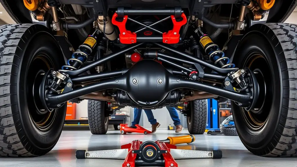
You’ll start by correlating observed Alignment Symptoms After Lift with suspension geometry changes, using quantified metrics from simulations to set baseline tolerances. Next, apply Diagnostics for Lifted Suspension to identify whether camber, toe, or caster shifts exceed expected ranges under load, then flag outliers with data-driven thresholds. Finally, implement a repeatable workflow that cross-validates sensor data, modeled responses, and real-world measurements to guide corrective strategies.
Alignment Symptoms After Lift
Have you noticed steering pull or uneven tire wear after lifting your suspension? In this section, you’ll pinpoint alignment symptoms through a data-driven lens. Alignment indicators appear as asymmetric toe or camber shifts under load, noticeable wobble at highway speed, and late or early return to straight after turns. Lift impacts alter scrub radius, bump-steer tendencies, and caster balance, creating measurable deviations in steering feedback. You’ll rely on simulations and high-precision measurements to quantify lateral tire footprint changes, steering column torque, and dynamic camber variations across suspension cycles. Expect symptoms to correlate with ride height, axle geometry, and wheel offset. This is about recognizing patterns, not guesses, so you can forecast corrective requirements before ECU reflash and ascertain stable, freedom-oriented handling.
Diagnostics for Lifted Suspension
When diagnosing alignment issues in lifted suspensions, start with a structured data-driven approach: collect high-precision measurements of toe, camber, and caster under static load and during dynamic cycles, then correlate changes with ride height, axle geometry, and wheel offset. You’ll build a calibration map that flags outliers and drift, enabling targeted interventions. Use lifted diagnostics to quantify how each parameter shifts with suspension articulation, bump stops, and steering geometry, then validate changes with repeat cycles and cross-checks against manufacturer tolerances. Prioritize suspension calibration as the baseline: document baseline ride height, preload, and dynamic toe drift, then simulate corrections in a virtual model before real-world application. Maintain concise logs, track variance, and apply incremental adjustments to converge on stable, predictable steering behavior.
Anti-Sway and Bump Steer: Symptoms and Correction Methods
Anti-sway and bump steer are critical indicators of steering geometry degradation after a lift kit, and symptoms typically manifest as steering wheel shimmy, vague front-end feel, and uneven tire wear under load. You’ll detect bump steer when wheel input differs from road input as suspension moves, especially during acceleration and braking. Anti-sway symptoms show up as lateral instability under high cornering loads, with slight push-pull feedback that contradicts your steering wheel position. Data-driven tests reveal that misalignment of control-arm lengths, linkage geometry, and steering rack-to-roll center offsets amplify these effects, increasing toe and scrubbing deflections. Correction methods center on preserving original steering axis geometry: adjust caster and toe within ECU-tuned tolerances, verify steering linkage maximal articulation, and guarantee compliant suspension travel without binding. Simulations indicate restoring near-original kinematic alignment reduces bump steer and anti sway magnitudes by measurable percentages, improving predictability, steering linearity, and ride comfort for freedom-seeking drivers who value precise control under load.
Re-aligning Suspension and Steering Components for Lifted Vehicles
You’ll start by evaluating suspension geometry adjustments to restore correct roll center, camber, and toe after lift modifications using modeled data. Re-align the steering linkage with measured crank and tie rod angles to maintain intended steering axis and bump-steer behavior in simulated wear cycles. Anticipate alignment-after-lift benefits by comparing pre- and post-mod results, focusing on control accuracy, tire contact consistency, and predictable feedback.
Suspension Geometry Adjustments
Suspension geometry adjustments for lifted vehicles focus on re-aligning the axles, control arms, and steering linkage to preserve camber, caster, and toe within specified tolerances. You’ll evaluate ride height changes, roll centers, and scrub radii using calibrated simulations, then apply targeted corrections to achieve consistent suspension performance. Quantify the impact of spacer-induced geometry shifts and verify within a digital twin before physical changes. Prioritize balanced load paths, ensuring even tire contact patches across articulation cycles. Implement caster adjustment with precise degrees to maintain steering feel and stability across dynamic inputs, while maintaining alignment budgets for road and off-road conditions. Record metrics, compare across scenarios, and iterate until the model predicts acceptable margins between measured and target values, delivering repeatable, data-driven outcomes.
Steering Linkage Realignment
As you move from adjusting geometry to realigning the steering linkage in lifted setups, focus on preserving steering feel and response across altered lever lengths and pivot points. Realignment targets are steering box orientation, tie rod angles, and link lengths to minimize play and scrub. Simulation-driven checks validate under- and oversteer tendencies, ensuring consistent input-to-response. Maintain steering center and return torque balance while accommodating changed bump steer characteristics. Precision adjustments reduce flutter and improve return-to-center behavior under load.
| Parameter | Impact |
|---|---|
| Steering box orientation | Sets leverage and response coherency |
| Tie rod alignment | Controls bump steer and toe stability |
Alignment After Lift Benefits
Alignment after lift yields tangible benefits by re-establishing predictable handling, ride quality, and tire contact under altered geometry. You’ll gain measurable alignment precision that reduces scrub, improves steering response, and stabilizes load transfer across extremes. In simulations, lift kit advantages show tighter cornering limits and more consistent tire wear when geometry is restored to target camber, toe, and caster values. Implementing proper re-alignment curtails dynamic drift and preserves ECU-driven traction strategies during lift-related weight shifts. Expect repeatable, data-backed performance gains rather than guesswork.
1) Validate target metrics (camber, toe, caster) against vehicle mass and ride height.
2) Quantify changes in steering effort, wheel return, and lateral stability through drive simulations.
3) Monitor tire contact patch distribution under varied accelerations and braking events.
Practical Tips to Maintain Safety and Tire Life Post-Install
After installing a lift kit, you should prioritize verified safety margins and tire wear projections by aligning the vehicle and rechecking key metrics against manufacturer specs and tested simulations. You’ll translate data into actionable steps that sustain performance without compromising freedom. Prioritize tire rotation schedules tuned to tread condition and alignment drift observed in road-sim data, not guesswork. Implement a disciplined suspension maintenance routine: inspect control arms, ball joints, and bushings for play; verify fastener torque after off-road sessions; monitor alignment changes with periodic measurements across camber, toe, and caster. Use dynamic load models to anticipate tire scrub under variable speed and steering inputs, and adjust ride height within verified tolerances to minimize steering offset. Maintain cadence with ECU flash logs to detect torque/steer anomalies that could escalate wear. Document wear trends and correlate with tire brands and contact patch evolution to inform future rotation and maintenance intervals.
Frequently Asked Questions
Do ECU Flashes Affect Caster Adjustments After Lift?
Yes, ECU flashes can influence caster after a lift, but effects hinge on suspension geometry and tune duration. You’ll see minor drift if OEM alignment isn’t updated. Use caster correction techniques like re-torqued control arms, shims, or adjustable UCAs, then recheck with a rig-based scan. ECU tuning impact is mostly indirect, affecting steering feel through torque requests and cornering balance. Rely on data-driven simulations to validate improvements before finalizing alignment.
Can Steering Wheel Vibration Reveal Alignment vs. Bump Steer?
Yes—steering wheel vibration can help distinguish alignment issues from bump steer, via steering feedback and vibration analysis. You’ll notice consistent, amplitude-locked waves suggest misalignment, while irregular, load-dependent shifts point to bump steer. In practice, run simulations and compare sensor data across speeds and load conditions, then map responses to steering wheel cues. You’ll quantify drift, compare to tolerances, and use the data-driven model to validate corrective adjustments for freedom-oriented handling.
How Often Should You Recheck Toe After Lift and ECU Flash?
Rechecking alignment should be done within 500 miles of a lift kit install and ECU flash, then every 5,000 miles or quarterly, whichever comes first. You’ll want precise toe measurements and track data to confirm stability after changes. After lifting, rechecking alignment is essential due to suspension geometry shifts. Use a tire-scrub/roll test and wheel alignment simulation to verify toe convergence. Lift kit and ECU adjustments demand routine checks for consistent steering feel and safety.
Do Aftermarket Tie Rods Fix Bump Steer for Lifted Rigs?
Yes, aftermarket tie rods can reduce bump steer in lifted rigs, but their effectiveness varies. You’ll want proven tie rod designs and proper geometry to maintain toe during articulation. In practice, assess tie rod effectiveness with simulations and dyno-style feedback before installation. Look for aftermarket solutions that address steering linkage geometry, not just length. Expect improvements in control and consistency, but confirm through data-driven testing and alignment verification after fitment.
Is There a Preferred Alignment Spec for 35S vs. 37S Tires?
You should target similar toe and camber ranges for 35s versus 37s, with slight variance based on actual tire footprint and suspension geometry. If you’re tracking tire sizing and alignment accuracy, expect minor toe-out adjustments at higher load scenarios. Use data-driven, simulation-oriented checks to confirm ideal spec for each setup. You’ll enjoy more stable handling and freedom when your alignment tolerances reflect your tires’ real footprint and dynamic behavior, not just static specs.

