DIY Tips to Spot Early Signs of Air Pockets in System
You’ll spot early air pockets by noting uneven flow and gurgling sounds. Start with a careful pressure check to spot abrupt shifts, then inspect transparent sections for visible bubbles. Document any inconsistencies and isolate sections to test with a controlled prime. Reassess fittings and seals, and purge air slowly using proper tools. Watch for sluggish startups and repeated re-priming. Keep fluid levels steady and walls free of foam. If issues persist, you’ll uncover more steps as you continue.
Recognizing Uneven Flow and Gurgling Noises
Uneven flow and gurgling noises usually signal air pockets interrupting the water path; by listening closely, you can pinpoint where the flow slows or changes tone. You notice inconsistent movement along pipes or hoses, a hint that air is shifting the balance. Your goal is to verify whether gurgling sounds accompany speed changes or pressure drops, indicating trapped air. Observe flow at multiple points, noting where velocities rise or fall and where vibrations become audible. Documenting uneven distribution helps you decide which section to bleed or flush first, minimizing risk. Keep your approach methodical: isolate sections, reduce service pressure safely, and confirm results after each adjustment. Maintain awareness of equipment labels and manufacturer guidance, and stay within your comfort zone. If noises persist, reassess connections, check for loose fittings, and consider gradual venting. This careful, freedom-minded stance supports reliable diagnostics without unnecessary panic.
Observing Pressure Fluctuations in Lines
Do pressure shifts reveal what’s really happening in your lines? You’ll approach this with calm, deliberate steps. Begin by monitoring gradual versus abrupt changes on a trusted pressure gauge, noting when readings drift or oscillate in a seasonal rhythm. Look for patterns: consistent rise with each cycle, sudden spikes, or irregular back-and-forth movements that break line integrity. Mark baseline values under normal operation, then compare during start-up, load changes, or shutdowns. Document duration, amplitude, and any accompanying noises or vibration, since these details sharpen your diagnostic sense. Don’t chase every fluctuation; distinguish normal fluctuations from potential air pockets or restrictions. Prioritize safety: depressurize only per procedure, wear eye protection, and keep hands clear of moving components. If fluctuations persist after routine checks, reassess fittings and seals for leaks. Your goal is informed vigilance, preserving line integrity while maintaining freedom to act decisively when issues arise.
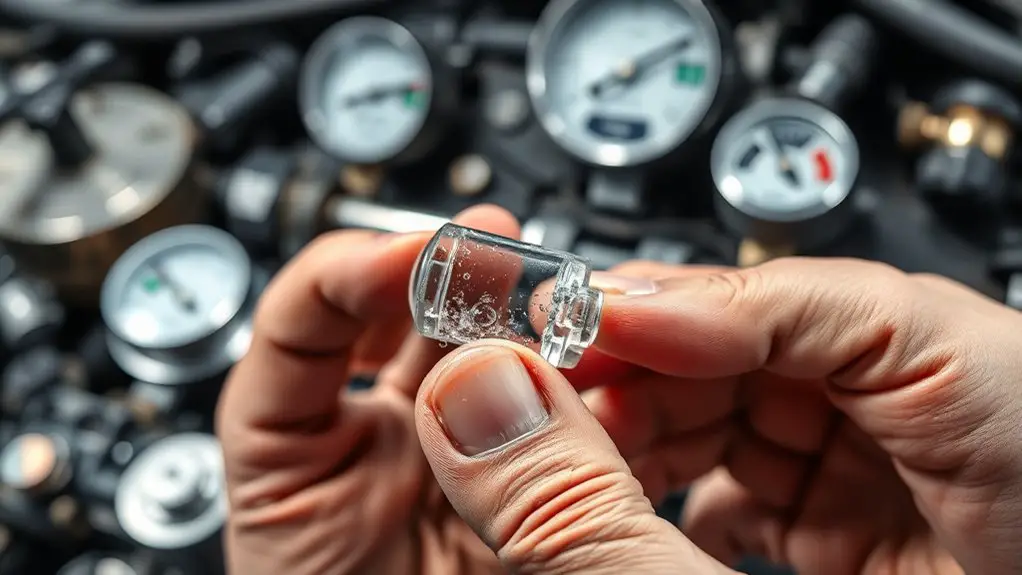
Checking for Air Bubbles in Transparent Sections

You’ll start by inspecting any transparent sections for visible bubble indicators, noting their size, location, and frequency. Next, perform clear-section checks to guarantee bubbles aren’t obscuring critical pathways or seals, and document findings for safety reviews. If you spot anomalies, pause, verify with a secondary method, and proceed only after confirming system integrity.
Visible Bubble Indicators
Visible bubble indicators are a straightforward way to confirm the presence and size of air pockets in transparent sections. You’ll inspect the surface for moving or stationary pockets, noting their positions and persistence. Observe bubble size by comparing each bubble’s diameter against a reference grid or ruler placed beside the view window. Track bubble formation dynamics as you watch: do bubbles form rapidly, gradually, or sporadically? Document timings and any changes after gentle orientation adjustments, since flow or tilt can influence visibility. Maintain steady lighting to minimize glare and guarantee accurate detection. Prioritize safety: avoid disturbing seals or coatings, and disconnect power when accessing live systems. This method supports cautious, freedom-driven examination without overstepping safety bounds.
Clear Section Checks
Clear Section Checks are your second line of sight for air pockets in transparent sections. You scan each pane or window with calm, deliberate focus, noting any visible distortions or shifting reflections. Move slowly, observing both edges and center, and compare with baseline images you’ve saved. If a bubble appears, pause to verify its position before taking action. Prioritize secure seals, proper orientation, and clean surfaces to prevent misreads. Maintain consistent lighting to avoid glare that hides pockets. Regularly perform clear section maintenance, documenting dates, findings, and remedies. Apply steady pressure only where needed, never pry forcefully. This discipline reduces risk and supports air pocket prevention. You gain reliability, safety, and the freedom to inspect on your terms.
Identifying Sluggish Startup and Repeated Re-priming
When a tool or appliance shows a sluggish startup, it’s often the sign of air pockets interfering with the initial surge of fuel or air mixture. You’ll want a calm, methodical approach to identify and address it without risking safety. Begin by confirming fuel or air lines aren’t kinked, then perform controlled re-priming: use manufacturer steps, keep PPE handy, and avoid rushed operations. If repeated re-priming attempts fail, pause and reassess for persistent pockets, then repeat only with deliberate timing. Document any patterns to distinguish startup issues from transient quirks. Progress with measured pulses, not brute force, to minimize wear. Ascertain all connections are snug and clean before starting. If stability remains elusive, consult a manual or technician rather than forcing a hot, unsafe start. Startup issues often respond to patient, systematic re-priming methods and careful observation rather than quick fixes.
| Step | Checkpoint |
|---|---|
| 1 | Verify lines |
| 2 | Gentle priming |
| 3 | Secure connections |
| 4 | Test start |
| 5 | Log results |
Inspecting Fluid Levels and Sight Glass Clarity
Start by checking fluid levels and sight glass clarity to confirm accurate readings. You’ll verify that you’re in the recommended range with minimal disturbance to the system. Inspect the fluid surface for uniform color and absence of foam, which can indicate air pockets or contamination. If the sight glass shows milky or cloudy fluid, pause and purge air cautiously before proceeding. Use clean gloves and a designated flashlight to enhance visibility without introducing debris. Note the fluid maintenance schedule and compare current level against calendar-based or system-specific gauges. When levels look low, top up only with the specified fluid type and viscosity, then recheck after a brief cycle to confirm stability. Record readings, dates, and any deviations. Maintain a clean work area, avoid splashes on electrical components, and make sure caps and seals are fully tightened. This approach supports safety, accuracy, and reliable performance. sight glass awareness safeguards your system’s integrity.
Looking for Temperature Inconsistencies Across Zones
To identify temperature inconsistencies across zones, systematically compare readings from each sensor against the baseline or design specification for that area. You’ll perform a clear, linear audit: note each zone, record current temperatures, and mark deviations beyond acceptable tolerances. Keep the process focused on data, not guesswork, and document every step for traceability. Temperature mapping should reveal subtle gradients, while zone analysis highlights pockets that diverge due to airflow or insulation gaps. If a sensor reads consistently high or low, verify calibration, sensor placement, and potential interference from adjacent equipment. Eschew assumptions; confirm with repeated measurements at different times, especially after changes in load or lighting. Maintain safety by de-energizing equipment only when approved and following lockout-tagout procedures. Use concise notes and timestamps to support airflow improvements or corrective actions. This approach empowers you to detect anomalies quickly, preserving system reliability and the freedom to optimize performance.
Evaluating Pump and Valve Performance for Air-Related Delays
As you move from mapping temperatures to evaluating airflow effectiveness, evaluate how pumps and valves are influencing air delivery in each zone. You’ll assess pump calibration to confirm consistent flow rates, listening for unusual hums or accelerations that hint at strain. Next, review valve adjustments, ensuring each control aligns with its zone’s demand without producing turbulence or cold pockets. Document pressure readings and flow direction, noting any lag between change commands and response. If a zone lags, check for partial blockages, worn seals, or misaligned fittings that could delay air movement. Prioritize safety: power down procedures when inspecting components are required, and keep hands clear of moving parts during tests. Maintain a conservative approach—small, repeatable tests prevent overcorrection. Record outcomes, then compare against baseline curves to identify deviations. This disciplined check helps you preserve freedom to fine‑tune while avoiding unintended consequences.
Conducting Quick Bleed Checks and Prime Procedures
You’ll start with a quick bleed to release any trapped air, then verify the line is firm and free of leaks. Follow the prime procedures in a clean, controlled sequence, ensuring all connections are snug and the system is properly primed before re-pressurizing. Keep safety at the forefront by wearing appropriate PPE and documenting any deviations or observations for review.
Quick Bleed Checks
If you’re performing quick bleed checks, start by ensuring the system is safely depressurized and that all energy sources are isolated. You’ll locate the bleed valves or ports at high points and prepare a catch container. Use a calibrated hand valve to crack open slowly, listening for steady hiss with no spurts. Observe metal fittings for leaks as pressure drops to the prescribed level. Maintain a deliberate pace to prevent water hammer or air displacement. Record readings, noting any beading or persistent pockets after venting. Perform quick bleed techniques in short, controlled bursts, then recheck system pressure and integrity. This approach supports effective air removal while preserving safety, ensuring you regain full flow without introducing new variables.
Prime Procedures Summary
Combining quick bleed checks with prime procedures streamlines air removal and system readiness: you’ll depressurize safely, isolate energy sources, locate high-point bleed ports, and prepare a catch container before gently cracking the valve to initiate controlled venting. You’ll then execute prime techniques with deliberate steps, using proper prime tools, to guarantee steady air purge and repeatability.
1) Execute a controlled depressurization sequence, verify isolation, and identify the best high-point port.
2) Apply prime tools to bleed, monitor flow, and cap the vent once clear.
3) Document results, inspect seals, and reset for the next cycle to maintain readiness.
With these prime techniques, you preserve safety while maintaining freedom, precision, and system reliability.
Frequently Asked Questions
How Do Air Pockets Affect System Efficiency Long-Term?
Air pockets wilting your system’s rhythm drag down performance, reducing efficiency over the long haul. They impede flow, raise pressure differentials, and force pumps to work harder. If you neglect air removal, heat and wear creep in, shortening components’ life. You’ll waste energy and money. You’ll want steady circulation, steady temp. You’ll monitor, purge, and vent as needed. You’ll protect system performance by timely air removal and disciplined maintenance.
Can Air Pockets Cause Chemical Corrosion Over Time?
Yes, air pockets can promote chemical corrosion over time. You’ll see stagnation, uneven cooling, and localized chemical reactions at metal interfaces. To counter this, prioritize thorough flushing, proper venting, and consistent monitoring as part of your corrosion prevention plan. Maintain clean systems, control oxygen levels, and inspect fasteners regularly. If you notice pitting or discoloration, act quickly; safe handling and proactive maintenance are essential for preserving system integrity and performance.
Do Sound Changes Indicate Air Pockets in Non-Metal Pipes?
Yes, sound changes can indicate air pockets in non-metal pipes. You’ll likely notice sound anomalies like banging, tapping, or clunks during flow, and you should assess pipe vibrations for irregular intensity or resonance. Approach cautiously, shut off water before inspecting, and verify with a trusted professional if unsure. Document patterns, avoid drastic fixes, and prioritize safety. If fluctuations persist, call a plumber; inconsistent vibrations could signal air pockets needing proper venting or flushing.
Are There Warning Signs in System Telemetry Dashboards?
Yes—warning signs show up in system telemetry dashboards. Start with a striking stat: you’ll spot a 15–30% alert rate spike during anomalies, catching you early. Look for system alerts like pressure drops, rapid sensor drift, or unexpected valve states, and correlate them with telemetry indicators such as timestamped trends and cross-sensor diffs. You should act methodically, prioritizing safety, documenting findings, and validating readings before proceeding to maintenance or isolation. Stay proactive, stay compliant.
What Safety Steps Prevent Air-Related Hydraulic Shocks?
Yes. To prevent air-related hydraulic shocks, you should implement proper pressure relief procedures and routine system maintenance. Start by verifying all relief valves function correctly and set to the correct trip pressures. Regularly purge air from lines, monitor pressure fluctuations, and inspect fittings for leaks or looseness. Maintain clean reservoirs, replace filters as scheduled, and document every check. You’ll gain smoother operation, fewer transients, and safer performance while preserving system integrity and your peace of mind.