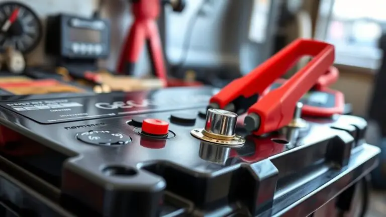
Step-By-Step: Fixing a Faulty Connector Pins That Triggers Wheel Speed Sensor Fault
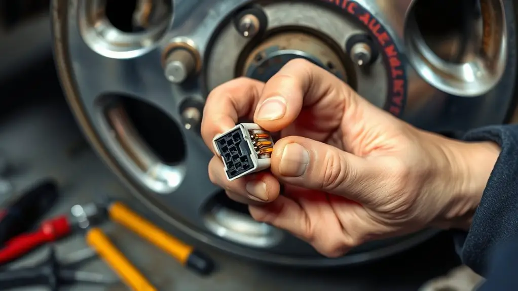
To fix a faulty connector pin that triggers a wheel speed sensor fault, start by isolating the hub area and inspecting the harness for damage and sharp bends. Clean corrosion with isopropyl alcohol, then reseat the connector, aligning keying features. Test resistance and continuity across each pin pair, and locate the faulty segment. Replace damaged pins or the entire connector as needed. Reassemble, recheck sensor signals, and document results; you’ll uncover more steps if you keep exploring.
Diagnosing the Wheel Speed Sensor Fault Origin
To diagnose the wheel speed sensor fault origin, start by confirming which sensor(s) are implicated using fault codes or a scan tool. You’ll isolate signals from each wheel and compare live data to expected vehicle math. If codes point to a particular sensor, verify power, ground, and signal integrity at the harness connector. Inspect the sensor’s mounting, reluctor ring alignment, and any obvious mechanical interference. Document whether intermittent readings correlate with speed, load, or suspension movement. When you assess sensor malfunction causes, differentiate electrical faults from mechanical misalignment. Check harness continuity and sensor insulation for damage, kinks, or pin corrosion that could produce false trips. Consider environmental factors like moisture or oil that can degrade readings. Regarding wiring insulation types, note that flexible, thermally stable insulation tends to resist cracking under temp cycling, while rigid varieties may crack and expose conductors. Conclude with a reversible tests plan to confirm the fault origin before replacement.
Tools and Safety Precautions for Electrical Inspections
You must wear appropriate PPE and follow PPE best practices before starting any electrical inspections. Use the correct electrical inspection tools, maintain tool integrity, and keep safety protocols consistent throughout the process. This section introduces the essential PPE and tool-use guidelines that protect you during wheel speed sensor fault investigations.
PPE and PPE Best Practices
PPE and proper PPE best practices are essential in electrical inspections to protect against shock, arc flash, and thermal hazards. You approach each inspection with a defined plan, selecting appropriate personal protective equipment and safety gear before you touch any conductor. Verify ratings, inspect for damage, and don’t improvise—you confirm the PPE integrity and fit. You wear insulated gloves, arc-rated clothing, eye protection, and a face shield when exposed to potential arc events. You maintain a clean, dry work area, test fault paths with approved equipment, and de-energize circuits whenever possible. Documentation is concise: log PPE checks, condition, and replacements. Your discipline minimizes risk, enhances precision, and preserves workflow. You respect safety gear standards, stay current, and proceed deliberately.
Electrical Inspection Tools Use
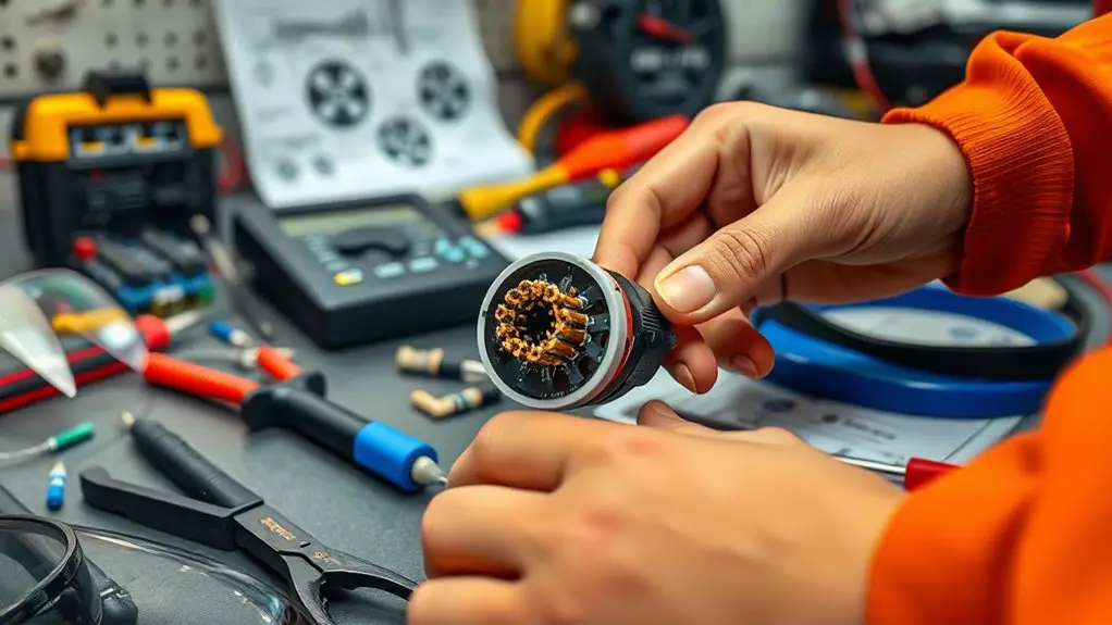
In electrical inspections, the right tools and their safe use define accuracy and worker protection. You’ll select insulated probes, a digital multimeter, and a non-contact voltage tester for baseline assessments. Keep calibration current and verify test leads are intact before touching any circuit. Establish a systematic workflow: first, isolate power, then ground yourself, and use labeled test points to minimize error. Your electrical troubleshooting techniques rely on consistent technique: measure resistance, continuity, and voltage with intent, noting polarity and reference points. For voltage measurement methods, prefer low-energy probing when possible, and document readings with time stamps. Always follow equipment manuals, use PPE as needed, and maintain organized, traceable records. Precision in tool use safeguards outcomes and supports confident fault isolation.
Locating the Faulty Connector in the Wheel Assembly
To locate the faulty connector in the wheel assembly, start by isolating the wheel hub area and inspecting the harness routing for obvious damage or pinched wiring. You’ll trace the harness from the sensor to the vehicle connector, noting any sharp bends, heat exposure, or crushed sections that suggest mechanical wear. Maintain clean work space and document accessibility; guarantee you can retract the loom without stressing pins. Check for loose or misaligned connectors at both ends, confirming a firm, audible seat when mated. Look for signs of moisture ingress, insulation wear, or exposed conductors near the wheel bearing housing. Record any abnormal gaps or mismatches in loom spacing that could create intermittent contact. This is about faulty connections and connector identification: verify each adjacent pin aligns with its mate and appears free of corrosion or deformation. Conclude by isolating the suspect bundle for targeted testing in the next step.
Inspecting Pins for Corrosion or Wear
You should inspect the pins for corrosion indicators, noting any greenish or blue residue and white oxidation around the contact faces. Check wear patterns on the mating surfaces and edges, looking for thinning, pitting, or scalloped grooves that could disrupt signal transfer. Keep the connector clean and free of debris, observing cleanliness cues like lint-free contacts and secure, snug seating to guarantee reliable contact.
Pin Corrosion Indicators
Pin corrosion indicators are a critical check in wheel speed sensor diagnostics; inspecting the pins for corrosion or wear helps determine if electrical connection integrity is compromised. You’ll inspect connector pins with good lighting, looking for greenish, whitish, or black residues, dullness, or etched paths. Test for looseness by gentle wiggling, and feel for any roughness or lift at the tip. Measure continuity if you have a multimeter, noting elevated resistance or intermittent readings. Document any corrosion spots and track their progression over time. Prioritize pin maintenance routines that remove oxidation safely and reseal terminals to minimize moisture ingress. Implement corrosion prevention practices: clean, dry contacts, dielectric grease where appropriate, and secure seals. Maintain a proactive schedule to sustain reliable sensor signaling and system performance.
Wear Patterns Checked
Wear patterns on connector pins reveal wear or deformation that can compromise signal reliability. You’ll inspect each pin for uneven wear, burrs, or thinning that hints at contact fatigue. Compare edges, test faces, and mating surfaces for symmetry; note any discoloration that signals oxidation. If wear patterns appear prominent, document location and severity, then plan a corrective approach to preserve connector stability and signal integrity. Use a magnifier to verify subtle changes, and rotate or replace pins only when required by measured tolerance swings. Maintain a clean, controlled environment and handle parts with precision.
| Pin | Observed wear | Action |
|---|---|---|
| 1 | mild edge wear | monitor |
| 2 | no wear | nominal |
| 3 | slight burr | file cautiously |
| 4 | discoloration | replace |
| 5 | edge thinning | assess replacement |
Connector Cleanliness Cues
Connector cleanliness cues build on observed wear patterns by focusing on signs of corrosion, contamination, and residue on pins. You inspect each contact surface with steady, deliberate motion, noting dulling, pitting, or discoloration that reflects electrical stress. Look for green or white verdigris, waxy films, or metallic flecks that indicate oxidation or debris intrusion. Check pin alignment and spring tension; bent or loose pins create micro-arcs and gaps. Cleanliness means more than absence of grime: it’s confirming no conductive residue remains after inspection. Use a lint-free cloth, isopropyl alcohol, and a gentle brush to remove surface contaminants, then re-evaluate contact integrity. Document findings for connector maintenance records, ensuring electrical hygiene is preserved for reliable wheel speed sensor communication and system freedom from intermittent faults.
Cleaning and Treating Corroded Connectors
Clean and careful cleaning starts with identifying corroded terminals and harness pins. You’ll inspect each contact for greenish or whitish buildup, and note any discoloration that signals electrolyte leakage or moisture intrusion. Proceed with a controlled disassembly to access the connector housing, keeping components organized. Use a non-metallic pick to free debris without scraping the mating surfaces, then apply isopropyl alcohol to dissolve salts and swab away residue. For stubborn corrosion, substitute a dedicated contact cleaner or a citrus-based degreaser, ensuring you follow the product’s safety instructions. After cleaning, dry thoroughly with compressed air at low pressure, and recheck for any remaining oxidation. Apply a light coat of electrical contact protectant or corrosion inhibitor to all pin surfaces, avoiding over-application that could attract dust. This approach supports connector maintenance and corrosion prevention while preserving signal integrity and sensor reliability, enabling a confident reassembly and continued performance without introducing new faults. Remember: precision preserves freedom.
Reconnecting and Seating the Connector Properly
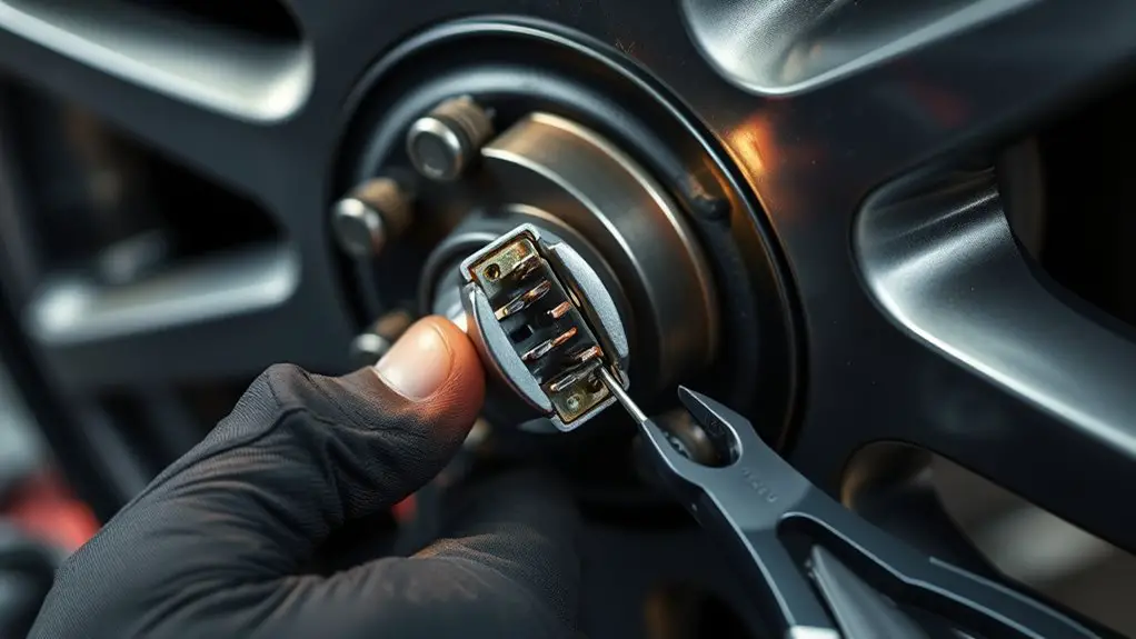
Once you’ve verified the pins are clean and dry, reinsert the connector straight into the receptacle, aligning the keying features first to prevent misalignment. You’ll feel a definite seating resistance as the connector seats; proceed with steady, even pressure until you hear or feel a secure latch engage. Inspect the housing for any gaps that could indicate skewed alignment, and confirm the mold marks align with the mate. Use deliberate, perpendicular pressure rather than angling the plug, which preserves pin integrity and prevents side loading. Consider connector types you’re dealing with, noting that some designs require a quarter-turn or a mid-seat reset before final engagement. Apply a light, even tug after seating to verify retention without stressing wires. For seating techniques, make certain the harness grommet remains undisturbed and route the wiring as originally positioned to minimize movement under operation. Record the exact seating outcome for future diagnostics.
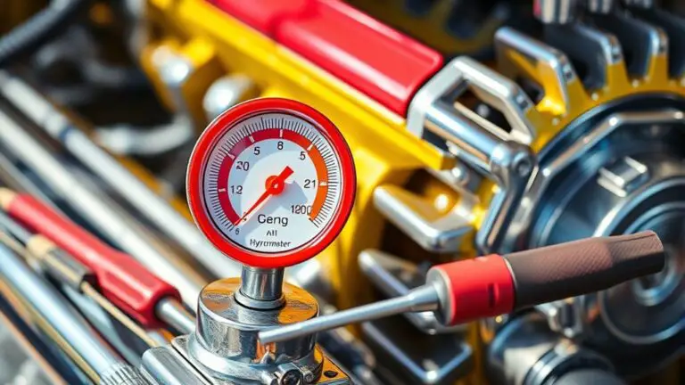
Testing Resistance and Continuity in the Wiring
After confirming the connector seating, you’re ready to evaluate the electrical path by testing resistance and continuity. You’ll follow a disciplined approach to verify signal integrity without guessing. Begin with the wheel speed sensor circuit reference and ground, then compare readings to expected values from wiring diagrams. Use a multimeter to measure resistance across each pin pair, noting whether values align with resistor values in the schematic. Next, check continuity along the harness to confirm unbroken copper and proper routing. If you encounter open or shorted paths, recheck connectors and suspected joints before proceeding.
- Inspect resistance values against wiring diagrams and specify acceptable tolerance ranges
- Trace each conductor for continuity, ensuring no breaks or unintended shorts exist
- Document readings methodically, labeling each pin and corresponding path for traceability
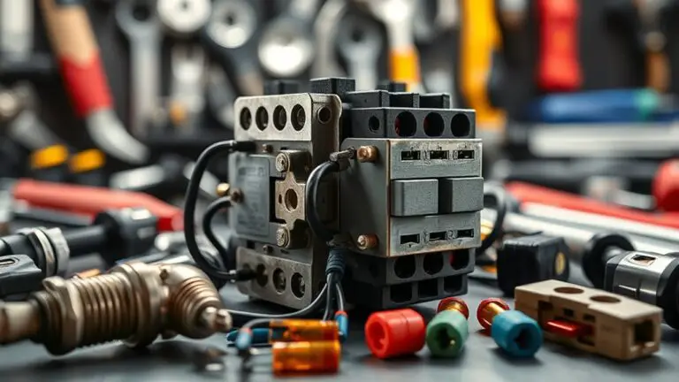
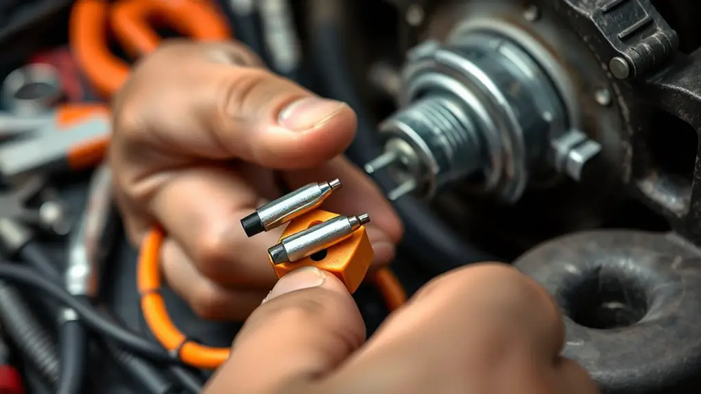
Replacing Damaged Pins or Connectors
Damaged pins or connectors must be replaced to restore a reliable sensor circuit. You begin by isolating the faulty segment, identifying either bent pins, corroded contacts, or cracked housings. Gather replacement parts that match the original specifications, ensuring compatible pin count and signal integrity. Use a precise toolset: micro-nippliers for pins, a fine pick for clearing debris, and a calibrated crimping tool for secure terminations. Inspect the mating connector housing for cracks or deformation; replace the entire connector if structural integrity is compromised. When swapping, preserve conductor orientation and keep wiring orderly to avoid cross-talk or pin misalignment. Perform a controlled replacement sequence: disconnect power, note wire colors, detach the damaged assembly, and install the new connector or individual pins with proper crimp or solder joints. Test continuity after each step, and confirm the harness is seated fully. This reduces future failures, supports durable connector replacements, and mitigates risk from damaged components before reassembly.
Reassembling the Wheel Area and Rechecking Systems
Reassemble the wheel area with all connectors snug and seated, then verify that each system connection is secure. Recheck sensor wiring and harnesses for proper routing and absence of strain or pinched paths. After reassembly, verify sensor signals to confirm correct communication and fault-free operation.
Reassemble Wheel Area
As you begin reassembling the wheel area, start by confirming that all components—hub, studs, rotors, and sensors—are clean, undamaged, and properly aligned, then securely torque fasteners to the manufacturer’s specifications.
- Verify wheel assembly alignment and seating to prevent rotor binding
- Inspect connector maintenance paths for clear routing and debris-free pins
- Recheck fastener torque with a calibrated torque wrench before test spin
You proceed with calm, deliberate motions, ensuring the brake dust shield sits correctly and the rotor surfaces remain pristine. Fit the caliper, then reconnect any wiring harnesses routed near the suspension. Spin the hub gently to feel for smooth rotation, listen for binding, and confirm no unusual clearance. Finally, perform a cautious road test to validate absence of abnormal noise or drift.
Recheck System Connections
Before proceeding, guarantee every connection in the wheel area is intact and properly seated; double-check that harnesses, sensors, and ground straps are free of damage, securely attached, and routed away from moving parts. You’ll reassess all connectors for signs of corrosion, pin alignment, and seating depth, then reseal as needed to maintain wiring integrity. Reassemble components with deliberate torque and confirmed clearances, avoiding pin shift during mounting. Inspect the harness routing for tight bends, exposed conductors, and potential chafing, correcting paths to reduce stress. Perform connector maintenance by reseating each connector until you hear a definitive click and verify retention. Finally, test continuity across critical circuits, confirm absence of voltage drop, and document results to preserve wiring integrity and reliable sensor communication.
Verify Sensor Signals
To verify sensor signals after reassembly, systematically power up the wheel-area system and confirm all wheel speed sensor outputs are within specification.
- Verify sensor calibration by comparing each output against the manufacturer’s baseline, noting any deviation.
- Assess signal stability across repeated spins and steady-state runs to detect intermittent faults.
- Document anomalies, then recheck wiring continuity and connector seating to guarantee consistent readings.
Proceed with a controlled test: monitor real-time sensor data, log values, and confirm symmetry between left and right wheels. If a channel shows drift or jitter, halt, inspect shielding, re-seat pins, and recheck ground paths. Maintain concise records for diagnostic tracing. The goal is robust sensor calibration and stable signals, enabling reliable wheel speed data and system confidence.
Preventive Tips to Avoid Future Connector Issues
Regular inspection and proactive maintenance are essential to prevent future connector issues. You’ll keep performance predictable by establishing a routine that targets contact surfaces, seals, and routing. Begin with preventive maintenance: schedule sensor and connector checks at defined intervals, clean or replace corroded terminals, and verify lockpins engage fully. Inspect wiring harness routing for tight bends, pinch points, or abrasion; correct concerns before they become faults. Use connector protection practices: apply dielectric grease sparingly to reduce moisture ingress, reseal weatherproof enclosures, and replace degraded seals to maintain enclosure integrity. When reassembling, confirm alignment pins seat without forcing parts, and torque fasteners to spec to preserve clamping force. Document observations and actions for traceability, so trends surface early. Store spare connectors and seals in a clean, dry kit, labeled for quick deployment. You’ll improve reliability, minimize downtime, and sustain accurate wheel speed sensing through disciplined preventive maintenance and connector protection.
Frequently Asked Questions
Can a Faulty Connector Cause Intermittent Wheel Speed Sensor Readings?
Yes, a faulty connector can cause intermittent wheel speed sensor readings. You’ll want to inspect the connector alignment, clean corrosion, and reseat it firmly. Check for damaged pins and replace if needed. Perform connector maintenance with a multimeter to verify continuity and resistance against specs. Keep vibrations in mind, secure the harness, and recheck readings after every reassembly. This methodical approach preserves sensor fidelity and guarantees reliable sensor readings, while maintaining vehicle freedom and performance.
Do Aftermarket Connectors Affect Sensor Accuracy or Vehicle Safety?
Around 60% of wheel speed sensor failures traced to connector issues, so aftermarket connectors can degrade sensor reliability. Do they affect sensor accuracy or vehicle safety? Yes, if you choose low-quality parts, reliability drops and misreads can occur, compromising safety. Focus on aftermarket quality to preserve sensor reliability. You’ll want precision-spec terminals, correct gauge wiring, and robust seals. If in doubt, verify with OEM-equivalent specs and test continuity, insulation, and signal integrity before road use.
How Often Should Wheel Sensor Connectors Be Inspected During Maintenance?
You should inspect wheel sensor connectors during maintenance at least every 6 months, or more often if you drive in harsh conditions. During each inspection, perform a thorough connector inspection for corrosion, loose pins, and damaged seals, and verify pin alignment. If you spot wear, clean and reseat connections, then recheck with diagnostic tools. Adopting this disciplined sensor maintenance routine helps maintain reliability and safety without sacrificing your freedom to enjoy your drive.
Can a Wiring Harness Harness Routing Cause Connector Stress or Leaks?
Sure—yes, a wiring harness routing can cause connector stress or leaks. You’ll want to trace paths away from sharp edges, heat sources, and moving parts, and secure harnesses to minimize vibration. Check for pin misalignment and seal integrity, replacing compromised connectors. Monitor for wiring stress and signs of connector leaks, then re-route or shield as needed. You maintain reliability by documenting changes, testing continuity, and ensuring proper exposure to environmental protections.
Are There Engine Codes That Indicate Only Connector Faults?
Some engine codes can point to connector faults, but they rarely accuse only connectors. You should perform connector diagnostics alongside wiring checks. Look for pin corrosion and high-resistance paths, not just sensor codes. Use a scan tool to tease out multi-system codes and confirm with continuity tests. If codes implicate the wheel-speed circuit, inspect connector pins and seals for corrosion, looseness, or contamination. You’ll improve reliability by addressing pin corrosion early.