How Temperature Affects Ground Strap and Causes Battery Age-Related Failure
Temperature swings raise ground-strap impedance, increasing resistance at contacts and fostering micro-arcing during faults or transients. As heat climbs, metal resistivity shifts and differential expansion loosens clamps, which degrades reliability and accelerates aging through creep and fatigue. Cold stresses raise brittleness, elevating contact resistance and slowing charge paths. Over time, corrosion and microcracks emerge, widening impedance variance across cycles. Diagnostics—impedance trends, thermal imaging, and clamped-contact checks—help quantify risk, guiding design choices; more details await.
The Role of Ground Straps in Battery Packs
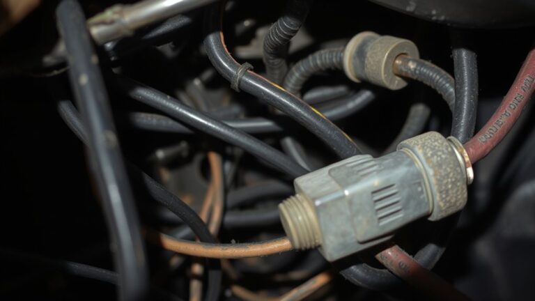
Ground straps serve as low-impedance pathways that divvy electrical faults and transient currents away from sensitive battery cells, maintaining a uniform potential across the pack. In this section, you’ll assess how the role of ground straps shapes pack reliability. You observe that a robust electrical connection minimizes impedance variation between cells and chassis, reducing localized heating and potential micro-arcing under fault events. You quantify strap cross-section, length, and material, linking these to impedance and transient response. You test different connection schemes, noting how secure clamping and clean contact surfaces sustain low resistance over cycles. Ground strap maintenance emerges as a data-driven discipline: small corrosion pockets or loosening fasteners can measurably raise impedance and shift pack dynamics. You document failure modes, including intermittent grounding and strap fatigue, correlating them with thermal cycling. The goal is a repeatable maintenance protocol that preserves electrical connectivity, guarantees uniform potential, and supports long-term apparatus freedom in design and operation.
How Temperature Shifts Affect Electrical Resistance

You’ll examine how temperature shifts alter electrical resistance, focusing on the relationship between temperature and resistance across common conductors. Data-driven trends show resistance increases with temperature in metals and can vary with material, cross-section, and impurity content, influencing circuit behavior. Expect clear quantifications of temperature coefficients, observed shifts in conductivity, and implications for ground straps and battery packs under varying thermal loads.
Temperature and Resistance
Temperature influences resistance through the intrinsic properties of conductive materials: as temperature rises, atomic vibrations increase, scattering electron paths, and the net resistance typically increases in metals but can decrease in some semiconductors. You’ll examine how these shifts translate to measurable resistance changes under controlled conditions. Data-driven observations show a positive temperature coefficient for most metals, with linear approximations holding over practical ranges and nonlinear deviations near phase changes. In semiconductors, temperature effects can reduce resistance as carrier concentration grows, yet mobility declines, yielding complex, material-specific curves. You’ll quantify these trends using precision instrumentation, documenting repeatable, threshold-based responses. For ground straps and battery interfaces, expect nuanced resistance changes tied to contact metallurgy, microstructure, and thermal gradients, guiding design choices that balance reliability, safety, and performance.
Thermal Impact on Conductivity
Thermal shifts alter a conductor’s resistance by modulating carrier dynamics and lattice scattering: as temperature rises, most metals exhibit increased resistance due to enhanced phonon activity, while certain materials—especially some semiconductors—may show reduced resistance as carrier concentration rises, albeit with mobility constraints.
- Thermal conductivity variations align with lattice vibrations and impurity scattering, informing design margins
- Temperature extremes stress contact interfaces, altering effective cross-section and resistive pathways
- Carrier concentration and mobility tradeoffs define net conductivity under rapid thermal transients
- Material selection hinges on predictable, data-supported resistance versus temperature profiles
- Experimental measurements quantify reproducible shifts, enabling robust thermal management strategies
You’ll interpret results with precision, linking observed resistance trends to underlying physics while keeping the focus on practical implications for freedom-loving, data-driven design.
Shifts in Electrical Resistance
As temperature shifts occur, electrical resistance responds through changes in carrier dynamics and lattice interactions that can be quantified with precision. You observe how resistance changes correlate with phonon scattering, impurity interactions, and band structure adjustments that unfold across temperature ranges. In this framework, electrical conductivity tracks inverse resistance, revealing distinct regimes: metallic-like slopes at low temperatures give way to activated behaviors as thermal energy rises. You measure monotonic or nonlinear trends, noting activation energies and crossover points that signal dominant scattering mechanisms. Data-driven comparisons across materials and geometries highlight how contact resistance, grain boundaries, and substrate effects modulate overall behavior. By focusing on precise measurement, you gain actionable insight into reliability, performance margins, and design strategies for robust ground strap performance under temperature fluctuations.
Thermal Expansion and Contraction in Strap Materials

When strap materials experience temperature changes, their dimensions shift through expansion or contraction governed by the material’s coefficient of thermal expansion; this behavior directly affects clamp force, impedance to electrical contact, and overall strap integrity. You’ll observe predictable dimensional changes with thermal cycling, mapping stress states to performance. Data show how differential expansion between strap and terminal hardware alters contact area and contact resistance, driving transient impedance fluctuations. Material fatigue emerges after repeated cycles as microcracks propagate at interfaces, reducing stiffness and clamp reliability. Precision measurements reveal correlations between elongation, tensile stress, and junction warm-up. Design implications emphasize selecting materials with matched coefficients, controlled loop geometry, and robust termination interfaces to minimize stress concentrations. In practice, your testing should quantify dimensional drift, force retention, and impedance drift across temperature ramps. Emphasize repeatability, traceability, and uncompromised data logging to support life-cycle assessments.
- Thermal cycling impact on expansion
- Coefficient of thermal expansion matching
- Contact impedance and clamp integrity
- Dimensional drift under temperature ramps
- Early indicators of material fatigue
Creep, Fatigue, and Strap Longevity Under Heat
Heat exposure accelerates creep and amplifies fatigue mechanisms in ground straps, degrading cross-section integrity and connection reliability over time. You’ll assess time-temperature data to quantify strain-rate changes, fatigue life, and failure modes under representative thermal profiles. This discussion centers on empirical metrics for creep strain, cycle durability, and longevity predictions to guide design margins.
Heat-Induced Creep Effects
Creep under sustained heat accelerates deformation in ground straps and adjacent battery components, reducing load-bearing capacity and hastening fatigue. You’ll observe progressive elongation and microstructural change that shift the stiffness envelope and alter current paths. Experimental data show localized necking and grain-boundary sliding correlate with reduced, unpredictable resistance to transients, highlighting heat deformation as a critical reliability driver. Material integrity hinges on alloy selection, strain-rate sensitivity, and thermal shielding effectiveness under elevated ambient temps.
- Heat-induced creep rate correlations with temperature and stress
- Microstructure evolution linked to resistance drift
- Strain hardening versus recovery under cyclic heating
- Temperature gradient effects on strap junctions
- Predictive indicators for longevity and failure thresholds
Strap Fatigue Under Heat
Despite elevated temperatures accelerating both creep and fatigue processes, strap longevity under heat hinges on the interaction between time-at-temperature, cyclic load amplitude, and microstructural evolution. You track fatigue pathways by isolating load cycles, noting that microstructural features—grain boundaries, precipitates, and dislocation networks—reorganize under thermal cycling. Fatigue life shifts with the strap composition, where alloying elements modify crack initiation sites and propagation resistance. Experimental protocols quantify stepwise damage accumulation, correlating hysteresis, irreversible strain, and surface decohesion with temperature rise. Thermal resilience emerges from a balance between hardening and recovery mechanisms; higher strain amplitudes accelerate degradation, while refined microstructures slow it. You interpret data to identify thresholds for safe operation, guiding design towards enhanced strap composition and predictable thermal fatigue performance.
Brittleness and Sluggishness in Cold Conditions
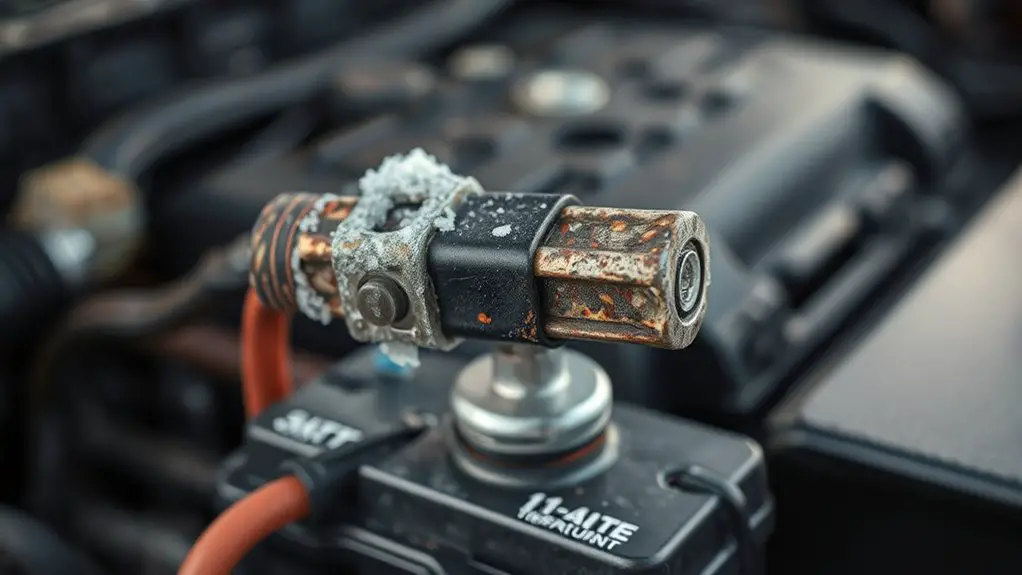
Cold conditions markedly increase material brittleness and frictional resistance in ground straps and battery components, leading to potential microcracking and sluggish electrical response. You will observe higher modulus effects, reduced ductility, and amplified contact resistance as temperatures drop, directly impacting current transients and response time. In cold weather, internal interfaces stiffen, causing microgaps to persist and slowing charge-discharge dynamics, which degrades battery performance over repeated cycles. You should quantify changes via controlled impedance measurements, corroborating with microstructure imaging to link brittleness to conduction pathways. Data-driven assessment highlights that small temp shifts yield disproportionate impedance growth, signaling early wear. Your approach blends mechanical insight with electrochemical testing to reveal cause-and-effect patterns in real-world operation.
- Material brittleness metrics across temperatures
- Frictional resistance and contact impedance shifts
- Microcrack initiation under cyclic load
- Transient response degradation during cold weather
- Correlation to battery performance metrics
Early Warning Signs of Strap-Related Aging
Early warning signs of strap-related aging emerge from subtle shifts in electrical and mechanical behavior that precede visible failure. You observe gradual increases in contact resistance and intermittent voltage drops under load, signaling evolving strap impedance. Small mechanical play or stiffness changes at mounting points accompany temperature-dependent creep, hinting at material fatigue before cracks form. Strap corrosion indicators appear as faint discoloration, micro-pitting, or electrolyte staining at joints, suggesting localized degradation that can accelerate aging under thermal cycling. In data terms, you’ll note rising impedance variance across cycles and a drift in temperature coefficients that diverges from baseline models. Aging detection methods rely on trend analysis of electrical measurements, thermal profiles, and mechanical torque consistency to flag accelerated wear early. You’ll prioritize oriented sampling during varied duty cycles to differentiate normal fluctuation from true aging. By correlating corrosion indicators with electrical drift, you establish a precursor map, improving maintenance scheduling and extending reliable operation under diverse temperature environments.
Diagnostic Techniques to Assess Strap Health
Diagnostic techniques to assess strap health rely on synchronized electrical, thermal, and mechanical measurements to quantify impedance evolution, corrosion indicators, and mounting integrity under controlled duty cycles. You perform targeted visual inspection and electrical testing to establish baseline—then monitor for deviations through time steps and temperature ramps. Data-driven interpretation highlights correlation between impedance shifts, thermal signatures, and mechanical loosening.
- visual inspection cues and corrosion streaks under varying temperatures
- electrical testing: impedance spectroscopy and contact resistance trends
- duty-cycle modulation to reveal hysteresis in mounting integrity
- thermal imaging to locate hotspots and solder joint reliability
- repeatability criteria and statistical confidence for aging trajectories
You document artifacts, normalize measurements, and compare to reference curves. You’ll flag anomalies that exceed thresholds, trigger controlled diagnostics, and prioritize preventive maintenance. The emphasis stays on measurable change, traceable data, and actionable decisions. You value freedom to pursue rigorous experiments, yet you keep conclusions concise and grounded in repeatable results.
Design and Material Choices to Mitigate Temperature Effects
Design and material choices to mitigate temperature effects focus on selecting thermally compatible substrates and components, then engineering interfaces to minimize thermal resistance and expansion mismatch. You assess material selection strategy by pairing low-CTE substrates with high-stability conductors, reducing interfacial stress under thermal cycling. Data-driven screening targets coefficient of thermal expansion, thermal conductivity, and moisture tolerance, filtering candidates before prototype builds. Design optimization proceeds through iterative calibration of bond lines, adhesive layers, and solder alloys to balance mechanical compliance with heat spread. You quantify thermal paths using finite-element models and infrared measurements, tracing temperature gradients from source to strap and battery interface. Material selection decisions are evaluated against reliability metrics, including drift under cyclic temperatures and time-to-failure distributions. You prioritize manufacturability and cost parity, ensuring scalable processes for consistent performance. The resulting design concentrates on minimizing thermal resistance and mismatch, enabling stable electrical performance across variable environments while maintaining freedom to innovate.
Practical Maintenance and Operational Guidelines
Regular maintenance hinges on proactive thermal monitoring and disciplined operational practices; you’ll establish cadence, collect measurements, and act on deviations before reliability degrades. You’ll implement standardized checks for ground strap temperature, ambient conditions, and insulation integrity, ensuring traceable records to strengthen preventive maintenance. Prioritize data-driven actions that preserve operational efficiency by correlating temperature trends with battery age indicators and load profiles. Maintain calibrated sensors, document alarm thresholds, and validate corrective steps through controlled tests. Emphasize conservative ramping of current during high-temperature events to minimize thermal shock and wear. Use root-cause analyses to distinguish environmental from systemic causes, updating procedures as findings accrue. Embrace ongoing optimization of maintenance windows to minimize downtime while maximizing reliability. Integrate condition-based triggers into maintenance planning, so preventive maintenance becomes routine rather than reactive.
- Establish sensor calibration schedule and documentation
- Define clear temperature thresholds and action workflows
- Log all deviations with context and outcomes
- Run controlled thermal stress tests
- Review KPI trends for continuous improvement
Frequently Asked Questions
How Do Humidity Levels Interact With Ground Strap Aging?
Humidity impact accelerates ground strap aging by promoting moisture-driven oxidation and subtle corrosion. You’ll see higher corrosion effects at elevated humidity, which can degrade conductivity and increase resistance, subtly altering charging profiles. Data show exponential wear with moisture exposure, particularly when combined with thermal cycling. You’ll observe that humidity interacts with insulating films and contaminants, magnifying degradation. Maintain controlled humidity to mitigate corrosion effects and stabilize long-term electrical performance.
Can Strap Materials Fail Differently Under DC Versus AC Operation?
Yes, strap materials can fail differently under DC operation versus AC operation. In DC, steady current favors uniform thermal buildup and electrochemical aging, while in AC, rapid switching induces localized heating, insulation fatigue, and microcrack propagation. You’ll observe greater dielectric stress and hysteresis losses under AC operation, accelerating wear. Data shows DC life aligns with steady current limits, whereas AC exposure requires higher protection margins, cooling, and materials with superior dielectric endurance to extend battery life.
Do Temperature Cycles Cause Micro-Cracking in Straps?
Temperature fluctuations can induce micro-cracking mechanisms in straps. Yes, repeated cycling stresses promote fatigue and crack initiation, especially at junctions and coatings. You’ll observe crack growth correlating with cycle count, humidity, and dwell time, yielding increased resistance. You should quantify using calibrated imaging and resistance telemetry, then model incubation and propagation under representative thermal profiles. Your data-driven approach will reveal thresholds where micro cracking accelerates aging, guiding material choices and design margins for freedom-loving experimentation.
What Is the Minimum Monitoring Frequency for Temperature-Related Strain?
Minimum monitoring frequency should be high enough to capture meaningful drift, typically once per hour in static tests and more frequently during cycles, but not so frequent as to overload data. You should implement continuous temperature monitoring paired with strain analysis, flagging anomalies within 5–10 minutes of onset. In practice, start with hourly data, then tighten to 15 minutes during transients, ensuring your dataset supports robust trend detection and reliable aging projections.
Are There Non-Destructive Tests That Predict Future Strap Brittleness?
Non-destructive testing can predict future strap brittleness by evaluating microstructural indicators and strain evolution. You’ll use techniques like ultrasonic testing, acoustic emission, and digital image correlation to track stiffness, porosity changes, and crack precursors. The data-driven approach enables you to forecast brittleness onset before failure, guiding preventive measures. Embrace experimental rigor, quantify thresholds, and document repeatability. You’ll balance sensitivity with practicality, ensuring rapid, actionable insights that support confident, freedom-minded decision-making.