
How Thermal Issues in Thermal Management Pump Cause Regenerative Braking Inconsistent and Fixes
Thermal issues in the pump core disrupt regenerative braking by shifting viscosity, pressure, and response timing, which makes braking torque less predictable and energy recovery uneven. When temperatures rise, pump efficiency drops and flow can drift, delaying pressure delivery and causing throttle errors. Proper thermal management—stable temperatures, minimized hotspots, and efficient cooling paths—keeps viscosity and pressure consistent. If temperatures stay controlled, braking remains steady; squeeze out the heat, and you’ll see the benefits unfold. You’ll learn more as you continue.
Understanding How Pump Temperature Affects Regenerative Braking Performance

Pump temperature directly impacts regenerative braking efficiency by influencing motor torque stability and electrical resistance. You’ll see how higher temperatures can cause motor windings to drift in torque output, reducing predictability during energy capture. In steady operation, pump efficiency ties into how evenly heat is distributed, preventing localized hot spots that skew torque and current response. Cold conditions improve frictionless movement, but overly cool pumps may introduce stiffness in seals, subtly altering flow paths that interact with regenerative pathways. Thermal dynamics describe how heat generation from electrical losses and mechanical load propagates through the fluid and housing, shaping pressure and impedance characteristics the controller relies on. You assess the system’s dynamic range by watching torque ripple and current spikes as temperature shifts. The goal is consistent energy recovery, achieved by maintaining stable temperature zones that preserve pump efficiency and predictable regenerative behavior. Freedom here means understanding limits, not ignoring them.
How Thermal Management Pumps Influence Energy Recovery and Braking Consistency
As you examine pump thermal load effects, you’ll evaluate how heat generation from the pump interacts with energy recovery dynamics and potential fluctuations in system demand. The discussion should link energy recovery stability to pump operating temperature, flow control, and duty cycles, highlighting how thermal inertia can modulate recovery efficiency. You’ll also identify braking consistency factors, such as pump response time, pressure regulation, and thermal-chemical effects on efficiency, to set a precise baseline for further analysis.
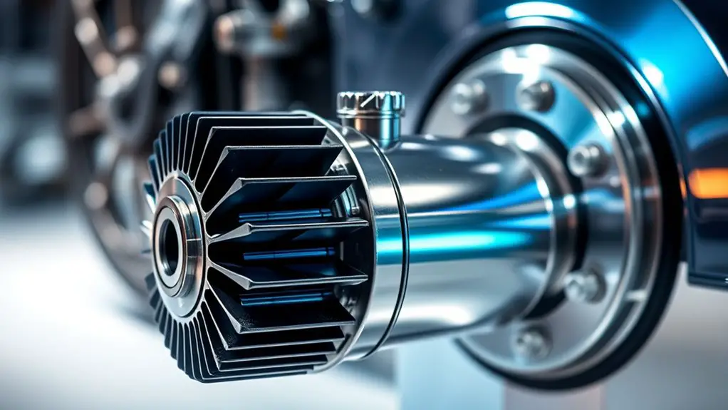
Pump Thermal Load Effects
Thermal load on the energy recovery and braking pump can subtly shift performance by altering hydraulic efficiency and response timing; when the pump overheats, viscosity changes and flow stability suffer, which in turn affects braking consistency and energy recovery accuracy. You’ll notice that elevated temperatures reduce pump efficiency, widening throttle error and delaying response to control signals. Heat also drives lubricant thinning or foaming, risking cavitation and noisy operation that degrades steady energy capture. Effective thermal insulation helps maintain stable viscosity, preserving predictable hydraulic behavior and enabling precise energy recovery metrics. Designing with modest thermal gradients minimizes transient losses during rapid braking cycles. In practice, you’ll optimize material choices and seal integrity to curb heat ingress and sustain consistent performance under load.
Energy Recovery Stability
Maintaining energy recovery stability hinges on how effectively the thermal management system preserves pump behavior under rapid braking and load variations. You’ll see that energy recovery depends on consistent pump performance, where temperature-driven viscosity changes and flow shifts impact system pressure and regenerative output. A stability analysis reveals how response time, thermal lag, and coolant properties shape recovery predictability, guiding design tolerances and control strategies. By aligning cooling metrics with pump duty cycles, you minimize fluctuations in recovered energy and braking feel.
| Factor | Impact on energy recovery |
|---|---|
| Thermal lag | Delays in temperature equilibrium affect recovery steadiness |
| Coolant properties | Viscosity and heat capacity control pump efficiency |
Braking Consistency Factors
Could small thermal shifts in the cooling loop quietly alter brake consistency? Yes, because even minor temperature variations within the pump circuit create uneven cooling. You’ll see how braking force responds to these gradients: when the pump’s cooling efficacy lags behind heat buildup, brake pressure sensing can drift, altering the regenerative contribution. Temperature gradients across the brake subsystem drive uneven heat removal, causing spatial differences in friction and energy recovery. You’ll observe that stable braking requires synchronized thermal states along the loop, ensuring uniform fluid temperatures at the actuator and caliper. By quantifying gradient magnitudes and correlating them with braking force variance, you identify that tight control of pump duty, flow, and cooling feedback minimizes inconsistency. In short, balanced thermal management supports repeatable regenerative braking.
Common Powertrain Architectures and Their Thermal Interdependencies

Common powertrain architectures—ranging from internal combustion engine, hybrid, to full electric configurations—impose distinct thermal loads and interdependencies across subsystems. You’ll assess how each topology channels heat through the engine, inverter, transmission, and cooling circuits, shaping overall thermal behavior. In an IC engine setup, fuel combustion dominates heat generation, producing thermal feedback that propagates to oil, headers, and the exhaust system, while cooling loops contend with transient torque demands. Hybrids blend thermal paths, balancing engine heat with electric machine cooling, battery thermal management, and circuitry losses, creating coupled heat transfer challenges. Full electric powertrains shift emphasis to battery and inverter temperatures, where parasitic losses and fast charging alter heat patterns, influencing performance stability. Across all architectures, you’re evaluating powertrain interactions—how cooling capacity, fluid temperatures, and heat rejection timelines interact with control strategies. The goal: predictable thermal responses that preserve regenerative braking effectiveness and system longevity, without sacrificing freedom in design and operation.
Indicators That Pump Heat Is Impacting Braking Control Systems
When pump heat begins to influence braking control, you’ll notice a change in system response measurable as delayed pedal feel, altered modulator timing, and greater variability in brake-by-wire or ABS actuation under high-load or extended-stop conditions. You’ll also see small, repeatable deviations in pedal position versus commanded braking, and occasional transient alarms or fault codes tied to sensor fusion or valve position estimates. In practice, indicators appear as subtle loss of linearity between pedal input and braking torque, especially during rapid changes or sustained braking at high ambient temps. You may observe inconsistent modulation under regenerative braking cycles, with brief mismatches between motor control and hydraulic brake outputs. These symptoms correlate to reduced pump efficiency and rising hydraulic temperature, amplifying heat dissipation demands. Recognize that such patterns don’t always point to a single failing component; they reflect system-level thermal sensitivity requiring targeted diagnostics and a holistic view of pump performance.
Cooling Design Strategies to Stabilize Pump Temperatures
As pump heat begins to affect braking control, it’s clear that stabilizing temperatures requires purposeful cooling design. You’ll want a focused approach that targets both steady-state and transient loads, balancing effectiveness with practicality. In practice, pump cooling should minimize thermal lag and prevent insulation gaps from creating hot spots, while keeping energy use in check. Thermal insulation must prevent external heat ingress without sealing off necessary airflow paths, preserving predictable response times. You’ll implement strategies that harmonize cooling capacity with enclosure geometry, fluid properties, and duty cycles.
- Use targeted convection paths and fins to maximize heat removal without adding mass or complexity
- Integrate low-flow bypass options to avoid pump overheating during startup or stall
- Couple insulation layers with vents or dampers to maintain stable gradients
- Validate with rapid thermal cycling tests to ascertain consistent output under real-world variations
These steps promote reliable, freedom-minded operation by reducing temperature swings and preserving control fidelity.
Thermal Pathways and Material Choices to Enhance Heat Transfer
Thermal pathways must be designed to direct heat efficiently from the pump core to the cooling medium, using a combination of high-conductivity materials and geometries that minimize resistance and lag. You’ll evaluate interfaces, contact pressure, and surface finishes to reduce thermal resistance. Prioritize continuous, anisotropic or isotropic materials with superior thermal conductivity, selecting metals for bulk transfer and composites for targeted routing where weight matters. Align pathways with flow channels to maximize convective exchange and limit stagnant pockets. Incorporate fins, microchannels, or folded geometries that expand surface area without adding excessive path length. For material choices, balance thermal conductivity with durability, corrosion resistance, and manufacturability, ensuring compatibility with lubricants and coolants. Apply heat dissipation techniques such as passive conduction, forced convection, and, where appropriate, phase-change enhancements to sustain uniform temperatures. Your design should enable predictable thermal behavior, supporting stable pump performance and regenerative braking consistency.
Control Strategies: Adapting Braking and Pump Operation to Heat Conditions
You’ll explore how heat conditions shape braking and pump control, focusing on heat-aware braking, pump operation adaptation, and temperature-driven regeneration tuning. This discussion asks how to balance braking deceleration with pump load to prevent overheating while maintaining performance. You’ll assess how sensor feedback and control logic translate temperature data into actionable adjustments for both braking and pump regimes.
Heat-Aware Braking Control
Heat-aware braking control integrates thermal data into braking and pump scheduling, enabling the system to reduce brake wear and prevent pump overheating by adjusting braking force and hydraulic flow based on real-time temperature readings. You assess heat patterns with thermal sensors and translate them into decisions that balance performance with durability. The approach emphasizes proactive cooling, not reactionary fixes, so you maintain alignment between braking demand and heat dissipation capacity. By coordinating brake modulation and pump pace, you reduce thermal spikes and extend component life without sacrificing control authority. This strategy supports freedom in design choices while preserving safety margins and system stability.
- Align brake force with heat trends from thermal sensors
- Prioritize gentle deceleration during high-temperature windows
- Modulate pump speed to match braking demand
- Validate outcomes through hotspot-aware testing
Pump Operation Adaptation
As thermal conditions shift, pump operation must adapt in tandem with braking demands to prevent overheating while preserving control authority. You calibrate the pump duty cycle to match thermal feedback, smoothing changes between regen and braking. By prioritizing pump efficiency under high heat, you avert performance sag and maintain steering feel. In practice, you implement load-sensing, modulating pump flow as temperatures rise, then releasing when cooling occurs to sustain consistency. Analytical monitoring reveals how slight timing adjustments improve stability without sacrificing response. Table imagery below aids intuition: a compact visualization of three factors—temperature, pump speed, and braking demand—across five scenarios, illustrating stable, changing, and stressed states. This approach embraces freedom through predictable, data-driven control.
| Temp | Speed | Demand |
|---|---|---|
| Low | Moderate | High |
| Med | High | Med |
| High | Low | High |
| Med | Low | Low |
| Low | High | Med |
Temperature-Driven Regeneration Tuning
Temperature-driven regeneration tuning focuses on aligning braking and pump behavior with real-time heat profiles to sustain control authority and efficiency. You adjust strategies based on current temperature maps, targeting stable regeneration despite thermal shifts. This approach emphasizes temperature optimization to minimize drift between expected and actual braking response, while preserving system integrity. You’ll perform regeneration calibration that tunes pump duty cycles and brake stiffness to local heat, avoiding overcooling or overheating. Precision comes from continuous sensing, rapid recalibration, and minimal latency. The goal is predictable braking feel, even as temperatures fluctuate. Implement flexible thresholds, validate with real-world ramps, and document outcomes for ongoing refinement.
- Real-time heat profiling informs braking and pump alignment
- Dynamic thresholding preserves control across temps
- Calibrated pump duty cycles reduce thermal lag
- Continuous feedback improves regeneration consistency
Sizing and Component Selection to Minimize Thermal-Induced Variability
Sizing and component selection should focus on reducing how thermal variance affects pump performance, because smaller, well-matched parts respond more consistently to temperature changes. You’ll prioritize tight tolerances, material compatibility, and compact packaging to minimize thermal lag and hot spots, boosting predictability in regenerative braking.
| Parameter | Impact on variability |
|---|---|
| Pump sizing | Sets thermal mass; smaller units heat and cool faster, reducing lag |
| Component durability | Withstands thermal cycling, preserving calibration over life |
This approach targets predictable dynamic response, where thermal-induced shifts stay within design envelopes. You weigh thermal conductance paths, guarantee low coefficient of thermal expansion, and prefer alloys with minimal drift. By selecting modules that heat and cool in concert, you reduce cross-coupling errors and extend service intervals. You’ll also document operational envelopes, confirming that size and durability choices do not compromise overall efficiency. The goal is disciplined, quantified decisions that maintain consistent pump behavior across a range of temperatures, preserving reliable regenerative braking while supporting freedom from unnecessary maintenance or recalibration.
Practical Implementation Steps for Reliable Regenerative Braking Under Heat Stress
To guarantee reliable regenerative braking under heat stress, implement a structured, stepwise approach that links thermal data to control actions and maintenance planning. You’ll map real-time temperature, pump load, and duty cycle to adaptive braking profiles, then validate with offline stress tests. Monitor thermal fatigue indicators and adjust control gains before performance degrades. Prioritize robust pump insulation to reduce transient spikes and extend sensor life, and schedule insulation health checks as a normal maintenance cadence. Integrate fault-logging that differentiates heat-induced braking variance from mechanical faults, and establish conservative thresholds for safe operation.
- Establish a real-time thermal model that informs braking torque decisions and guards against thermal fatigue onset.
- Profile insulation performance across ambient conditions and aging, updating maintenance intervals accordingly.
- Use adaptive control limits tied to verified load and temperature envelopes to prevent regime shifts.
- Document, review, and continuously improve the linkage between thermal data, control actions, and maintenance planning.
Frequently Asked Questions
How Quickly Does Pump Temperature Rebound After Peak Load Events?
Your pump temperature rebounds quickly after peak load, often within minutes, then settles toward a steady baseline. The rebound rate hinges on cooling efficiency, ambient temperature, and thermal mass. You’ll see faster recovery when you optimize pump cooling and minimize heat soak. Maintain good thermal insulation to reduce transient gains, and guarantee steady heat removal during duty cycles. In practice, monitor temps, verify insulation integrity, and tune cooling cycles for consistent, predictable responses.
Do Different Pump Materials Affect Regenerative Braking Latency?
Yes, different pump materials can affect regenerative braking latency. You’ll see variations because pump material properties influence thermal response, wear, and fluid dynamics, which in turn shape braking performance impact. For precise outcomes, compare thermal conductivity, specific heat, and friction coefficients across candidates; higher conductivity often reduces latency, while rugged materials sustain performance under peak loads. You’ll want to quantify braking latency against material properties to optimize overall system reliability and freedom in design choices.
Can Ambient Humidity Influence Pump Heat Transfer Efficiency?
Humidity can dramatically influence pump heat transfer; higher ambient humidity often hinders heat dissipation by reducing air density and convection efficiency, while drier air can enhance cooling. You’ll notice subtle shifts in regenerative braking consistency as heat transfer efficiency changes. Analyze the humidity effects on the heat transfer rate, compare against baseline, and adjust ventilation or enclosure design to stabilize temperatures. You’ll gain freedom from unpredictable performance by optimizing environmental conditions for reliable cooling.
Are There Industry Standards for Pump Thermal Response in Braking?
Yes, there are industry expectations for pump response and thermal standards. You’ll find standards address how quickly a pump responds to transient loads and how temperatures stay within safe limits under braking cycles. You should assess your system against these benchmarks, quantify response times, and verify thermal margins. If you miss margins, you risk degraded braking consistency. Align design with established thermal standards, document test methods, and pursue repeatable, auditable performance across duty cycles.
What Test Cycles Best Simulate Real-World Heat Spikes?
Real world scenarios demand a test cycle that mirrors spikes: brief, sharp loads followed by partial recovery, repeated many times. Use high-rate heat input with rapid on/off cycling and varied dwell times to probe heat dissipation limits. Include downhill braking profiles and regenerative bursts to stress thermal mass. Measure peak temps, time to cooldown, and hysteresis. This approach is analytical, precise, and gives you freedom to optimize cooling while keeping performance consistent under real world conditions.