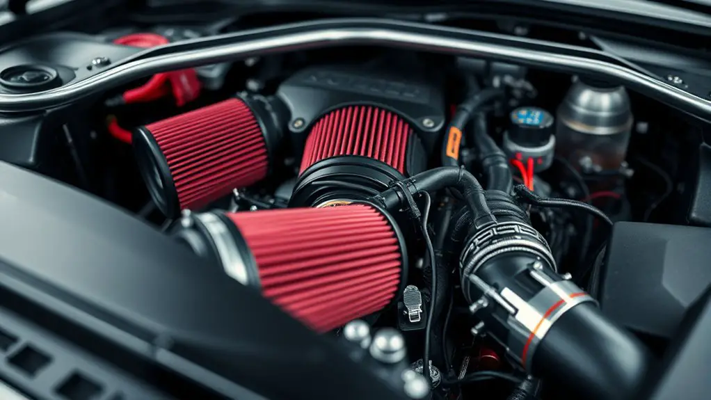
How to Avoid Unexpected Wiring Issues When Retrofitting Performance Air Intake
Plan your harness route from the start: map a straight, low-drag path that avoids heat, moving parts, and pinch points. Choose connectors and wire gauges with ample ampacity, and document every anchor point for future serviceability. Keep power and sensor runs separate and use single-point grounding to prevent noise. Shield cables properly, terminate shields at one end, and test continuity and voltages early. If you keep going, you’ll uncover more details to tighten reliability.
Planning the Harness Route for a Clean Installation
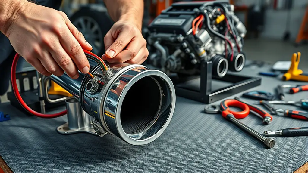
When planning the harness route for a clean installation, start by mapping the path with purpose: avoid heat sources, moving parts, and pinch points, and keep the harness away from exhaust routes and sharp edges. You’ll evaluate routing options and choose a straight, low-drag path that minimizes bends and tension. Mark anchor points that accommodate future serviceability without clutter. Prioritize protection: use harness materials rated for vibration and temperature, and shield conductors from chafing with sleeves or conduit where needed. Plan reliefs at connectors to reduce stress while allowing flex. Identify required grommets, clips, and mounts, and sequence the route to align with component spacing. Inventory installation tools and verify you have the right crimpers, pullers, and diagnostic aids for a clean job. Document the route for future work, noting any deviations. This approach builds reliability and preserves freedom of motion while keeping the system tidy.
Selecting Connectors and Wire Gauges for Compatibility
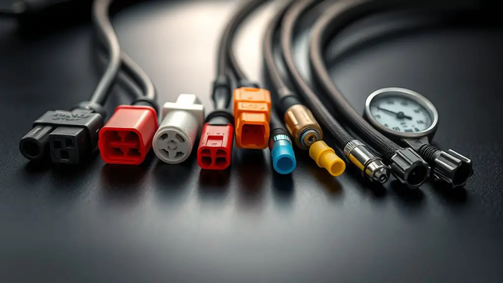
Choosing the right connectors and wire gauges is about matching current, voltage, and environment to the system’s demands. You’ll pick connector types that handle your expected currents with margin, avoiding tight fits that cause heat buildup or voltage drops. Start by mapping the load: peak amps, continuous draw, and startup surges. Then choose wire gauges that meet ampacity charts for your climate and routing, adding a headroom buffer for temperature rise. In parallel, select connectors with correct mating styles, housings, and locking mechanisms to resist vibration and moisture ingress. Always verify wire insulation compatibility with engine bay temps and chemical exposure, using insulation rated for the expected range. Color coding, consistent pinouts, and documented third-party part numbers reduce ambiguity during installation and future service. Document torque specs for crimp connections, and test continuity after assembly. This disciplined approach minimizes retrofit surprises and preserves reliability under demanding driving conditions.
Shielding, Grounds, and Noise Mitigation Strategies
Shielding, grounding, and noise mitigation start with a simple, deliberate plan: identify sensitive signals, known interference sources, and the worst-case pathways. You’ll map routes, then choose targeted fixes. Noise filtering and electrical shielding aren’t optional; they’re the core of reliable retrofits. Use short, direct paths for critical signals, and keep power and sensor wires separate from high-current runs. Ground loops vanish when you single-point ground and tie chassis at a single, purpose-built point. Shielded cables should be terminated properly, with shields tied to ground only at one end where feasible. Keep grounds dry, clean, and bonded to a common reference.
| Strategy A | Strategy B |
|---|---|
| Identify signals early | Isolate interference sources |
| Separate power from data | Use proper shielding topology |
| Single-point ground | Inspect terminations |
| Test for noise pre-install | Validate with a bench test |
Sensor Tuning and ECU Compatibility Checks
Sensor tuning and ECU compatibility checks follow directly from establishing clean signal paths and reliable grounding. You’ll verify that sensor calibration matches your hardware changes, then confirm ECU updates align with the new intake flow and intake air temperature signals. Approach this systematically: map each sensor to its corresponding input, check wiring integrity, and validate data against real-world readings. If you spot drift, recalibrate before running tests to avoid cascading faults.
- Ascertain sensor calibration reflects the new intake configuration and airflow characteristics
- Confirm ecu updates incorporate updated sensor ranges, fault codes, and fuel trims
- Validate all A/D channel references, wiring harness continuity, and ground integrity before live testing
Keep notes on calibration values, ECU version, and any learned adaptations. This disciplined check protects reliability, reduces tirerome tweaks later, and preserves the freedom to push performance with confidence.
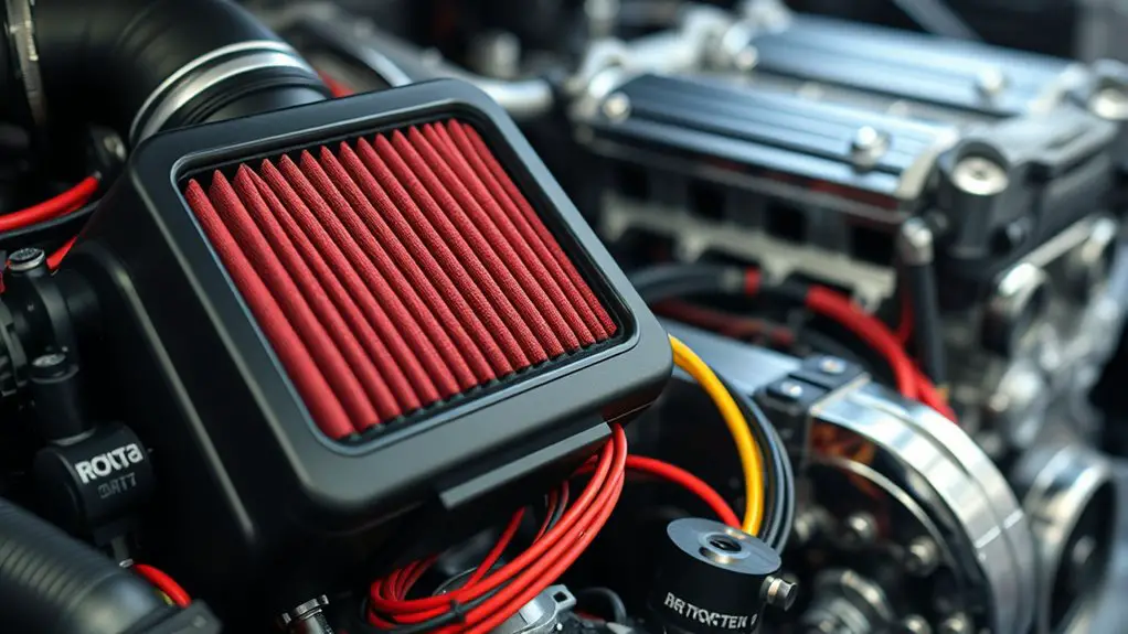
Fitment Tests and Troubleshooting Common Wiring Issues
Fitment tests verify that the intake and sensors physically align with your vehicle’s layout, wiring harnesses, and connectors without interfering with stock components. You approach this step with a plan: check clearance, tighten fittings, and confirm no chafing or heat exposure. Next, reference wiring diagrams to map sensor feeds, power, and grounds, noting any color-code changes the retrofit introduces. When you notice tight spaces, reroute harnesses along stock paths, avoiding sharp bends that degrade signals. Conduct continuity checks on each circuit and document expected voltages before powering up. If a sensor reads out of spec, re-seat connectors and recheck harness spacings, then verify ECU communication with a diagnostic scan. Troubleshooting techniques emphasize isolation: disconnect as needed to confirm which component triggers fault codes. Finally, perform road testing in a controlled environment, logging any intermittent faults. With careful documentation and disciplined checks, you minimize surprises and preserve reliability while maintaining freedom in your build.
Frequently Asked Questions
How Do I Identify Hidden ECU Pins During Retrofits?
You identify hidden ECU pins by reverse-engineering the wiring safely: start with the factory pinout, then use a multimeter to trace ground and power rails, and confirm signal lines with a wiring diagram resources source. Look for connector housings and back-probe techniques, labeling each pin as you go. ECU pinout identification takes patience. Maintain a clean, documented approach, test points, and reference reputable wiring diagram resources to avoid mistakes.
What’s the Best Way to Test for Parasitic Draw After Install?
You should start by verifying parasitic draw, then choose testing methods that fit your setup. Disconnect nonessential loads, set a precise ammeter in series, and monitor baseline current with the engine asleep. Use multiple trials, logging every variation, and compare against manufacturer specs. If you see excess draw, isolate circuits one by one, document findings, and re-test after fixes. Maintain focus on safe, repeatable testing methods to protect performance and freedom.
Can Aftermarket Sensors Require Flash or Reflash of ECU?
Yes, some aftermarket sensors require a flash or reflash of the ECU to guarantee proper compatibility and reliable data. You should verify aftermarket compatibility with your ECU’s tuning capabilities and the sensor calibration specifics before installation. Plan for a calibrated setup, and budget time for testing and potential reflash. Approach methodically: confirm wiring, adapters if needed, confirm sensor outputs, and recheck parasitic draw after calibration to avoid surprises.
How Do I Prevent EMI From Nearby Aftermarket Electronics?
You, like a careful navigator, prevent EMI by applying solid Electromagnetic shielding, using proper Grounding techniques, and isolating lines from noise sources. Locate sensitive wires away from aftermarket electronics, route them in shielded conduits, and keep signal interference to a minimum with twisted-pair runs and thoughtful separation. Use insulated cables, seal gaps, and verify with a test sweep. Trust the process and respect insulation materials, so your setup remains free, fast, and dependable.
Are There Legal or Warranty Implications of Wiring Changes?
Yes, there can be warranty limitations and legal compliance considerations when you wire changes. You’ll want to document everything and restore OEM components if needed to avoid voiding coverage. Check your warranty terms for exclusions and keep receipts for aftermarket parts. Follow local regulations and vehicle codes, and guarantee electrical work isn’t bypassing safety features. If in doubt, consult the dealer or a licensed technician to preserve warranty protections and stay legally compliant.