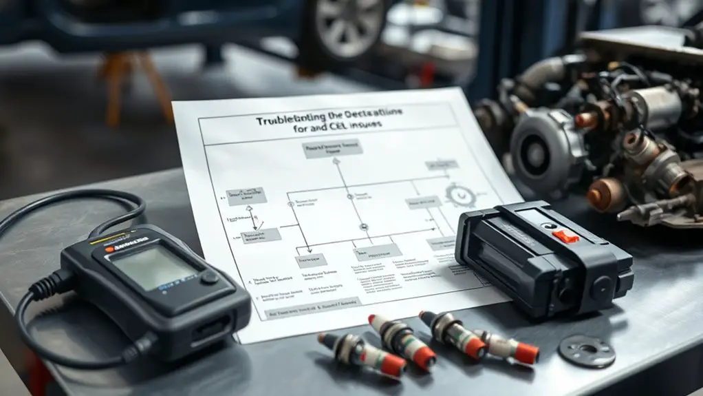
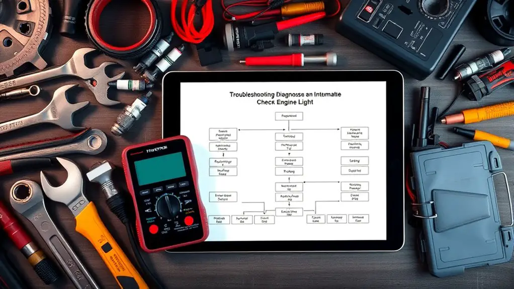
How to Build a Troubleshooting Flow for Intermittent CEL
You’ll build a repeatable, data‑driven flow to tame intermittent CELs. Start with a clear problem statement and log every action. Use a structured checklist to map symptoms to likely faults, prioritizing tests that quickly separate candidates. Rely on live readouts, freeze-frame data, and trend logs to confirm or refute causes. Verify sensor connections, power and ground integrity, then perform targeted functional and bench tests. With a verifiable verification plan, you’ll pinpoint fixes and track outcomes—and you’ll uncover more insights as you go.
Diagnosing Intermittent CEL: Why Symptoms Are Unreliable
Intermittent check-engine lights are tricky because the fault may not appear every drive, and symptoms alone can mislead you about a real issue. You’ll learn to separate observation from conclusion. Rely on repeatable tests rather than single incidents. Track when the light activates, how long it stays, and what you were doing—driving mode, load, temperature, and RPM matter. Intermittent symptoms can mask a failing sensor, loose connector, or parasitic drain, so don’t assume cause from appearance. Use a systematic checklist: confirm code history, note freeze-frame data, and verify that repairs or maintenance didn’t introduce a new variable. Expect unreliable diagnostics when signals change with humidity, aging wiring, or intermittent corrosion. Document patterns, then test under controlled conditions to reproduce or rule out faults. By focusing on data, not vibes, you protect your freedom to diagnose efficiently and avoid chasing phantom problems.
Mapping Symptoms to Potential Faults: A Structured Approach

You’ll map symptoms to potential faults using a structured approach: first link symptoms to probable causes, then prioritize the most likely ones, and finally plan test-result mappings to confirm or rule them out. This keeps you focused on Symptom-to-Fault Linkage, prioritization, and how tests will validate each step. The goal is a concise flow that guides subsequent diagnostic actions with clear, testable outcomes.
Symptom-to-Fault Linkage
Symptom-to-fault linkage is a structured process for translating observed engine behaviors into credible fault candidates. You link each symptom to plausible causes through symptom analysis, then filter by feasibility, history, and detectable patterns. Begin with clear observations: timing, duration, intensity, and context. Then map to common fault families—fuel, ignition, air, sensors, actuators—avoiding premature conclusions. Use a concise checklist to document corroborating signs, test opportunities, and potential diagnostics. Maintain traceability: note how each symptom supports or refutes a candidate. Prioritize fault identification by confirming consistency across events and ruling out external influences. Employ simple, repeatable tests to distinguish between similar causes. This disciplined approach reduces guesswork, speeds resolution, and sustains freedom to explore alternative explanations without bias.
Prioritize Likely Causes
To prioritize likely causes, start by ranking candidate faults from most to least probable based on symptom features, frequency, and history. You structure your assessment around likely fault scenarios, then weight each against observed patterns, driving down noise. Use a concise matrix: symptom matches, confidence, and impact, updating as you gather data. Consider common sensor issues first, since they frequently drive intermittent CELs, but avoid overgeneralizing. Separate high-likelihood faults from uncertainties, so you can allocate testing effort efficiently. Document rationale for each ranking to support repeatability and learning. Maintain discipline: test only what matters for the top tiers, then expand if results warrant it. Your goal is a disciplined, transparent, actionable prioritization that guides subsequent verification steps.
Test-Result Mapping
Building on the prioritized list of likely faults, this section maps observed test results and symptom features to the most probable causes in a structured way. You’ll link test result significance to each symptom, spotting how results reinforce or weaken candidates. Focus on result correlation across tests, so patterns emerge rather than isolated data points. Use a consistent mapping with clear thresholds, units, and criteria, enabling repeatable conclusions. This approach reduces ambiguity, guiding you toward the right fault faster.
| Symptom/Result | Probable Cause |
|---|---|
| Sensor voltage drop | Wiring fault or sensor failure |
| Rich/lean indicator | MAF or oxygen sensor discrepancy |
Prioritizing Tests: Which Checks Bring Clarity Fast

When diagnosing an intermittent check engine light, start by prioritizing checks that quickly confirm or rule out major failure modes. You want clarity fast, so map checks to likely faults rather than breadth. Begin with high-risk systems that produce visible symptoms or costly repairs if left unchecked. Use test prioritization to sequence actions by impact and probability, not by convenience. Apply efficiency metrics to gauge every step: time-to-answer, repeatability, and skip-rate for redundant tests. If a test answers nothing, move on; if it confirms a fault pattern, drill deeper there. Favor checks that either eliminate large swaths of unknowns or point decisively to a single culprit. Document decisions concisely, noting why a test mattered and how it changed the plan. Keep the flow lean: avoid duplicate measurements, limit tool switching, and cap exploration time per area. Your goal is actionable clarity, faster containment, and an adaptable framework for future intermittent cases.
Data-Driven Clues: Using Live Readouts and Scan Tools
Live readouts and scan tool data are the fastest sources for confirming or ruling out faults once you’ve narrowed the field. You’ll rely on live data analysis to spot anomalies in real time, not after the fact. Focus on commanded values, sensor trends, and fault code quirks; look for consistency between behavior and data, not bright ideas. When you observe a mismatch, pause, verify the stimulus, and separate transient blips from persistent deviations. Scan tool usage becomes a disciplined workflow: capture PID lists, log values, and compare across sessions to reveal pattern shifts. Prioritize data quality—tallied, time-stamped, and free of Gibbs noise. Document each finding succinctly and link it to a potential fault class. Use thresholds and allowed ranges as guardrails, not gospel. This approach keeps you in control, moving decisively toward the root cause while maintaining the freedom to adapt your plan as data evolves.
Verifying Sensor Connections and Power/Ground Integrity
Even a perfect plan can fail if a sensor isn’t properly connected or powered; you’ll start with a calm, methodical check of obvious hardware issues. Verify sensor integrity by inspecting connectors for bent pins, corrosion, and damaged housings, then confirm pins seat fully and straight. Move to connection verification by tracing power, ground, and signal paths from the ECU or harness to each sensor, noting any loose, cracked, or abraded wires. Use a known-good ground reference and check for consistent voltage ranges across the operating spectrum; document any dips, spikes, or intermittent drops. Re-seat connectors with firm, even pressure and avoid torqueing the pins. When in doubt, swap a suspect harness or sensor with a known-good unit to isolate the failure mode. Record findings clearly, with timestamps and tool readings. This disciplined approach protects sensor integrity and short-circuits uncertainty, enabling you to progress toward reliable diagnostics rather than guesswork. connection verification matters, keep it tight and verifiable.
Narrowing Down With Functional Checks and Bench Tests
Functional checks and bench tests are the next, controlled step to isolate faults without relying on suspect field conditions. You apply functional diagnostics to separate symptoms from root causes, using repeatable stimuli to reveal consistent behavior. Bench testing lets you recreate loads, signals, and timing in a known-good environment, cutting exposure to EMI, wiring quirks, and intermittent contact issues. Approach is methodical: define what you measure, how you measure it, and what constitutes acceptable variance. Document results as you go, so you don’t confuse symptoms with fixes. Table below clarifies inputs, expected outputs, and decision points.
| Input/Signal | Expected Output/Behavior | Action Trigger |
|---|---|---|
| Sensor signal A | Stable within spec | Proceed if in-range |
| Actuator response B | Timely, repeatable | Replace if out-of-range |
| ECU response C | Consistent diagnostic data | Log and compare |
| Power rail D | Stable voltage under load | Investigate if sag |
| Ground integrity E | Low impedance | Re-test after fixes |
Documenting a Repeatable Troubleshooting Flow
How can you guarantee a repeatable troubleshooting flow is both usable and verifiable? You build clear, repeatable steps you can follow under varying conditions. Start with a concise problem statement, then outline the sequence you’ll execute, not just the results you expect. Embrace troubleshooting documentation that records inputs, decisions, and outcomes; this becomes your audit trail and training aid. Keep each step atomic: a single action, a single check, a defined pass/fail criterion. Use objective metrics and timeboxes to reduce drift. Incorporate a lightweight validation loop: run the same test under similar conditions, compare results, and note discrepancies. For communication, tie each action to evidence and rationale, so anyone can reproduce your flowchart creation and interpretation. Maintain versioning of the flow, and store the artifacts in a centralized repository. Finally, couple the flow with simple templates for notes, screenshots, and logs to sustain consistency over time.
Translating Findings Into Action: Fixes and Verification
You’ll translate findings into concrete actions by outlining exact fixes tied to symptoms and data. Implement fixes systematically, documenting each change and its expected impact. Then verify by executing reproduction steps to confirm the intermittent CEL behavior is resolved.
Translating Findings to Actions
Once you’ve gathered the data, translate each finding into concrete, testable actions to fix the intermittent CEL issue and verify results. Start with actionable insights that map directly to observed symptoms, not guesses. Prioritize changes by their likelihood of addressing the root cause and their impact on system stability. Document expected outcomes, required tools, and anticipated failure modes for every action. Create a tight verification plan: define success criteria, repeatability, and clear pass/fail thresholds. Use small, incremental changes to isolate effects, avoiding scope creep. Maintain traceability by linking actions to specific findings, ensuring you can backtrack if results diverge. This disciplined approach preserves your freedom by providing transparent, controllable steps toward solution.
Implement Fixes Systematically
To implement fixes systematically, translate each finding into a concrete, testable action and map it to the observed symptom, starting with the low-hanging, high-impact items. You’ll pair fixes with clear criteria, enabling quick validation and traceability. Use concise implementation strategies that prioritize minimal risk while maximizing return, then document outcomes to refine your plan. Focus on repeatable steps, measurable thresholds, and rollback options so you can pivot if needed. Maintain a living list of hypotheses and their success signals, updating as evidence evolves. This approach supports systematic fixes that are easy to audit, reproduce, and scale.
| Symptom | Action | Expected Outcome |
|---|---|---|
| Impact | Priority | Verification Method |
| Idle Noise | Inspect connectors | Noise reduction |
| Sensor Drift | Calibrate SPIs | Consistent readings |
| Fuel Trim | Update maps | Stabilized mpg |
Verify via Reproduction Steps
When you verify findings, start by reproducing each symptom exactly as observed, documenting the steps, timing, and environment to confirm consistency. Use controlled reproduction methods to isolate the trigger, then repeat across multiple cycles to validate stability. Record any variance in readings, codes, or behavior, noting the exact state of power, temperature, and workload. Compare results against baseline expectations to identify drift or intermittent coupling. Maintain a lean log that links every reproduction to a concrete expectation, so later fixes align with verified causes. Define your testing environments clearly—one with minimal variables, one stress-tested—then cross-check outcomes. Avoid assumptions; confirm with measurable, repeatable criteria. This discipline turns findings into actionable fixes and reliable verification.
Frequently Asked Questions
How to Handle Intermittent CEL With No Codes?
You handle intermittent CEL with no codes by staying systematic. First, observe patterns and document recent driving conditions. Then use diagnostic strategies like data logging, freeze-frames, and scan tool live data to spot anomalies. Check basics: ignition, fuel, air, and vacuum leaks. Evaporative system tests and wired impedance can reveal hidden faults. Don’t overlook hidden faults in sensors. If codes remain absent, repeat tests under varying loads, and trust trend analysis to confirm intermittent issues.
Can Weather Affect Intermittent Sensors and How to Test?
Weather can affect intermittent sensors; yes. You’ll want to assess weather impact on readings and test under varied conditions. Start by noting ambient temperature, humidity, and exposure if sensors are outdoors. Check sensor reliability with controlled cycles, swap with known-good units, and log every change. Use diagnostic tests that isolate the sensor circuit from the ECU, verify wiring integrity, and re-check after weather shifts. This systematic approach preserves sensor reliability while you troubleshoot.
How to Differentiate Phantom Codes From Real Faults?
Phantom codes are misfires of interpretation, not real faults; you’ll distinguish them by repeating checks, comparing freeze frames, and confirming with road tests. Use code interpretation and fault analysis to separate noise from truth: verify with alternate sensors, scan histories, and consistency across power cycles. If a single code vanishes after reset, suspect phantom data. Document patterns, rule out wiring, and corroborate with actual performance changes before you label a fault.
What if Tests Contradict Scan Tool Readings?
Like a tightrope walker crossing a fault line, you trust method over mood. If tests contradict scan tool readings, you keep calm and rely on test discrepancies to guide you. Revisit diagnostic protocols, recreate conditions, and log results meticulously. Prioritize repeatable data, adjacent sensors, and grounding checks. You don’t chase certainty; you chase consistency. Narrow down possibilities, document every step, and decide only when observations align. Your system deserves disciplined, reproducible conclusions.
When to Replace Components Rather Than Re-Test?
You should replace components when you’ve exhausted a reasonable diagnostic strategy and evidence points to failure, not just disagreement with test results. If a part’s lifespan is short or you’ve repeated tests with consistent failure modes, swap it. When reliability improves after replacement and re-testing confirms, you’ve validated the decision. Maintain a clear diagnostic strategy, log results, and weigh risk, cost, and downtime. Trust component lifespan data but verify with practical testing.