How to Build a Troubleshooting Flow for No Communication With ECU
Start by defining the no-communication symptom clearly, then build a step-by-step flow that verifies power and ground, inspects the data link harness, and checks shielding and continuity. Gather essential tools, documentation, and a tested workflow. Confirm clean power, solid grounds, and healthy battery voltage before testing. Inspect fuses, relays, and the main loom; verify data-link integrity and protocol settings. Test ECU communication with reliable tools, document results, and create repeatable steps for future issues. You’ll uncover practical, actionable steps as you proceed.
Understanding the No-Communication Symptom
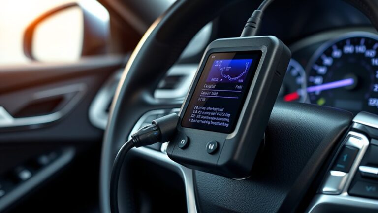
A no-communication symptom means the ECU isn’t exchanging data with the diagnostic tool or other control modules as expected. You observe a lack of handshake, stalled data streams, and missing or stale diagnostic trouble codes. In this scenario, no communication causes uncertainty about function, rendering quick decisions difficult. You should verify basic signaling integrity first, then assess the communication protocol and network topology. Symptom identification hinges on recognizing patterns across interfaces: CAN, LIN, K-line, or Ethernet. Document whether the symptom appears under load, at startup, or during idle, and note any intermittent behavior. Consider environmental and power factors that could mask or amplify the issue, such as voltage dips or ground faults. Use a disciplined approach to isolate the fault: rule out wiring, connectors, and harness damage before suspecting a faulty ECU. This method supports a clear, evidence-based path to resolution while preserving your autonomy and confidence.
Gather Essential Tools and Documentation

Start by listing the essential tools you’ll need: a reliable multimeter, scan tool, and basic oscilloscope or data-logger, plus any ECU-specific adapters. Keep a documented checklist of each item’s specifications, calibration status, and expected ranges to reference during testing. Pair this with a curated set of documentation resources—service manuals, wiring diagrams, and known-good reference data—to guide diagnosis and guarantee you verify steps with evidence-based procedures.
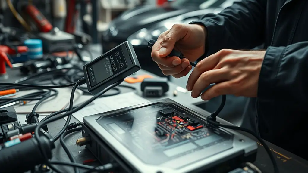
Essential Tools Overview
To troubleshoot ECU communication effectively, you’ll need a core set of tools and the right documentation: a diagnostic interface suited to your ECU, a reliable laptop or tablet with compatible software, and secure data cables that expose the essential protocols used by your system. With these in hand, you can verify physical connections, power, and ground references, then move to signal integrity checks. Prioritize proven diagnostic equipment from reputable vendors to minimize variability and maximize repeatable results. Maintain a compact toolkit: multimeter for continuity, a USB dongle for logging, and a basic oscilloscope or logic analyzer if you work with fast buses. Document configurations, test steps, and results to support decisive troubleshooting decisions and reproducible workflows.
Documentation Resources Checklist
With the right tools in hand from the prior section, you’ll establish a solid backbone for diagnosing ECU communication. In this documentation resources checklist, you focus on concrete assets that travel with you: manuals, schematics, fault code references, and a reliable logging app. Maintain documented version control of software builds, calibration files, and ECU software integrity checks to prevent mismatch errors. Adopt documentation best practices: concise notes, timestamped entries, and consistent terminology. Build a portable, searchable repository you can access offline, plus a centralized troubleshooting checklist that guides you through steps and expected outcomes. Prioritize organized wiring diagrams, pinout references, and test procedure summaries. This clarity supports freedom to troubleshoot efficiently without guesswork, ensuring repeatable, evidence-based decisions.
Verify Power, Ground, and Battery Health
Ensuring clean power, solid ground, and healthy battery voltage is foundational before diagnosing ECU communication issues; if any of these are out of spec, all signals can appear faulty. You’ll verify power distribution across the harness, ensuring supply rails meet specifications under load, not just at idle. Check for parasitic drains and verify the battery can sustain cranking and ECU voltage during key-on. Inspect ground integrity by testing chassis and engine grounds for low resistance, clean contact points, and solid return paths; a flaky ground can masquerade as data faults. Measure voltage drop along grounds with the system energized to reveal hidden resistance. Use a reference chart to compare observed values against manufacturer tolerances, noting any variance that could destabilize communications. If readings lie outside acceptable ranges, correct the conditioning before proceeding. Document results, since repeatability matters. This disciplined, evidence-based approach keeps your focus on reliable power distribution and ground integrity as you advance.
Inspect Fuses, Relays, and Power Looms
Start with a quick fuse and relay check to confirm they’re intact and seated properly. Inspect the main power loom for signs of wear, corrosion, or pinched wires that could interrupt ECU power. Document any findings and proceed to targeted tests to confirm continuity and voltage at the control modules.
Fuse and Relay Check
Begin with a quick visual and functional check of the fuse box, relays, and the power loom to confirm they’re intact and seated properly. You’ll examine fuse identification labels, confirm fuse amperages match spec, and look for signs of damage or corrosion. Then test each relay for proper operation—listen for clicks, feel for distinct actuator movement, and verify continuity when energized. Remove and reseat suspicious fuses or relays to rule out poor contact, and replace any burned, cracked, or discolored components. Document findings, noting which items pass or fail. By isolating ignition, power, and communication circuits, you reveal where a fault could interrupt ECU access. This step supports a calm, evidence-based approach and strengthens your ability to diagnose without overreaching assumptions. Relays functionality and fuse identification guide your next, targeted checks.
Power Loom Inspection
Power loom inspection ties directly into your fuse and relay checks by tracing the path from ignition power through the loom to the ECU. You’ll verify power availability at critical loom junctions, confirm continuity along harness segments, and inspect connector integrity. Start with loom wiring diagrams to identify power feed and ground routes, then test each segment with a multimeter or scope, watching for voltage drop under load. Inspect for chafed insulation, corrosion, or pin damage at loom connectors, and note any intermittent failures. Compare observed conditions against power loom types used in your vehicle, and document suspected failure modes. Use clear, repeatable steps to isolate faults, replacing damaged sections and rechecking all circuits. This keeps your flow evidence-based and focused on reliable, safe restoration of ECU communication.
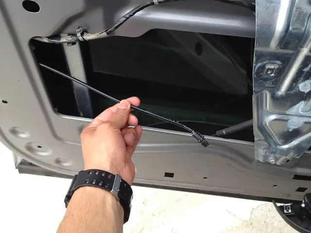
Check Data Link Harness Integrity and Shielding
If you suspect data link issues, start by inspecting the harness for integrity and shielding, since poor connections or compromised shielding can induce intermittent comms problems. Begin with a visual check for damaged insulation, cracked connectors, and pin corrosion, then tug gently to confirm secure latches. Document harness runs, noting any bends or kinks that could stress conductors. Move to continuity testing on each wire segment, using a multimeter to verify expected resistance without shorts to adjacent lines. Look for pin-to-pin isolation and confirm shield braid continuity back to ground, as grounding faults can mirror data errors. Assess shielding effectiveness by testing for EMI pickup along critical runs; shielded sections should maintain stable signal in the presence of noise. Replace or repair damaged sections, reseal harness points, and recheck with functional tests. Conclude with a short-field test to validate stable comms before advancing. harness testing, shielding effectiveness.
Align Protocol Settings and ECU Configuration
Having verified the data link harness, you can proceed to align protocol settings and ECU configuration to guarantee consistent communication. You’ll verify baud rate, parity, stop bits, and protocol mode, then adjust ECU parameters to match. If a protocol mismatch is detected, correct both ends to the same standard, ensuring timing and framing align. Confirm that the ECU’s diagnostic session and mode align with the tester’s capabilities, and disable any conflicting security or encryption features during setup. Record initial conditions and outcomes for traceability, then re-test after each change. This approach prioritizes ECU compatibility and predictable behavior, not ad‑hoc tinkering.
| Step | Action | Expected Result |
|---|---|---|
| 1 | Check baud/parity | Aligned settings |
| 2 | Match protocol mode | Consistent framing |
| 3 | Align ECU params | Compatibility achieved |
| 4 | Validate baseline | Stable communication |
If issues persist, re-evaluate wiring and re-check the same settings to close a protocol mismatch efficiently.
Test Communication Line With Diagnostic Tools
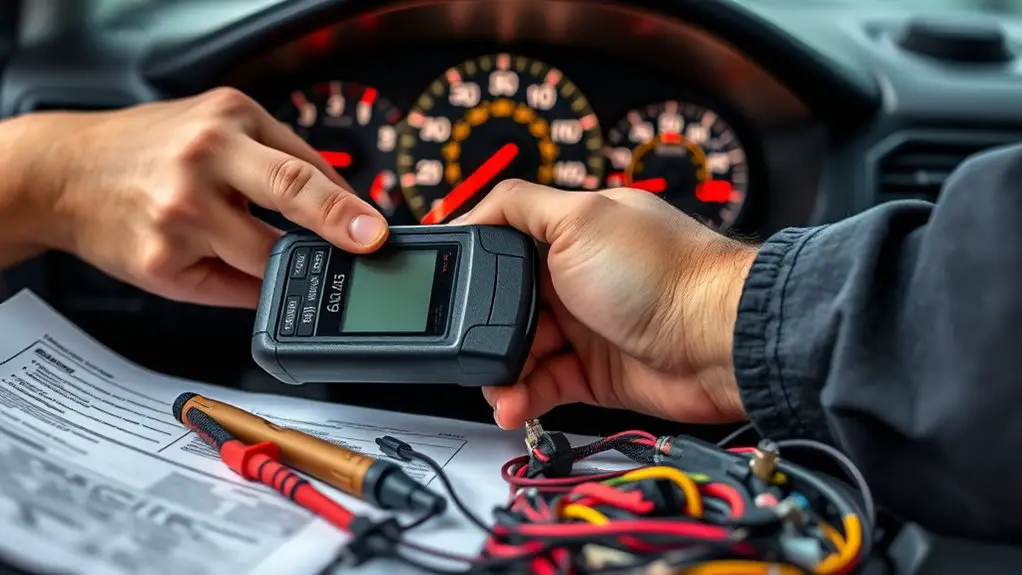
To test the communication line, start with a baseline diagnostic sweep using your preferred diagnostic tool to confirm link integrity, signal quality, and error counters. You’ll verify that the line responds within expected timing windows and that no persistent faults show in the interface. Next, compare the observed data against documented communication protocols to spot deviations early. Use diagnostic scanners to log baud rate, error frames, and frame parity; document any anomalies for correlation with ECU behavior. Ascertain you’re working with a clean ground reference and stable power during the test.
- Confirm link handshake succeeds and remains stable
- Check for unexpected error counters or retry rates
- Validate timing and message framing against protocol specs
- Record tool outputs for trend analysis over multiple cycles
Assess ECU Health and Possible Faults
Evaluating ECU health hinges on systematic fault detection and data-driven interpretation. You’ll assess signals, power, grounding, and sensor integrity to identify faults without assumptions. Start by checking for fault codes and recent fault history, then verify that the ECU receives clean CAN or serial data. If you see inconsistent responses, re-test with controlled inputs to separate sensor drift from ECU fault. Use ECU diagnostics to verify calibration, timing, and communication protocol compatibility. Document each finding with objective measurements and observable behavior. If faults persist, consider whether environmental factors or wiring integrity could be at play. Prioritize safe, repeatable tests and avoid over-interpretation of isolated anomalies. The goal is a concise, evidence-based view of health, guiding next steps in your flow.
| Step | Action |
|---|---|
| 1 | Retrieve fault codes and history |
| 2 | Inspect power, ground, and sensors |
| 3 | Validate data integrity |
| 4 | Reproduce with controlled inputs |
| 5 | Correlate findings with diagnostics |
Document Findings and Create a Repeatable Workflow
Document findings with precise, objective notes and capture them in a repeatable workflow. You’ll build a clean record that’s easy to audit, repeat, and share, reducing guesswork in future checks. Focus on reproducible observations and time-stamped entries, then translate them into actionable steps. By documenting observations consistently, you’ll create templates you can reuse across cases, speeding diagnostics while maintaining integrity.
- Use structured fields for symptoms, conditions, tools used, and results
- Attach relevant logs, screenshots, and measurements for context
- Record decisions with rationale to show why each path was chosen
- Store the workflow in a central, versioned location for easy updates
This approach supports freedom from ambiguity, enabling you to pivot swiftly when new data arrives. Keep templates lean, review them after every test, and refine language to reduce misinterpretation. The result is a repeatable process you can trust and teach, not just rely on.
Frequently Asked Questions
How Do Environmental Conditions Affect ECU Communication Reliability?
Like a clockwork compass, you’ll feel the QA snap when conditions shift. Temperature fluctuations can slow or corrupt ECU comms, expanding retry timers and increasing error rates. Electrical interference, from ECU grounding to harness noise, destabilizes signals and causes retries or drops. You’ll test with controlled temps and shielded paths, log bit errors, and verify grounding. Your method remains evidence-based: isolate the variable, measure impact, and document tolerances before proceeding.
Can Intermittent Faults Mimic a No-Communication Symptom?
Yes, intermittent faults can mimic a no-communication symptom. You’ll want to verify with diagnostic tools that signals are stable enough to register, then rule out wiring or connector issues, power supply fluctuations, and ECU grounding. Use diagnostic tools to monitor live data and check for sporadic interrupts. Document patterns, reproduce when possible, and distinguish true no-communication from transient glitches. This evidence-based approach helps you isolate root causes and prevent misdiagnosis.
What Are the Best Practices for Data Log Retention and Review?
Data log retention best practices center on clear policies and accessible archives. You should define data log storage formats, retention durations, and secure offsite backups. Regularly review logs using log review techniques like trend spotting and anomaly detection. Schedule automated reports, flagging gaps or corrupt files. Keep metadata, timestamps, and versioning intact. Regularly rotate storage, verify integrity, and document findings. This approach supports freedom to act quickly while maintaining rigorous, evidence-based troubleshooting.
How to Verify ECU Software Integrity Without Replacement?
You verify ECU software integrity by performing ECU software validation using checksums, cryptographic signatures, and current version comparisons, then cross-check firmware against official release notes. Follow firm firmware update procedures to fetch a validated image, apply it, and re-check hashes post-install. If anomalies appear, rollback isn’t replacement-driven; instead, revalidate integrity with a fresh image. Document results, retain logs, and repeat with independent verification to guarantee continued trust and freedom in your system.
When to Escalate to OEM Diagnostic Procedures or RMA?
When you’re deciding, escalate to OEM diagnostic procedures or initiate an RMA when symptoms persist after your checks, when fault codes remain unresolved, or when safety or warranty concerns arise. You should follow OEM procedures, and apply RMA criteria, if evidence shows hardware fault or unreliable ECU response. You escalate decisively, document findings, and preserve logs. You stay disciplined, evidence-based, and concise, ensuring every step aligns with OEM guidelines and your organizational risk tolerance.