How to Build a Troubleshooting Flow for Noisy CAN Bus
To build a troubleshooting flow for a noisy CAN bus, start by mapping common noise sources like switching supplies, motor drives, improper termination, and cable layout. Measure signal integrity with an oscilloscope or CAN analyzer to capture timing, voltage levels, and frame shifts. Use a systematic fault-isolation flow: reproduce symptoms, form testable hypotheses, and compare against known-good traces. Define clear pass/fail criteria for jitter and bit errors, then document changes. If you keep exploring, more actionable steps follow.
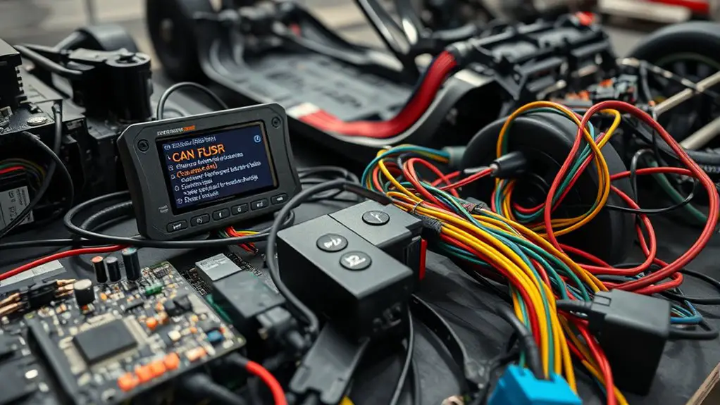
Understanding Common Noise Sources on CAN Bus
Common noise sources on a CAN bus come from both electrical and environmental factors. You’ll identify how electromagnetic interference and ground loops inject distortion into signals, then categorize sources by location and impact. Electrically, look for transients from switching power supplies, motor drives, and nearby high-current devices, plus improper termination that reflects reflections. Environmentally, consider cable management, proximity to fluorescent lighting, and vehicle chassis conditions that alter grounding. You’ll map paths where noise couples into CAN wires—radiated, conducted, and via ground impedance. Practice disciplined inspection: verify correct bus termination at both ends, confirm twisted-pair integrity, and ascertain shield usage aligns with your chassis ground strategy. You’ll isolate potential EMI by rotating equipment, testing with shielded probes, and temporarily rerouting cables. You’ll document findings with consistent naming, measurements, and a plan for mitigation. Ground loops and EMI are your primary suspects; address them methodically to restore reliable communication.
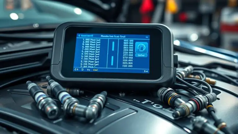
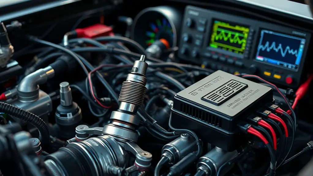
Measuring and Analyzing CAN Signals Effectively
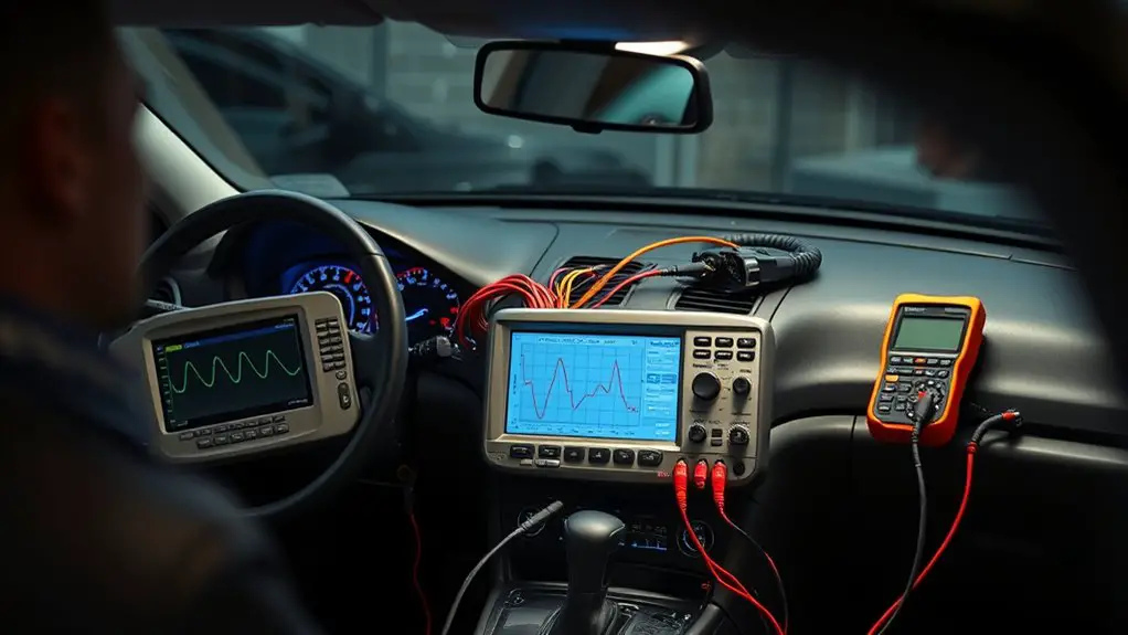
So now that you’ve mapped the main noise sources, you’ll focus on measuring and analyzing CAN signals with a precise, methodical approach. You’ll verify signal integrity first, then apply targeted measurement techniques to reveal real faults without guesswork. Use an oscilloscope or CAN analyzer to capture bus timing, voltage levels, and recessive/dominant shifts, keeping probes grounded and shielded. Markers help you align frames and identify jitter, bit-stuff errors, and asymmetries. Compare as-built traces to nominal CAN specs, adjusting bandwidth and sampling rate to avoid aliasing. Document findings succinctly and repeat measurements after any topology change. The goal is repeatable clarity, not loud noise.
| Step | Tool or Technique | Focus Area |
|---|---|---|
| 1 | Oscilloscope | Timing & shifts |
| 2 | CAN analyzer | Frame-level data |
| 3 | Probes & grounding | Signal integrity |
| 4 | Reference comparison | Baseline validation |
| 5 | Documentation | Reproducibility |
Systematic Diagnostic Flow for Fault Isolation
Systematic fault isolation follows a disciplined sequence: define the symptom, reproduce it under controlled conditions, and establish a testable hypothesis. You approach fault identification by outlining observable effects, then separating candidate causes into groups (physical layer, signaling, or protocol handling). Begin with precise measurements: timing jitter, bit error rate, and voltage thresholds, recorded under repeatable loads. Validate signal integrity with comparative traces from known-good and stressed scenarios, noting where distortions emerge. Develop a concise hypothesis tree: is noise driven by cables, connectors, terminations, or transceiver behavior? Use controlled replication to confirm or refute each branch, updating conclusions as data arrives. Maintain objective criteria for success: a demonstrable, repeatable condition that aligns with a single causal path. Document all steps, decisions, and pass/fail criteria. You’ll stay focused on isolating the fault while preserving system functionality, avoiding assumptions not substantiated by evidence. A disciplined, data-driven mindset accelerates reliable fault identification and preserves design freedom.
Tooling and Techniques for Reproducible Tests
To enable reliable fault isolation in noisy CAN bus systems, you need reproducible tests that yield repeatable, actionable data. Tooling and techniques center on stable baselines, controlled perturbations, and clear measurement criteria. You balance test equipment choice with signal integrity awareness to avoid masking faults or creating false positives.
To enable reliable fault isolation, use repeatable tests, stable baselines, and clear measurement criteria.
- Assemble a minimal, reusable test rig: a known-good transceiver, a controllable load, and a calibrated scope or logic analyzer to capture CAN high/low changes and timings.
- Define repeatable scenarios: baseline traffic, injected faults, and environmental variance, recorded with synchronized timestamps and labeled metadata for quick comparison.
- Document pass/fail criteria: objective thresholds for bit error rate, jitter, and amplitude, plus pass criteria for each test step to guarantee consistent outcomes.
Key benefits include rapid fault isolation and reproducible results, enabling you to iterate with confidence. Always verify signal integrity after setup changes; faulty wiring or connectors can masquerade as real faults.
Documenting Findings and Preventing Recurrence
Documenting findings and preventing recurrence is about turning results into actionable knowledge you can reuse. You’ll capture what happened, how you diagnosed it, and why the failure occurred, in a structured, repeatable format. Begin with a concise incident summary, then list the symptoms, measurements, and observed patterns that guided your reasoning. Record the root cause and the evidence supporting that conclusion, avoiding vague language. Map each finding to concrete actions you took, including the tests run, the configurations changed, and any measurements captured at each step. Next, define preventive measures to stop recurrence: update checklists, adjust thresholds, implement stricter cabling or shielding practices, and apply software debouncing or filtering only where appropriate. Emphasize validation: confirm the fix in a controlled test and document the outcome. Finally, store the documentation where teammates can access it, and link it to reusable templates for faster future investigations.
Frequently Asked Questions
How Do I Prioritize Faults After Multiple Noise Sources?
You prioritize faults by immediate impact, then frequency, then complexity. Start with fault classification to separate critical system faults from nuisance noise, triage highest risk first. Next assess noise mitigation chances: tackle sources you can control, then iterate measurements. Assign weights: safety-critical, throughput, and uptime. Use a kill-switch approach if live data degrades. Document results, update thresholds, and revalidate. You’ll gain order, speed, and clarity while keeping your system audaciously free from chaos.
What Is Acceptable CAN Bus Jitter in Automotive Networks?
Acceptable jitter in automotive CAN bus varies by standard, but you’ll typically expect under a few hundred microseconds for bit timing in standard configurations. You should verify against automotive standards like ISO 11898 and your network’s baud rate. In practice, measure worst‑case jitter under load, document margins, and design with guards for EMI. If jitter climbs, reassess bus capacitance, terminators, and transceiver quality to keep performance within spec, safely maintaining control.
Can Passive Monitoring Introduce Additional Noise?
Yes, passive monitoring can introduce additional noise, though usually minor if done right. You’re watching, not driving the bus, so keep probes high-impedance and physically separated from power rails. Consider how passive analysis can pick up cadence shifts or extra noise sources from grounding, cabling, and shielding. Systematically quantify impact, log readings, and compare with baseline. Stay disciplined: document probes, filtering, and limits, and treat any anomaly as a separate noise source to investigate.
How Often Should Baseline Measurements Be Updated?
Baseline measurements should be updated regularly, typically whenever you detect drift or after notable system changes; aim for a cadence that preserves measurement accuracy while supporting your operational tempo. In practice, set a baseline frequency that matches your environment’s variability and update it after firmware updates, topology changes, or noise pattern shifts. You’ll maintain reliability by validating against known-good data, documenting deviations, and ensuring your baseline remains representative for ongoing troubleshooting.
Which Failure Mode Is Most Common With High-Impedance Nodes?
Rising like a lone beacon, the common failure with high-impedance nodes is signal degradation due to insufficient drive. You’ll see brittle edges, increased bit errors, and random recessions of voltage levels under load. In practice, you must check impedance, guarantee proper terminating resistors, and verify node biasing isn’t starving the bus. You’ll fix it by tightening drive capability, lowering sensitivity, and documenting changes for repeatable, robust recovery in your system.