
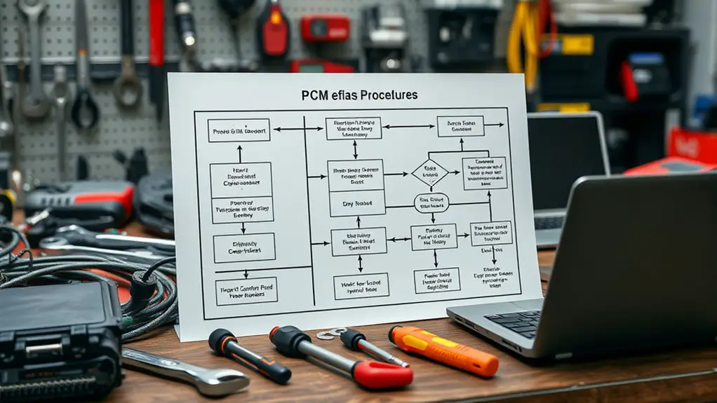
How to Build a Troubleshooting Flow for PCM Reflash Needed
You should start by evaluating whether a PCM reflash is actually needed. Build a trigger list from symptoms like erratic shifting, limp mode, parasitic drain, or unexpected resets, and verify with fault codes, live data, and readiness flags. Define clear success criteria and measurable outcomes, then collect baseline diagnostic data and confirm hardware compatibility. Prepare a controlled reflash environment, document each step, and establish robust recovery paths. If you follow this flow, you’ll set up a reliable, repeatable process for success.
Assessing When a PCM Reflash Is Required

Determining whether a PCM reflash is needed starts with a clear trigger list and a disciplined assessment. You approach this with a precise, objective mindset, listing symptoms and symptoms-driven thresholds without guesswork. Start by cataloging PCM symptoms observed during operation—erratic shifts, limp mode, parasitic drain, or unexpected resets—and note their frequency, duration, and context. Next, deploy diagnostic tools that you trust: scan for fault codes, verify live data streams, and check for readiness flags across core modules. Compare current readings with baseline maps for your vehicle’s make and model, isolating anomalies that point to firmware-level faults versus sensor or wiring issues. Establish a decision boundary: if multiple symptoms align with known reflash triggers and the diagnostic tools corroborate abnormal firmware behavior, proceed to plan a controlled reflash. Maintain documentation for traceability, keep a rollback path, and prioritize safety and reproducibility in every step.
Defining Success Criteria for Reflash Procedures
Establish clear success metrics up front, so you know what constitutes a successful reflash. Define measurable outcomes and tie them to concrete thresholds, pass/fail criteria, and timing targets. Outline validation steps to confirm the procedure meets the criteria and to flag deviations early.
Clear Success Metrics
Clear success metrics provide a precise target for PCM reflash procedures: they define what “done” looks like, how to measure it, and when to stop testing. You’ll set objective criteria that reflect reliability, safety, and repeatability, aligning with performance indicators and success benchmarks. Use clear thresholds to avoid ambiguity and guarantee consistent execution across technicians. Establish evaluation steps, data collection methods, and pass/fail criteria that translate into actionable work items.
- Define success benchmarks for functional restoration and stability
- Specify quantitative performance indicators and acceptable variance
- Set reproducibility requirements across cycles and units
- Document decision gates that trigger halt, retry, or escalation
Measurable Outcomes
Measurable outcomes define what a successful PCM reflash looks like in practice, translating broad goals into concrete, verifiable results. You’ll map each objective to specific, observable criteria, then assess progress against them with disciplined rigor. Start by pinpointing the essential performance indicators that reflect firmware integrity, system stability, and fail-safe behavior. Define acceptable thresholds for boot times, diagnostic pass rates, and post-flash validation results. Document how you’ll measure each indicator, including data sources, sampling frequency, and acceptance criteria. Use a linear, auditable chain from action to result so a reader can reproduce the test at any stage. Keep measures independent to prevent cross-influence, and prioritize early-warning signals that trigger corrective steps before escalation. These measurable outcomes enable transparent decision-making and disciplined, freedom-respecting progress.
Criteria Validation Steps
How do you determine success for a PCM reflash? You establish clear criteria, then verify them through structured steps. You’ll define objective endpoints, then confirm outcomes with repeatable checks that reflect real-world use. Your approach blends criteria assessment with disciplined validation protocols to minimize guesswork and risk. Focus on measurable thresholds, reproducibility, and traceability so every result is defensible.
- Define success metrics: functional, performance, and safety targets with concrete numbers
- Establish prove-out tests: repeatable scenarios that mirror field conditions
- Document acceptance criteria: pass/fail rules, tolerances, and rollback plans
- Validate results: independent review, cross-checks, and logs for auditability
This method honors freedom by giving you a disciplined path, not a guesswork shortcut.
Gathering Essential Diagnostic Data Before Reflash

You’ll start by identifying Critical Diagnostic Metrics that must be captured prior to any reflash and by outlining exact thresholds for triggering action. Next, follow Data Collection Protocols that specify where to gather data, in what order, and how to document timestamps and sources for traceability. Finally, perform Pre-flash System Checks to verify battery health, charging stability, and ECU communication to avoid misleading results.
Critical Diagnostic Metrics
Critical diagnostic metrics are the heartbeat of a successful PCM reflash workflow. You’ll map essential signals before you touch the flash, keeping the process clean and controllable. Focus on reproducible indicators that inform risk and timing, not whimsy. Use diagnostic tools to capture baseline behavior and performance metrics to quantify stability. The goal is a concrete read on health, not guesswork, so define thresholds upfront and verify them under load. Document every observation concisely, ensuring repeatability across sessions. Maintain discipline in data interpretation, resisting premature conclusions. This approach preserves freedom to act with confidence, avoiding blind steps.
- Baseline readings from diagnostic tools and sensors
- Key performance metrics under normal and stressed conditions
- Fault indicators and error codes with timestamps
- Reflash readiness criteria and safety gates
Data Collection Protocols
Data collection sets the foundation for a safe, repeatable reflash. You’ll gather exactly what you need, nothing more, to protect data integrity and maximize diagnostic accuracy.
| Step | Action |
|---|---|
| 1 | Capture vehicle identifiers, PCM part numbers, and firmware version. |
| 2 | Log error codes, freeze frames, and recent drivability symptoms. |
| 3 | Record tool version, connection method, and battery status. |
| 4 | Verify timing, ambient conditions, and data timestamp consistency. |
You maintain discipline: avoid speculative notes, document sources, and confirm measurements before proceeding. This disciplined protocol supports repeatability and freedom to troubleshoot boldly, without compromising data quality. When you finish, review for gaps and secure backups, ensuring data integrity remains intact and diagnostic accuracy stays high through the reflash process.
Pre-flash System Checks
Pre-flash system checks establish the baseline data needed to judge reflash results. You’ll gather objective inputs that anchor decisions, preventing guesswork later. Approach this step with a focused, repeatable routine, using clearly defined criteria and tools for consistency. Prepare to capture both hardware and software signals, noting any anomalies before you reflash. Your aim is a concise snapshot that reveals deviations and trends, not excuses.
- pre flash checklist
- diagnostic toolkits
- data capture standards
- verification criteria
This phase is about discipline, not drama. You’ll align measurements with documented tolerances, log timestamps, and verify tool compatibility. By codifying each parameter, you enable traceable results and faster troubleshooting if issues arise post-flash. Stay exact, stay deliberate, stay free to iterate within structure.
Verifying Hardware Compatibility and Firmware Baselines
Verifying hardware compatibility and firmware baselines starts with a precise inventory of your PCM’s model, revision, and current firmware level, then cross-checks these against the manufacturer’s supported configurations. You’ll verify hardware specifications, confirm physical interfaces, and map each component to the documented baselines. If deviations exist, you determine whether they’re permissible variations or indicators for an update path.
| Attribute | Action |
|---|---|
| PCM model / revision | Confirm against OEM listing |
| Current firmware | Note version, build, release date |
| Supported configurations | Compare features, interfaces, limits |
Proceed to align your findings with the official baseline. If mismatches appear, document exact discrepancies and plan firmware updates or hardware substitutions per guidance. Maintain a concise changelog for traceability. This step guarantees your reboot path isn’t blocked by noncompliant hardware specs or out-of-date firmware. You’ll use this verified baseline to drive a safe, predictable reflash flow, preserving freedom to adapt without risking compatibility gaps.
Preparing the Reflash Environment and Safety Measures
Before you begin the reflash, establish a clean, controlled workspace and gather all required tools and materials, including power protection, proper connectors, and the latest firmware package. You’ll approach this methodically, setting up a stable power source, anti-static ground, and clear ventilation. Confirm environment setup basics, like lighting and clutter-free surfaces, to minimize interference and accidental disconnects. Safety protocols demand a non-slip mat, insulated tools, and a method to interrupt power quickly if needed. Document serial numbers and firmware version checks to guarantee traceability. Maintain a focused mindset, and avoid distractions that could compromise data integrity or component health. Keep a concise log of steps and observations so you can reproduce or audit the process later.
- Prepare the work area with grounded power, clean surfaces, and organized cables
- Verify firmware package integrity and compatibility
- Align connectors and seating with precise, deliberate motion
- Record outcomes and any anomalies for follow-up verification
Selecting the Right Reflash Tools and Software Versions
To start, you should verify tool compatibility across your PCM model and reflashing interface to prevent mismatch issues. Next, implement version control strategies to track software builds and revert safely if a flash fails. Finally, outline safe reflashing procedures that cover power stability, backup plans, and recovery steps to minimize risk.
Tool Compatibility Checks
Selecting the right reflash tools and software versions is critical to a successful PCM reflash, so start by confirming compatibility between the vehicle’s ECU model, the reflash module, and the software package you plan to use. You’ll map tool specifications against your ECU requirements and verify that each component supports the intended firmware revision. Use a concise compatibility matrices approach to avoid guesswork and speed up troubleshooting. Verify all interfaces, cables, and power thresholds meet minimums, and document any deviations for later review.
- tool specifications alignment with ECU model
- software version vs. firmware requirements
- compatibility matrices for modules and interfaces
- power, communication, and safety edge cases documented
Version Control Strategies
Version control starts with aligning tools and software versiones to the ECU’s requirements; pick the reflash tool, firmware package, and diagnostic software that explicitly support the target ECU model and firmware revision. You’ll establish clear baselines, document changes, and verify compatibility before flashing. This practice reduces drift between environments and strengthens change management. Choose versioned bundles where each component lists supported revisions, and maintain a changelog for quick traceability. Schedule controlled updates, tag releases, and conduct regression checks after each modification. Use a table to compare tool versions and firmware bundles at a glance.
| Tool | Firmware | Diagnostics |
|---|---|---|
| A | v1.x | D1 |
| B | v2.x | D2 |
| C | v3.x | D3 |
Safe Reflashing Procedures
Choosing the right reflashing tools and software versions is critical to a safe procedure; start by confirming compatibility with your ECU model and current firmware, then verify that each component—reflash tool, firmware package, and diagnostic suite—explicitly supports that revision.
- Confirm ECU-specific compatibility for tool, firmware, and diagnostics
- Verify version alignment across reflash tool, firmware package, and software suite
- Review safety protocols and failure handling before starting
- Prepare verified backups and a controlled environment for execution
Follow a disciplined, stepwise workflow to minimize risk with reflash techniques, ensuring no step proceeds without explicit validation. Maintain clear rollback options and document each version used. Adhere to safety protocols at all times, and avoid improvisation. This approach preserves stability, supports recovery, and respects user autonomy while delivering precise, repeatable results.
Building a Step-by-Step Reflash Workflow
To build a step-by-step reflash workflow, start by mapping the exact sequence of actions from initial diagnostics to completion and verification. You’ll define entry criteria, required tools, and safety checks, then outline each discrete task with time estimates and owners. Design logical branches for common conditions, but keep core flow linear to minimize confusion. Establish clear handoffs between steps, and pair them with objective success criteria that trigger progression or pause. Include version control for firmware, configuration backups, and rollback points. Document data capture at every stage: logs, checksum verifications, and device responses. Build in verification steps that confirm functional criteria before moving forward. Emphasize collaboration techniques for cross-functional input and troubleshooting strategies for rapid issue isolation. Craft the workflow to be reproducible, auditable, and adaptable, so operators can scale with confidence. Finally, test the flow in controlled scenarios, refine gaps, and lock in a concise, reusable protocol.
Handling Common Failures and Recovery Paths
When a reflash encounters common failures, start with a disciplined triage to isolate root causes quickly: verify power stability, confirm proper tool and cable connections, and recheck firmware integrity before proceeding with recovery steps. You’ll target likely blockers first, then move to corrective actions with repeatable checks. This mindset minimizes guesswork and accelerates restoration.
- Confirm battery or supply voltage is steady and within spec
- Validate tool compatibility, cable integrity, and secure connectors
- Revalidate the firmware package hash and integrity before flashing
- Apply a controlled retry protocol, logging each outcome for traceability
Recovery techniques emphasize containment, repeatability, and documentation. If a fault persists, isolate the module, reflash in a clean environment, and verify post-flash indicators before broader testing. Maintain a concise audit trail, note deviations, and standardize prompts to guarantee consistent diagnostics. This approach preserves freedom by empowering you to act decisively, yet within a precise framework that reduces risk and enhances predictability. Common issues are addressed through disciplined checks, disciplined retries, and disciplined documentation.
Validating Post-Reflash Functionality and Data Integrity
Post-reflash validation should proceed from core functionality outward, starting with a quick sanity check of the system state and expected boot indicators. You verify that essential subsystems initialize without errors and that diagnostic LEDs or status codes reflect normal startup. Next, perform reflash testing focused on core interfaces: CAN, LIN, or Ethernet communications, confirming data frames are transmitted and received correctly with expected timing. Then, validate application-layer readiness by observing module availability, boot messages, and correct feature flags. Move to functionality verification of critical paths: input handling, sensor fusion, and actuator commands, validating end-to-end responses under nominal loads. Record deviations with precise timestamps and reproducible steps. Maintain a controlled test environment to distinguish genuine regressions from transient conditions. Finally, compare post-reflash data hashes and firmware metadata against baselines to verify integrity. This disciplined approach yields actionable evidence of success and highlights areas needing attention before broader deployment.
Documenting the Decision Points and Verification Results
From here, you capture the decisions that shaped the verification plan and the results that validate it. You present a concise record of decision analysis and verification methods, linking choices to measurable outcomes. Each point states the rationale, the expected impact, and how it’s tested, so the path remains transparent and repeatable. You keep the language direct, avoiding fluff, to empower engineers who crave freedom through clarity. Documentation focuses on traceability, reproducibility, and auditable checkpoints that others can follow without ambiguity. You separate decisions from results, then map them to concrete evidence and acceptance criteria. The result is a living artifact that supports iterative refinement and quick onboarding for new team members.
- Decision rationale and traceability for each verification method
- Test setup, data, and acceptance criteria aligned to goals
- Evidence and result summaries with pass/fail rationales
- Change history and rationale for future rework
Frequently Asked Questions
What if the PCM Refuses to Enter Flash Mode?
If the PCM refuses to enter flash mode, check for flash mode issues first, then verify wiring and power across the harness. Confirm ignition is stable and ground is solid, retry with a known-good USB/diagnostic tool. Use diagnostic tools to confirm voltage levels and modes, and attempt alternate entry sequences. If resistance remains, isolate the PCM and test with a spare module. Document steps, errors, and outcomes for precise, repeatable progress.
How to Back up Factory Calibration Before Reflash?
Did you know that about 1 in 4 reflash attempts include a calibration mismatch, highlighting the need for a solid backup? You back up factory calibration by following a precise method: choose reliable backup methods, connect your calibration tools, and copy the original flash data to a secure, verifiable location. Verify integrity with checksums, label versions clearly, and keep the archive organized. This disciplined approach preserves options while you work through the reflash.
Can Reflash Affect Immobilizer and Key Security?
Yes, a reflash can affect immobilizer and key security. You’ll need to verify immobilizer functionality post-flash and confirm key programming stores, transponder data, and PINs correctly. Start by scanning for fault codes, then reinitialize immobilizer and test every programmed key. Keep logs of changes and guarantee secure calibration backups. If issues arise, revert to backup calibration, reattempt immobilizer alignment, and verify all cryptographic data matches the vehicle’s original configuration. Maintain procedural discipline throughout.
What Are Rollback Steps After a Failed Flash?
If a flash fails, your first step is to halt the procedure and assess the error: initiate rollback procedures, then verify tool status. Next, engage flash recovery by restoring the prior image from a trusted backup, validating checksums, and confirming PCM boot readiness. Proceed with a controlled reflash only after confirming stable hardware signals. Document each action, keep telemetry open, and maintain a clear rollback trail to protect immobilizer integrity and guarantee freedom to troubleshoot confidently.
How to Verify Post-Flash ECU Torque/Engine Behavior?
You’ll verify post-flash ECU torque and engine behavior by validating ECU performance and running thorough engine diagnostics. Start by logging live data: RPM, acceleration, load, throttle response, and fuel trims. Compare against baseline targets, note any deviations, and confirm stability through steady-state and transient tests. Check for drivability issues, misfires, or abnormal trims. If anomalies appear, retrace steps, document changes, and re-run diagnostics until performance aligns with planned torque and engine behavior.