How to Clear False Codes and Stop Noisy CAN Bus From Returning
To clear false CAN fault codes and stop noise from returning, start with a structured fault origin check. Isolate segments, collect concrete data (voltages, timing, error counters), and verify timing, filters, and diagnostics against nominal values. Inspect wiring, terminations, grounding, and shielding; fix impedance issues and eliminate ground loops. Identify EMI sources, minimize loop areas, and guarantee shields terminate correctly. Reset fault memory per the controller’s procedure, then standardize node timing and robust bus controls—and you’ll stay ahead of issues as you continue.
Diagnosing Fault Origins on the CAN Bus
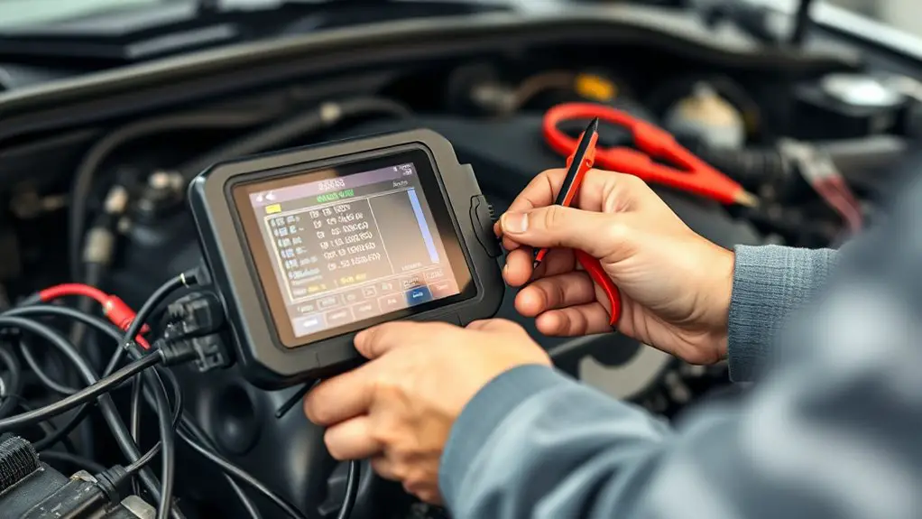
Diagnosing fault origins on the CAN bus starts with a systematic approach: identify the symptom, then trace it to its source. You’ll map observed faults to potential nodes, wires, or connectors, keeping scope tight to avoid scope creep. Begin with fault isolation techniques: segment the network mentally, test each leg, and isolate anomalies before broad assumptions form. Collect concrete data: voltages, bit-timing settings, error counters, and crash logs, then correlate with physical layer realities. Next, perform signal integrity analysis to assess bus loading, termination quality, and reflections that masquerade as faults. Inspect terminations, trunk and drop continuity, and shielding integrity, documenting deviations precisely. Prioritize reproducible scenarios, recording whether errors are intermittent or persistent. Maintain a change log for every intervention to distinguish root causes from symptoms. Throughout, stay disciplined: avoid premature conclusions, verify fixes with controlled tests, and confirm that corrected behavior persists under normal operating conditions. Your freedom hinges on disciplined diagnosis, not guesswork.
Verifying Timing, Filters, and Diagnostics
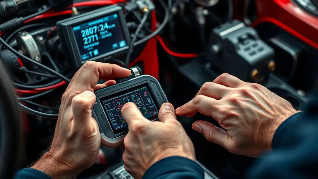
Once you’ve isolated the fault, verify timing, filter behavior, and diagnostic outputs by cross-checking the CAN clock, bit-timing parameters, and acceptance filters against the configured network specifications, then confirm that diagnostic counters and error reports reflect real conditions rather than transient noise. To do this, perform a concise timing analysis and validate filter adjustments against observed bus activity, avoiding over-interpretation of sporadic events.
Once you’ve isolated the fault, verify timing, filters, and diagnostics against network specs, ensuring measurements reflect real conditions rather than noise.
- Compare nominal baud rate and sample point to actual measurements under load
- Verify acceptance filters align with node IDs and message IDs in use
- Check error counters for persistent trends, not momentary spikes
- Correlate diagnostic reports with known faults, not fleeting chatter
- Confirm no hidden resets or clock drifts skewing timing analysis and filtering decisions
Checking Timestamps and Node Corroboration
You’ll start by checking Timestamp Alignment across the CAN network to guarantee events line up between nodes. Then perform a Node Corroboration Check to confirm that multiple nodes report the same state within the expected window. Finally, use Cross-Device Verification to compare messages from different ECUs and validate consistency before drawing conclusions about fault codes.
Timestamp Alignment
Timestamp alignment is about verifying that all nodes’ timestamps are consistent and that recorded events line up across devices. You’ll measure timestamp synchronization across ECUs and the bus to confirm simultaneous frames reflect the same moment in time. You’ll assess timestamp accuracy under load, and validate that drift stays within tolerance so later analysis remains trustworthy.
- Cross-check boot and power-on times
- Compare frame timestamps against a reference clock
- Validate clock drift stays within specified limits
- Correlate events with known external triggers
- Document any discrepancies for corrective action
Keep the process disciplined: document results, adjust firmware or hardware timing, and re-test. This clarity supports your freedom to reason about faults, reduce noise, and guarantee confident decision-making without unnecessary complexity.
Node Corroboration Check
A Node Corroboration Check verifies that a node’s timestamps align with the rest of the network and that recorded events are corroborated across ECUs. You perform a tight comparison of each message’s time tag against a consensus window, flagging drift beyond a defined margin. Focus on node identification: confirm that the sender’s identity matches expected sources and that cascading timestamps remain coherent across the bus. In signal analysis terms, you correlate event sequences, filtering out outliers caused by jitter or clock skew. When discrepancies appear, trace them to root cause rather than symptoms, documenting timing offsets and the implicated nodes. This discipline preserves reliability, sustains CAN integrity, and supports rational decisions to suppress false codes without sacrificing network responsiveness. Continuous refinement through logging reinforces freedom with accountability.
Cross-Device Verification
Cross-Device Verification builds on Node Corroboration by testing coherence across multiple ECUs and their time tags. You verify that timestamps align within tolerance and that data trends match expected inter device communication. In practice, you compare cross-node messages, confirming cross device compatibility and ruling out clock drift as a source of false codes. You’ll document discrepancies, isolate misbehaving nodes, and re-synchronize where needed. The goal is a consistent, auditable state across the network, ensuring reliability without sacrificing freedom to improvise repairs. Use deterministic checks, not guesses, to preserve performance margins.
- Timestamp alignment checks
- Cross-node message consistency
- Clock drift assessment
- Fault isolation across ECUs
- Re-synchronization procedures
Inspecting Wiring, Termination, and Grounding
Start with a concise wire integrity check to verify there are no breaks or nicks in the CAN pair. Verify proper termination at both ends, using the correct resistor values and placement, and guarantee the topology matches the network design. Confirm grounding and shielding are intact, bonded to chassis or a common ground, with shields terminated appropriately to minimize EMI pickup.
Wiring Integrity Checks
Wiring integrity checks begin with a systematic inspection of the physical layer: verify that all harnesses, connectors, and cables are intact, properly seated, and free of damage or corrosion, then confirm that termination resistors match the network’s specification and are located at the correct ends of the bus. You’ll assess wiring diagrams for the layout, trace routes, and identify potential interference paths. Prioritize signal quality by checking for clean differential pairs, shielding continuity, and consistent impedance. Document any anomalies before proceeding to tests.
- Inspect harness routing and connector seating
- Verify shield continuity and ground integrity
- Cross-check resistor values and end-placement
- Examine for corrosion, pulls, or pin misalignments
- Validate impedance and cable consistency across runs
Proper Termination Practices
Proper termination practices are fundamental to preserving signal integrity on a CAN bus. You’ll inspect wiring layouts for clean paths, avoiding sharp bends and loose connections that create opportunities for impedance changes. Start with termination resistance: confirm a single, correct resistor value at each end of the network, matching the bus impedance to minimize reflections. If you detect excessive signal reflection, reassess cable topology and connector quality, replacing damaged parts and tightening terminals. Keep stubs short, routing away from power lines and EMI sources. Use terminations only at the bus ends, not mid-chain, to prevent standing waves. Document configurations so future work preserves reliability. When in doubt, re-measure with a known-good tester to verify that the network remains free of unexpected reflections and mismatches.
Grounding and Shielding
Grounding and shielding are essential for minimizing noise and protecting CAN bus integrity; with careful inspection of wiring, termination, and grounding paths, you can suppress EMI coupling and guarantee stable communication. You’ll methodically verify ground references, minimize loop areas, and isolate noisy devices to reduce a ground loop and electromagnetic interference.
- Inspect grounding points for solid connections and low impedance
- Verify shield termination at one end only to avoid ground loops
- Separate power and signal grounds where feasible
- Route cables away from high‑current loops and sources of EMI
- Test continuity and shield integrity after reconnections
This disciplined approach keeps the network resilient, preserving freedom to move, innovate, and troubleshoot without false codes.
Identifying and Reducing Noise Sources
When addressing noise sources in a CAN bus system, start by identifying potential emitters and paths that can inject erroneous signals. You’ll map insofar as possible to the physical layer: cables, connectors, ground references, and proximity to high‑current switching devices. Catalog devices that actively drive or terminate, plus passive components that can alter impedance, creating reflections or stray coupling. Next, trace the signal paths: trunk lines, stubs, and enclosure routes where EMI can couple into CAN_H or CAN_L. For each source, assess whether its influence appears as common‑mode or differential noise and quantify potential amplitudes relative to bus voltage. Implement and validate noise filtering techniques early—carefully chosen filtering notches, time constants, and a conservative approach to debouncing. Maintain a focus on signal integrity: guarantee termination is correct, impedance matches are preserved, and grounds remain stable during operation. Your goal is a robust, resilient bus that tolerates environment variability while preserving deterministic communication.
Resetting Fault Memory After Verification
Having verified the bus integrity and ruled out persistent fault-inducing noise, you can proceed to reset the fault memory after verification. This step clears historical events without reintroducing faults, enabling clean operation and accurate future diagnostics. Follow structured reset procedures to avoid ambiguity and guarantee traceability.
- Confirm the controller supports a fault memory reset command and note applicable timestamps
- Execute the reset sequence exactly as documented, logging each step
- Verify the memory cleared indicator or readback value confirms zeroed fault memory
- Recheck CAN IDs and message timing after reset to guarantee no residual state remains
- Document the action, including tool used, firmware version, and user context for future audits
After reset, run a short verification cycle to guarantee no new faults appear. Maintain discipline: only reset after verified stability, and preserve a clear record for accountability and freedom in future troubleshooting.
Implementing Preventative Measures for Stable Communication
To guarantee stable CAN bus communication, implement preventative controls that minimize noise, timing jitter, and misalignment between nodes. You’ll adopt preventative strategies that target root causes before faults surface. Begin with disciplined node synchronization: align sampling points, configure precise bit timing, and lock the bit rate across all ECUs. Enforce robust termination and proper grounding to reduce reflections and ground loops; verify resistor values and chassis connections on every node. Next, standardize communication protocols with clear priority handling, error counters, and deterministic wake/sleep behavior to avoid surprise traffic bursts. Apply bus-off recovery rules that prevent transient faults from cascading, and maintain a shielded, organized cable layout to limit EMI susceptibility. Regularly audit firmware compatibility, ensuring updates preserve timing budgets and do not introduce protocol regressions. Finally, document change control and test across scenarios, so preventative strategies become repeatable and effective in real-world networks.
Frequently Asked Questions
How Often Should You Clear CAN Fault Memory After a Fix?
Answer: You should clear fault memory after a fix only once you’ve verified the repair holds, then recheck the system. In practice, perform a diagnostic run and monitor for a full cycle; if no new codes appear, memory reset intervals can be set to the next planned maintenance window. Keep fault code frequency logs, and document each clearance. You’ll feel empowered knowing you control the process, not the faults.
CAN Software Updates Affect CAN Bus Noise Levels?
Yes, software updates can affect CAN bus noise levels. You should expect CAN signal integrity to shift as firmware changes timing, message prioritization, and error handling. Review the software version impacts by comparing before-and-after bus activity, and test under load to confirm improvements. If issues persist, revalidate termination and didn’t ignore tolerances. Keep logs, document deviations, and rollback if necessary to preserve signal integrity while embracing improvements from the software version impacts.
Do Different CAN Protocols Influence Fault Code Persistence?
Yes, CAN protocol variations influence fault code longevity. You’ll see different protocol differences modulating how quickly faults persist to the diagnostic layer, with some standards clearing codes faster than others. Think of it like a bridge toll—if your system tolerates longer congestion, fault indicators stay active longer. Noise interference impact varies by protocol, so you’ll want to match fault handling to the chosen CAN protocol, ensuring timely, reliable fault visibility.
Is Battery Ground Isolation Needed for Noisy Environments?
Yes, you should pursue battery isolation in noisy environments. You’ll implement robust battery isolation to decouple ground noise from the CAN bus, reducing interference and false fault signaling. Start with a high-impedance, well-grounded isolation barrier and verify isolation ratings meet surge and EMI specs. Then monitor for residual chatter with differential signaling, shielded cables, and proper grounding. You’ll gain cleaner CAN communication, fewer false codes, and greater system reliability in demanding, freedom-loving setups.
CAN EMI Shields Impair CAN Bus Timing Accuracy?
Yes, EMI shields can modestly impair CAN bus timing if not designed or implemented correctly. You’ll want to assess CAN shield effectiveness in shielding EMI interference without adding impedance mismatches or excessive capacitance. Keep shield grounding solid and return paths clean, use twisted pairs, and minimize shield participation in signal lines. You’ll preserve timing accuracy by avoiding unnecessary shielding routing, testing under load, and choosing materials that balance EMI reduction with minimal signal degradation.

