How to Clear False Codes and Stop OBD Adapter Connection Failure From Returning
To clear false codes and stop recurring OBD adapter failures, start by validating adapter compatibility with your vehicle’s protocol and PIDs, then confirm ignition on and stable battery voltage. Perform calibrated fault clears using manufacturer procedures, log live sensor data, and monitor delta trends to guarantee stabilization. Clean and reseat ports, verify grounding, and reseat connectors to minimize EMI. Maintain a repeatable diagnostic routine, document steps, and watch for recurring patterns—consistency now prevents future surprises. More specifics await.
Understanding False Codes and How They Occur
False codes are incorrect fault indications generated by the OBD system or its supporting diagnostics. You’re aiming for clarity, so you’ll treat each entry as a data point rather than a narrative. False codes arise when sensors report transient conditions, wiring faults, or calibration drift that the interpretive logic misclassifies, producing a mismatch between observed signals and stored code definitions. You’ll map occurrences to root causes by reviewing sensor data, time stamps, and fault frequency. Consider environmental factors, electrical noise, and cable integrity, because these elements influence false code triggers. Maintain a disciplined diagnostic workflow: reproduce conditions if safe, isolate circuits, and verify against baseline measurements. Your emphasis on diagnostic accuracy guides decision-making, ensuring you don’t overreact to nonpersistent or non-reproducible signals. Document every step, quantify confidence intervals, and cross-check with vehicle service information. With this approach, you minimize unnecessary repairs while sustaining reliable fault detection.
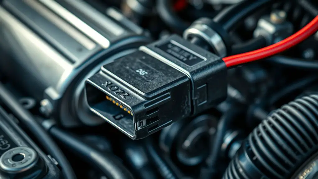
Verifying OBD Adapter Compatibility With Your Vehicle
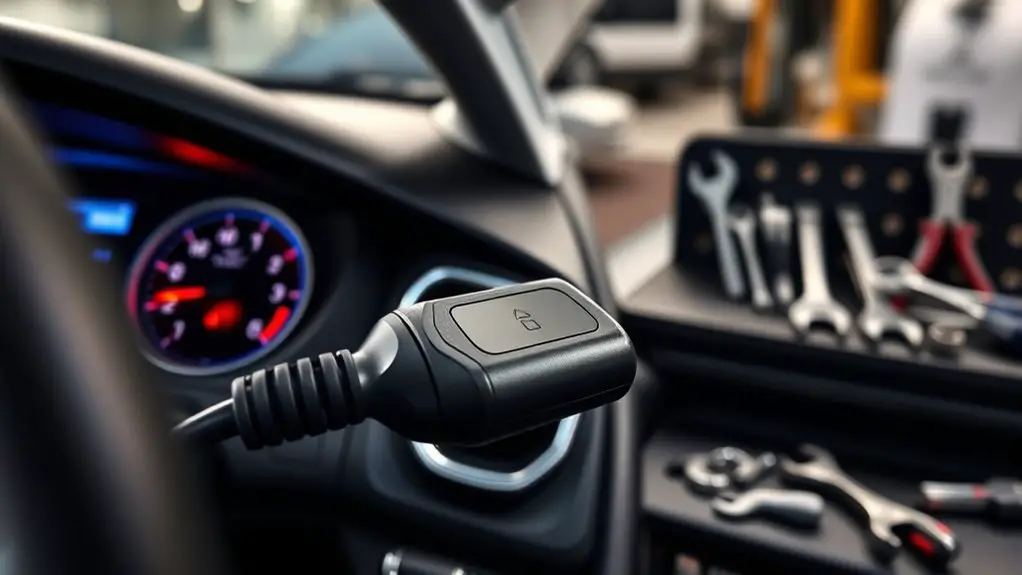
To verify that an OBD adapter will work with your vehicle, start by confirming both the connector standard and the vehicle’s data protocol. You’ll perform OBD compatibility testing by cross-referencing adapter specifications with your vehicle’s model specifications, then validate supported PIDs, baud rate, and protocol compatibility. Gather your vehicle’s model year, engine type, and ECU family as baseline data. Check OEM documentation or manufacturer databases for the exact protocol set (for example, ISO 15765-4 CAN, ISO 9141-2, or J1850). Ascertain the adapter lists those protocols and the correct connector type (J1962 for OBD-II). Test fundamental functions first: read readiness, VIN, and load values under known conditions. Document any deviations and repeat with a representative data set. If a mismatch appears, document it and seek an alternative adapter that explicitly supports your vehicle model specifications. This disciplined approach minimizes guesswork and supports reliable diagnostics.
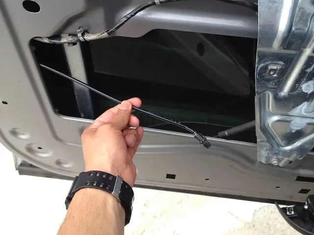
Ensuring Proper Power and Connection for Stable Readings
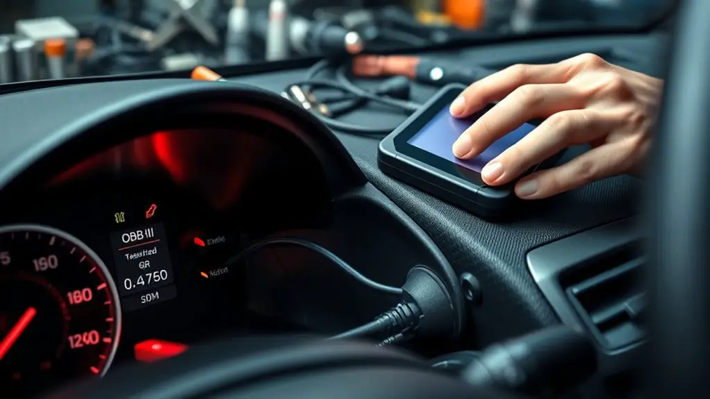
Ensuring the device is powered correctly and retained a solid connection is essential for stable readings; start by confirming the vehicle’s power state and the adapter’s power requirements before establishing the data link. You’ll verify that the ignition is on, battery voltage is within spec, and the OBD adapter shows proper bus activity. Next, confirm the power supply characteristics: voltage range, current draw, and any required supply stability or filtering to prevent dips during diagnostic bursts. Maintain a clean, dedicated power path, avoiding parasitic loads that could trigger resets. Check connection integrity at the OBD port, the adapter’s micro-USB/USB-C or Bluetooth power behavior, and any LED indicators that signal healthy link status. Secure mounts and cables to minimize movement-induced interruptions. Document observed voltages and device responses for reproducibility. When power delivery is stable and the link remains intact, you’ll enjoy reliable, repeatable readings and reduced false codes from transient power events.
Resetting Sensors and Clearing Fault Codes Safely
Once you’ve stabilized power and link integrity, you can safely reset sensors and clear fault codes by following a disciplined, data-driven procedure. You approach resets with repeatable steps, not guesswork. Begin with a controlled base state: log current sensor readings, record coolant, intake, and exhaust parameters, then document fault code interpretation from the scanner. Initiate a defined calibration cycle for each sensor marked faulty, using manufacturer-approved procedures and stable load conditions. After calibration, perform a targeted fault clears batch, verifying each cleared code against ongoing live data to confirm persistence or resolution. Use timestamped checksums to validate data integrity during resets. Maintain a delta-trend chart to verify stabilization post-calibration within specified tolerances. If a code reappears, revalidate wiring, grounding, and connector integrity before reinitializing, avoiding second-guessing. This method preserves sensor calibration accuracy and guarantees fault code interpretation remains consistent, enabling reliable, long-term operation and rapid fault resolution.
Updating Firmware and Software for Your OBD Device
Firmware and software updates on your OBD device must be approached with the same precision as calibration work. You’ll perform firmware updates only from trusted sources, verifying checksums and official release notes before proceeding. Document current version, hardware UUID, and serial data to establish a baseline for rollback if needed. Enable automatic backups, then initiate a staged update, monitoring progress in real time to detect anomalies early. Post-update, run a linted regression check: test ignition-on sequence, basic data requests, and stable PID polling to confirm compatibility with your vehicle profile. For software maintenance, apply incremental patches rather than full-image swaps when possible, reducing risk and downtime. Track version strings, feature flags, and known issues in a changelog accessible to your team. If a failure occurs, isolate the unit, restore from the latest golden backup, and revalidate sensor and adapter handshake integrity after the reset. Maintain rigorous, data-driven documentation to support ongoing freedom through reliable connectivity.
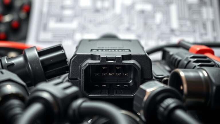
Cleaning Ports and Securing Reliable Data Transmission
You should inspect and clean port surfaces to remove oxide and debris that can cause intermittent contacts. Confirm data links are secure by verifying connector seating, applying appropriate shielding, and testing continuity with diagnostic tools. Monitor for any connection drops and document results to guide preventive maintenance and data integrity.
Clean Port Surfaces
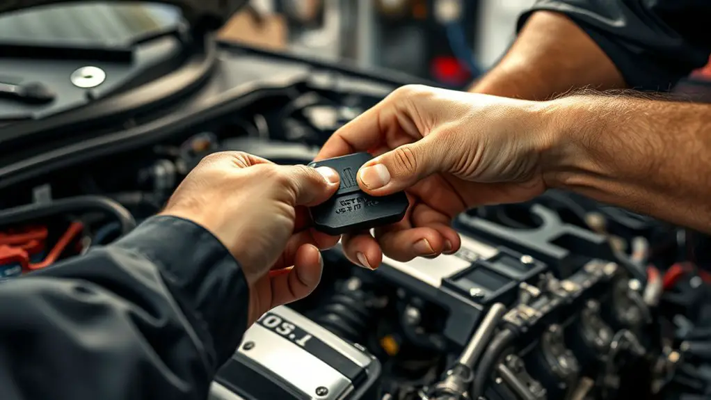
Clean port surfaces are essential for reliable data transmission between the OBD adapter and the vehicle’s ECU. You approach port maintenance with a precise workflow: inspect for corrosion, residue, and loose pins; verify connector integrity before cleaning. Use a lint-free cloth lightly dampened with isopropyl alcohol (90%+). Avoid dripping fluids and allow surfaces to dry completely. Targeted surface cleaning removes oils, dust, and oxidation without abrading contacts. Maintain consistent pressure, move in straight strokes, and rotate the connector to expose all faces. After drying, recheck pin alignment and seating to confirm a secure interface. Document results and any irregularities. This disciplined practice minimizes transmission errors, supports stable diagnostics, and upholds data integrity during live testing. Remember: port maintenance reduces false readings and enhances reliability.
Secure Data Links
To guarantee stable data transmission, begin by verifying port cleanliness and connector integrity, since secure links depend on unobstructed, low-impedance paths. You’ll implement a disciplined approach: inspect pins for corrosion, reseat adapters firmly, and confirm no bent contacts. Next, enforce secure data protocols by selecting standards that support integrity checks, retry logic, and error correction, then document handshakes and session IDs for traceability. Maintain encrypted connections end-to-end, using authenticated encryption where possible to prevent interception and tampering. Avoid loose cables or adapters that introduce impedance variance; replace worn cables promptly. Validate data throughput with baseline measurements, logging latency and packet loss. This methodical discipline yields consistent performance, supports rapid troubleshooting, and aligns with a freedom-forward mindset focused on reliable, verifiable connectivity.
Prevent Connection Drops
Begin with a disciplined check of ports and connectors: guarantee cleanliness, inspect for corrosion, and reseat every interface to establish a low-impedance, high-reliability path before data transmission resumes. You’ll prevent connection drops by enforcing a clean, repeatable surface for electrical contact, minimizing differential noise and contact resistance that disrupts data streams. Focus on connection stability through proper mating force, correct pin alignment, and verified seating depth. Apply protective measures: inspect shielding, secure grounds, and manage cable routing to reduce EMI susceptibility. For data integrity, run a baseline integrity test after reassembly, log transmission errors, and monitor latency spikes. Document findings, swap suspect components, and confirm stable handoffs under load. Freedom comes from predictable, verifiable connections that sustain uninterrupted communication.
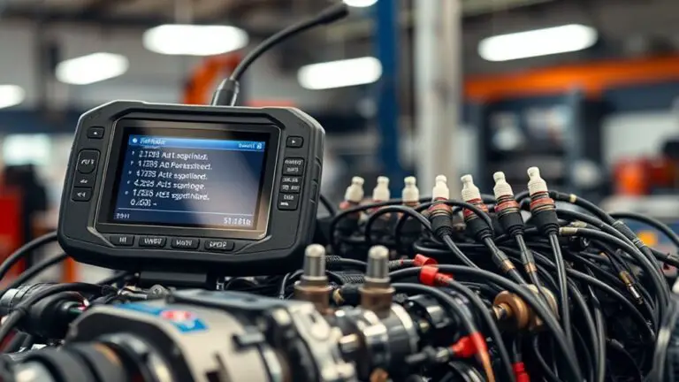
Implementing a Systematic Scan Routine to Prevent Recurrences
A structured scan protocol establishes repeatable steps that you can measure and verify, reducing variability in readings. By implementing recurrence prevention steps, you create checkpoints that catch anomalies before they propagate. Maintain diagnostic hygiene practices to guarantee data integrity and consistent results across sessions.
Structured Scan Protocols
Structured scan protocols establish a repeatable diagnostic workflow that isolates the root causes of false codes and connection failures. You implement a disciplined sequence, logging each step and outcome to verify causality. This approach yields measurable improvements: reduced repeat codes, faster fault confirmation, and clearer trend data for future sessions. Your focus is on structured scan techniques, emphasizing repeatable tests, controlled variables, and objective criteria for success. By codifying procedures, you gain portability across vehicles and adapters, preserving data integrity and reproducibility. The table below highlights key elements of the protocol, aligning actions with expected results.
| Step | Outcome |
|---|---|
| Baseline data capture | Establishes reference points |
| Targeted tests | Confirms specific failures |
Recurrence Prevention Steps
To prevent recurrences, adopt a disciplined scan routine that codifies every step from data capture to verification, ensuring repeatable results across sessions and vehicles. You’ll identify recurrence triggers, log them, and apply preventive measures with traceable outcomes, so patterns don’t reappear. Precision in data capture eliminates ambiguity, while systematic verification confirms fix integrity before moving on. Maintain a lean, repeatable workflow that scales from one car to fleet-wide use, and document each decision to support auditability and confidence. Your goal is consistent results, reduced false positives, and faster reset cycles, with a clear path from symptom to validation.
- Clear trigger tracking fuels actionable preventive measures
- Documentation cadence creates trust and repeatability
- Validation gates prevent regression and foster freedom to optimize
Diagnostic Hygiene Practices
Diagnostic hygiene hinges on a disciplined, repeatable scan routine that minimizes ambiguity and flags anomalies early. You implement a systematic plan: baseline data, consistent scanning cadence, and documented results. Use targeted diagnostic tools to validate codes, verify sensor data, and confirm idle stability. Maintain rigorous vehicle maintenance records to track wear patterns and correlate with codes. This discipline reduces false positives and prevents recurrence of adapter failures.
| Step | Action | Metrics |
|---|---|---|
| 1 | Capture baseline scans | Repeatable under similar conditions |
| 2 | Reconcile codes with live data | Cross-check with sensor trends |
| 3 | Schedule follow-up checks | Timely detection of drift |
| 4 | Log maintenance events | Correlate with diagnostics |
| 5 | Review tool calibration | Guarantee accuracy over time |
Troubleshooting Common Connection Failures and Persistent Errors
Common connection failures often come down to a few repeatable causes: incomplete pairing, unstable USB/BT adapters, or conflicting software settings. You’ll apply OBD troubleshooting techniques by isolating each factor, measuring outcomes, and documenting results. Start with a controlled test: verify device IDs, baud rates, and polling intervals; confirm that the host and adapter share a single clear session. If errors persist, examine power supply integrity and cable health, since marginal voltage can trigger connection error causes. Collect telemetry across multiple runs to distinguish transient from persistent faults, then reset to baseline and re-test. This data-driven approach helps you predict failure modes and prevent recurring issues, aligning with a freedom-forward mindset that values reliability.
- Frustration spikes when a single variable shifts mid-test; fix it and regain momentum.
- Unreliable hardware creates false confidence; swap it out and revalidate.
- Hidden software conflicts quietly undermine you; catalog and disable them systematically.
Frequently Asked Questions
Can False Codes Linger After Clearing the Fault Memory?
False codes can linger after clearing the fault memory. You’ll see residual indicators if the ECU stores freeze-frame or pending data, or if a fault reappears due to ongoing issues. Use precise clearing techniques, including rechecking readiness monitors and performing a full system retest. Persistent false codes often reflect data-drive staleness rather than a genuine fault. Review sensor ranges, voltage integrity, and wiring. If persistence continues, reinitialize the scanner and revalidate with fresh data.
Will an OBD Adapter Work With All Vehicle Models?
An OBD adapter won’t work with every vehicle model. You’ll encounter OBD compatibility issues due to Vehicle model variations, so verify compatibility first. You should check your vehicle’s year, make, and ECU protocol, then confirm the adapter supports it. If mismatches appear, you’ll need a model-specific or programmable tool. You’ll gain reliability by testing on a known compatible vehicle first and documenting any data patterns for future reference.
How Often Should I Run a Full Diagnostic Scan?
You should run a full diagnostic scan every vehicle service interval, or at least monthly for ongoing use. Diagnostic frequency depends on exposure to harsh conditions, new fault codes, or after repairs. The scan importance lies in catching mounting issues early, validating repairs, and preserving data integrity. You’ll want a methodical, data-driven approach, logging results and trends to inform maintenance decisions, while maintaining freedom to explore performance without unnecessary interruptions.
Do Low-Quality Cables Affect Data Integrity?
Low-quality cables can degrade data integrity, so yes, they do affect data transmission. In fact, studies show a significant portion of transmission errors stem from inexpensive connectors and thin insulation. You’ll notice increased retry rates and corrupted packets with poorer cable quality. To maintain precise data transmission, choose properly rated, shielded cables, secure terminations, and test continuity. Your setup benefits from consistent impedance, reduced noise, and reliable OBD data flow, supporting freedom with confidence.
Can Vehicle ECU Resets Recreate False Codes Later?
Yes, vehicle ECU resets can recreate false codes later. After a reset, the ECU’s memory clears, but sensor baselines and learned maps reset too, potentially triggering new code generation as the system relearns. You should verify ECU malfunction flags, perform controlled startup diagnostics, and recheck sensor health. Document results, avoid rushing cycles, and confirm stable operation before driving. This data-driven approach minimizes false positives and supports dependable revirtualization of the fault state.