How to Interpret ATF Pump Results for Vacuum Pump for Fluid Change
When you interpret ATF pump results for a vacuum pump during a fluid change, first establish a clear baseline of pressure, flow, and noise under normal conditions, then compare every reading against it. Track trends over time, noting ramps, plateaus, and jumps that may signal leaks or calibration drift. Correlate pressure and flow with pump speed, filter load, and reservoir level, and watch for degraded fluid effects like viscosity changes or particulates. If issues persist, you’ll uncover actionable steps ahead. You’ll find more details below.
Reading Pressure Readings During ATF Pumping
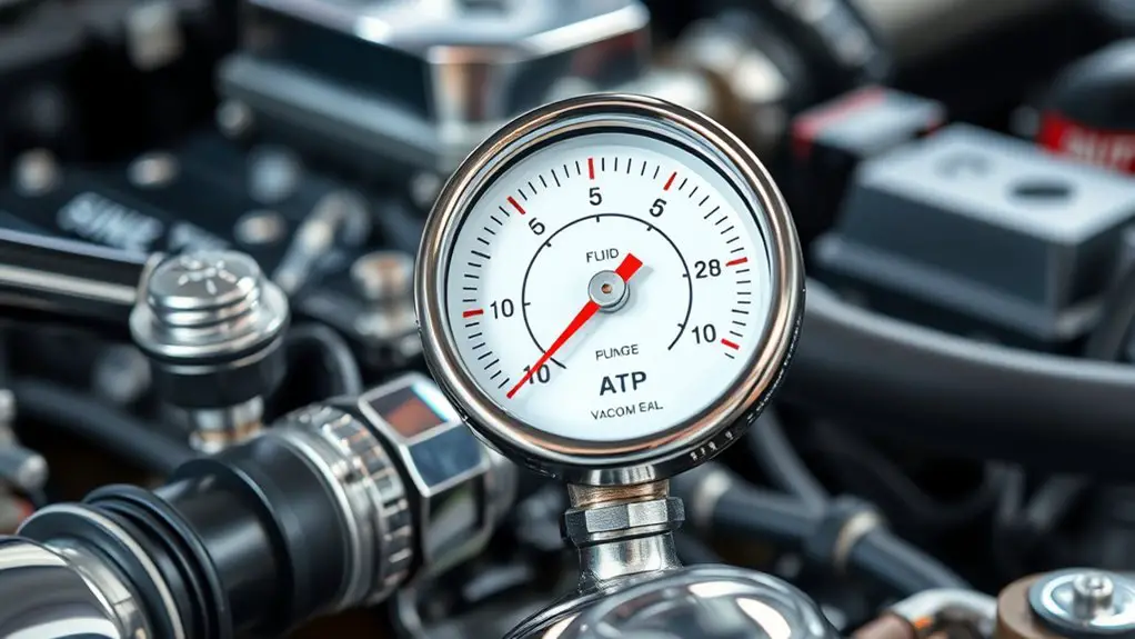
When you’re reading pressure readings during ATF pumping, focus on how the numbers change over time rather than isolated values. You’ll trace trends, not snapshots, and that discipline reveals system behavior with clarity. Start by noting baseline pressure, then watch for steady ramps or plateaus that indicate airflow changes or seal integrity. Use pressure calibration as your compass: small, consistent shifts can signal a calibration drift or measurement lag, while abrupt jumps may point to transient leaks or pump cycling effects. Evaluate pump efficiency by comparing actual pressure rise against expected performance for your configured flow rate and viscosity. If readings lag behind your model’s predictions, recheck fittings, gauge placement, and the one-way valves. Document time stamps, pressure units, and ambient conditions to support reproducibility. Your aim is a reproducible, linear interpretation toolkit that supports rapid decision-making while preserving system safety and operational freedom.
Identifying Noise Patterns and What They Signal
Noise in the readings isn’t a failure in your method—it’s information. When you identify patterns, you separate signal from noise and sharpen conclusions about the pump’s behavior. Start by cataloging recurring fluctuations: do they align with duty cycle changes, valve actuation, or ambient conditions? Such patterns point to noise sources you can isolate or account for in the data set. Next, compare successive runs under controlled variations to see if perturbations repeat or drift, which informs diagnostic techniques you can trust. Pay attention to frequency, amplitude, and timing relationships between pressure and flow indicators; abrupt spikes often signal transient events, while low-amplitude jitter may be acceptable baseline noise. Document anomalies with context—equipment state, oil level, and environmental factors—to distinguish systemic issues from fleeting deviations. Use targeted tests to confirm suspicions, then adjust procedures or filters accordingly, keeping your interpretation objective, reproducible, and aligned with your freedom to refine methods.
Assessing Flow Consistency Throughout the Process
To start, you should run Flow Consistency Checks at key milestones to verify the process stays within defined limits. Use Process Stability Metrics to quantify variance over time and flag deviations early. This sets a clear basis for comparing measurements and maintaining reliable ATF pump results.
Flow Consistency Checks
Flow consistency checks guarantee you verify that each stage of the ATF pump process delivers the expected flow rate and volume within specified tolerances. You’ll monitor gauges, watch for steady valves, and log readings at defined intervals to detect deviations early. Focus on flow variations and how they relate to pump speed, filter load, and reservoir level, then assess whether any change aligns with your targets. If a variation emerges, halt briefly, document timing, and compare against baseline profiles. Look for flow interruptions that could indicate occlusion, air ingress, or valve sticking, and trace the cause without overreacting. Maintain a concise audit trail, recalibrate if needed, and move forward with adjusted parameters only after confirming stability across subsequent checks.
Process Stability Metrics
Process stability metrics gauge how consistently the ATF pump maintains flow characteristics across the entire process, not just at individual checkpoints. You measure variation, identify drift, and quantify how small changes affect downstream performance. By tracking steadiness, you’ll align operations with process optimization goals and reduce surprises during fluid change.
- A steady cadence across stages, like a drumbeat, minimizes turbulence and guarantees predictable suction and discharge.
- Real-time gauges highlight deviations, enabling rapid corrections before they compound.
- Consistent flow yields reliable benchmark data, supporting performance benchmarking and transparent comparisons over time.
Keep the focus on consistency, not complexity; clarity drives freedom. Use standardized metrics, document deviations, and compare runs to reveal true efficiency gains and resilience in your system.
Interpreting Pressure Spikes and Drops
Pressure spikes and drops can reveal how the system responds to changes in demand or container conditions, so start by distinguishing transient from sustained events. You’ll track whether a spike or drop recurs with identical scenarios, or if it settles quickly. Transients hint at momentary flow shifts; sustained changes point to a new equilibrium. Look for pressure fluctuation causes and spike drop correlations across cycles to identify patterns. If spikes align with opening or closing valves, the cause is flow discontinuity; if drops follow valve closure, it’s a stoppage effect. Record durations, amplitudes, and recovery times to quantify behavior.
| Scenario | Observation |
|---|---|
| Demand surge | Spike magnitude, recovery time |
| Valve action | Drop timing, settling level |
| Leak indication | Prolonged deviation, reproducibility |
This methodical approach helps you decide on next steps without overreaching into pump health, keeping the analysis focused on pressure dynamics and freedom to iterate.
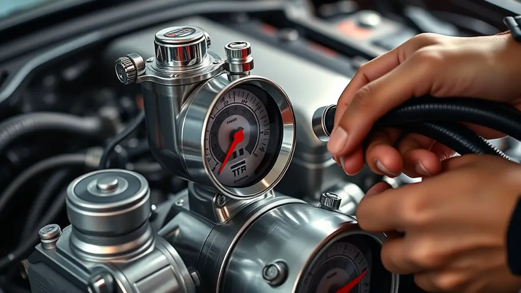
Evaluating Vacuum Pump Health Indicators
To assess vacuum pump health, focus on Vacuum Pump Health Metrics and Interpreting Vacuum Readouts to establish a baseline and detect deviations. Watch for common Fault Indicators to Watch, using systematic checks of pressure stability, vibration, and temperature alongside readouts. This approach sets the stage for targeted diagnostics and timely maintenance decisions.
Vacuum Pump Health Metrics
Vacuum pump health metrics provide a concise snapshot of performance and reliability. You’ll assess the indicators that reflect how well the pump sustains performance under load, echoes of wear, and readiness for service. Focus on steady baselines, minimal fluctuation, and reproducible results that support informed decisions about maintenance and lifecycle.
- Stable intake pressure versus target performance benchmarks
- Consistent vacuum retention with minimal leaks or outgassing
- Durable run-time without overheating or abnormal noise
These cues guide your vacuum pump maintenance, helping you separate normal variation from emerging issues. Approach each metric analytically, documenting deviations and correlating them with service intervals. By tracking a lean set of health signals, you gain freedom through predictability, reduce downtime, and sharpen your decision support for fluid-change procedures and timing.
Interpreting Vacuum Readouts
Ever wonder how readouts translate to real health? You’ll translate numbers into meaning by tracking steady baselines, short-term spikes, and drift over time. A clean vacuum readouts analysis hinges on consistent pressure at the pump inlet and a stable outlet signal during a known fluid-change cycle. Look for minor, regular oscillations that align with the pump’s operating pattern rather than random jitter. Large, rapid fluctuations often signal leaks, valve sticking, or inconsistent seals. Document the duration of any dropouts and correlate them with the cycle timeline. Pressure fluctuations interpretation becomes a diagnostic lens: gradual declines suggest wear; abrupt shifts point to component faults. Keep measurements synchronized with the test sequence, and question anomalies that don’t align with expected pump behavior or environmental conditions.
Fault Indicators to Watch
In evaluating vacuum pump health indicators, look for fault signals that consistently diverge from baseline patterns: persistent pressure drift, unexpected spikes, or prolonged dropouts tied to specific phases of the test cycle.
- Irregular pressure trends that break expected decay curves
- Sudden, non-recovering spikes aligned with cycle shifts
- Extended pauses in readings during critical test windows
These fault indicators guide fault identification techniques and reveal underlying pump performance indicators. If you detect these patterns, tighten monitoring, compare against established baselines, and document deviations promptly. Maintain a disciplined approach: verify sensor integrity, rule out ambient fluctuations, and re-run cycles to confirm persistence. The goal is to distinguish transient noise from meaningful signals, ensuring you act only on reproducible anomalies that impact reliability and fluid-change outcomes.
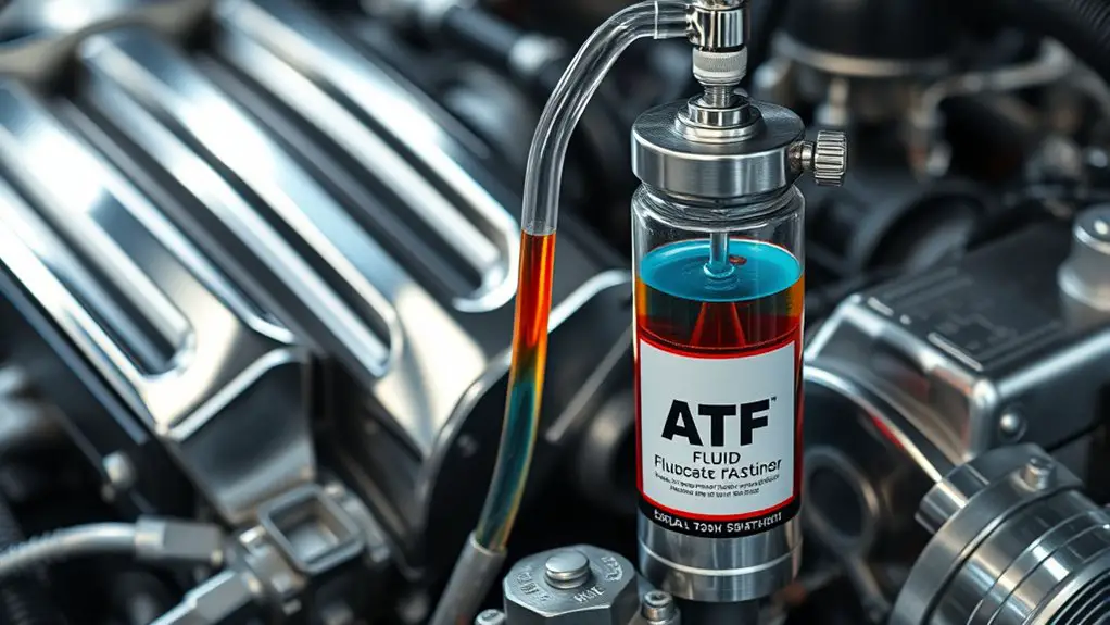
Linking Fluid Quality to Pump Performance
Fluid quality directly influences pump performance, and understanding this link helps diagnose issues faster. You’ll see how fluid degradation alters viscosity, contaminant load, and foaming tendencies, all of which shape flow and seal efficiency. When degradation progresses, you experience increased resistance, slower response times, and erratic pressure readings, signaling a clear performance correlation between fluid state and pump behavior. You’ll want to track viscosity shifts, particulate content, and thermal stability, because each factor feeds back into seal wear and bearing load. A clean, stable fluid supports consistent vacuum levels, while degraded fluid introduces micro-abrasives and dissolved acids that degrade surfaces and alter lubrication. By focusing on measurable changes rather than assumptions, you create a reliable diagnostic framework: identify anomalies, correlate them with known degradation patterns, and adjust your analysis accordingly. This disciplined approach lets you predict performance issues before they escalate, preserving efficiency and extending pump life.
Practical Checks to Perform Before and After Fluid Change
Before you change the fluid, perform a quick baseline check to establish a reference point for comparison; this helps you spot deviations after the change. You’ll want a methodical plan that reinforces fluid level tracking and pump maintenance discipline. Record initial readings, listen for unusual sounds, and verify seals and connections are dry and intact. Then perform the change, and recheck to confirm consistency with expectations.
- Baseline measurements of fluid level and pressure
- Inspect seals, hoses, and fittings for wear or leaks
- Reassess pump noise, vibration, and overall temperature after replacement
Post-change checks should focus on stability: confirm the fluid level is correct, monitor for gradual changes, and compare against your baseline. If discrepancies appear, review your valve positions, cleanliness of the reservoir, and any residual contamination. Maintain a concise log to support future comparisons. This routine reinforces fluid level awareness and pump maintenance, helping you sustain performance without overhauling the system. Stay precise, deliberate, and committed to ongoing, data-driven checks.
Common Reading Pitfalls and How to Avoid Them
Common reading pitfalls often trip up even seasoned practitioners, but you can sidestep them with a disciplined approach. You’ll examine readings as data points, not verdicts, recognizing that single numbers rarely tell the full story. Start with baseline context: pump model, fluid type, and ambient conditions frame what counts as normal. Watch for inconsistent units, scaling, or misread gauges, and verify against a stable reference prior to interpretation. Be alert to drift over time, multiple measurement modes, and the influence of transient fluctuations during operation. Document every step to avoid misinterpretations stemming from memory gaps. When results look odd, separate symptom from cause by cross-checking with corroborating indicators (pressure trends, flow rate, end-point behavior). Prioritize repeatability over impression; if a result isn’t reproducible, question its validity rather than infer meaning. By controlling methodology, you reduce common reading errors and sharpen your ability to interpret outcomes reliably.
When to Service, Recalibrate, or Replace the Pump
If you notice performance drift, rising wear indicators, or escalating maintenance intervals, you should evaluate whether service, recalibration, or replacement is warranted. You’re weighing reliability against cost, downtime, and precision. Treat each metric as a signal, not a verdict, and document the trend before acting. Recalibration is often cheaper than a full replacement when drift remains within tolerance bands, but avoid chasing precision if fundamental wear dominates.
- notice a creeping delay in response or a drop in vacuum integrity, consider recalibration first
- see persistent, growing wear indicators that don’t normalize after adjustment, plan replacement signs
- observe consistently shrinking service intervals paired with elevated monitoring effort, prepare for a replacement decision
When deciding, prioritize the maintenance plan that preserves accuracy without unnecessary downtime. If performance can’t be stabilized within defined service intervals, or replacement signs appear, opt for replacement to restore reliability and avoid underperforming changes.
Frequently Asked Questions
How Do Ambient Conditions Affect ATF Pump Pressure Readings?
Ambient conditions matter: higher ambient temperature lowers air density, while greater pressure altitude reduces ambient pressure, both altering ATF pump readings. You’ll see slightly higher pump pressure at cool, low-altitude environments and lower readings up high or in heat. To interpret accurately, normalize readings for ambient pressure and temperature, or compare to a calibrated baseline under the same conditions. You deserve precise, reproducible results, so record ambient temperature and altitude alongside each measurement.
Can Pump Noise Indicate Subtle Internal Wear Unseen in Readings?
Noise can hint at subtle internal wear that readings alone might miss. If you hear irregular clanks, thumps, or grinding, assess beyond numbers and examine pump maintenance history, seal integrity, and bearing wear. Use a methodical checklist: isolate components, compare to baseline, and log deviations. Internal wear may not show yet in tests, so inspect regularly. Prioritize proactive maintenance, replace worn parts, and track trends to prevent failures.
What Short-Term Fluctuations Are Acceptable During a Fluid Change?
Unfortunately, short-term fluctuations during a fluid change can be acceptable if they stay within specified limits. You should monitor pressure stability and pump flow, noting minor blips but avoiding abrupt spikes. You’ll want to document transient dips and recoveries, treating them as signals rather than problems. In practice, acceptable fluctuations reflect system tolerances; if readings remain within design ranges, proceed. You’re free to question anomalies, but stay methodical and decisive about fluid change progress.
Do Different ATF Brands Alter Expected Vacuum Pump Behavior?
Yes, different ATF brands can alter expected vacuum pump behavior. You should compare Brand viscosity and Fluid compatibility across options, then test your system under controlled conditions. Start with a baseline reading, then swap to a different brand and note changes in vacuum stability, draw rate, and bleed-off. Track temperature effects, check for seals compatibility, and log results. Your freedom to choose hinges on repeatable, methodical measurements that highlight practical differences in performance.
How Should Readings Be Documented for Warranty Claims?
In 87% of claims, clear data beats vague notes. You should document readings with date, time, pump model, ATF type, vacuum measured, ambient conditions, and any test sequence. For warranty documentation, record baseline and pass/fail thresholds, then attach calibration data and photos. Follow the claim process step-by-step, noting who performed the test and their credentials. Keep entries concise, objective, and reproducible to support your warranty claim.