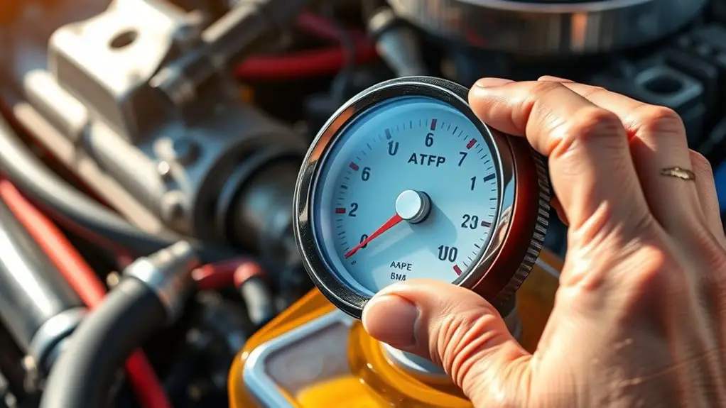
How to Interpret ATF Pump Results for Power Steering Fluid
To interpret ATF pump results, you compare flow rate and volume against manufacturers’ baselines to gauge efficiency, plus pressure readings to judge steering responsiveness. Watch for consistent flow with speed changes and stable pressures; spikes or drops signal hose leaks, worn seals, or cavitation. Note temperature trends, as high ATF temps can mask flow issues. Abnormal noise or vibration often points to wear or cavitation. If trends drift, plan a targeted service plan as suggested here to learn more.
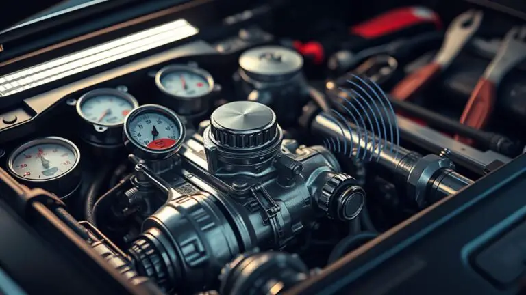
Understanding ATF Pump Basics for Power Steering
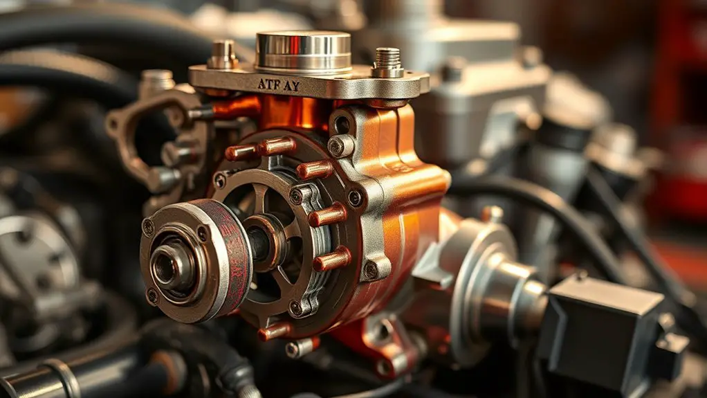
ATF (automatic transmission fluid) pumps are compact, high-pressure devices integral to power steering systems. You approach their basics with a clear, methodical mindset: identify the pump’s role, how it converts mechanical input into hydraulic pressure, and the way this pressure circulates fluid to assist steering. In operation, you observe the rotor or gears, seals, and relief valve coordinating to maintain steady flow without overheating or cavitation. You assess pump operation by tracing the path from drive shaft to pressure port, noting how clearances and wear influence efficiency. Fluid viscosity matters profoundly: too thick slows response and raises load; too thin causes timing drift and insufficient lubrication. Your analysis centers on maintaining ideal viscosity at operating temperatures to guarantee predictable response, minimal noise, and reliable steering feel. You document performance with precise measurements, correlating pump behavior to system demands while preserving freedom to refine maintenance practices.
Key Measurements: Flow Rate and Volume
You’ll start by examining flow rate basics to determine how quickly ATF moves through the pump under test conditions. Next, you’ll verify volume measurement tips to ascertain cumulative output matches the expected displacement over a defined interval. Together, these metrics establish a precise baseline for interpreting pump performance without extraneous detail.
Flow Rate Basics
Flow rate is a measure of how much fluid passes a point in a given time, typically expressed in units like liters per minute or milliliters per second. You’ll gauge performance by matching flow rate to design specs and observing how it reflects pump efficiency. Precise measurement under steady conditions reveals consistency and potential issues before they escalate.
- Understand baseline: compare observed flow rate to manufacturer targets to judge pump efficiency.
- Note variability: small deviations indicate acceptable tolerance or emerging wear.
- Calibrate tools: verify sensors and meters are zeroed and referenced correctly.
- Interpret trends: rising or falling flow rate over cycles signals hydraulic or mechanical changes impacting performance.
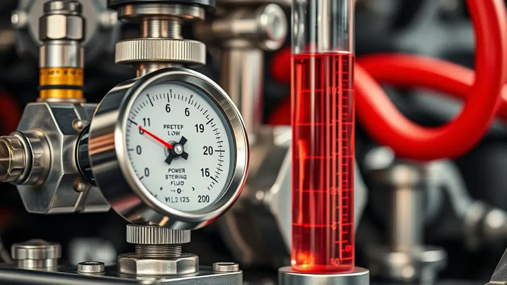
Volume Measurement Tips
Volume measurement is essential for validating both flow rate and total throughput, since accurate volume data confirm that delivered fluid matches design assumptions and system timing. You’ll use precise measurement tools to capture cumulative volume over a defined interval, aligning pump stroke counts with container marks or calibrated meters. Monitor fluid viscosity effects, since higher viscosity can bias volume readings if seals or hoses compress or stretch under load. Record temperature alongside viscosity, because ATF properties shift with heat and influence volume flow. Employ repeatable procedures: precondition fluid, purge air, and seal connections before each run. Document start and end volumes, time, and pump speed, then compute average throughput. By maintaining consistent instrumentation and clear methodology, you preserve analytical freedom while ensuring data integrity.
Pressure Readings: What They Mean for Steering Performance
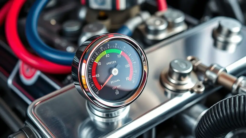
Pressure readings directly influence your assessment of steering system responsiveness, since pump pressure sets the force available to overcome hydraulic resistance. You’ll correlate pressure targets with observed steering assistance to gauge where performance may lag or exceed design expectations. This discussion centers on pressure implications and the resulting steering performance impact, establishing a basis for targeted diagnostics.
Pressure Implications
Effective pressure readings are a direct indicator of steering system performance, since they reflect how the pump, hoses, and components handle load across different operating conditions.
You’ll map how pressure fluctuations reveal internal losses and dynamic responses. By tracking peak pressures, you identify pressure loss sources and assess overall fluid dynamics, not just static values. Interpreting these readings helps you predict steering feel, response time, and potential wear.
- Identify sudden pressure drops during turns to locate hose or seal constraints.
- Compare rise times to pump priming and circuit inertia for responsiveness.
- Correlate high-velocity events with fluid dynamics-induced noise or cavitation risk.
- Benchmark against baseline readings to flag performance drift.
Focus on consistency, isolate irregular patterns, and document conditions to guide maintenance decisions.
Steering Performance Impact
When you monitor pressure readings, you’re directly evaluating how steering effort translates into motion. Readings reflect how quickly the system responds to input, not just peak values. Lower, stable pressures imply smooth steering with consistent hydraulic aid, while spikes indicate transient load or fluid behavior limits. Steering responsiveness depends on viscosity and pump delivery, so you’ll assess whether the fluid supports rapid correction without lag. If pressure lag or hysteresis appears, check for viscosity changes or worn components. Maintain consistent fluid viscosity to preserve predictable steering effort across speeds.
| Factor | Effect on Performance |
|---|---|
| Fluid viscosity | Governs response consistency |
| Pressure stability | Indicates steady steering feel |
Analyzing Pump Noise and Vibration
Analyzing pump noise and vibration requires a methodical approach to distinguish normal operation from anomalies. You’ll quantify signals, compare against baseline, and target root causes without guesswork. Focus on identifying persistent, repeatable patterns that indicate mechanical or hydraulic issues rather than transient sounds.
- pump resonance, frequency mapping, and how mounting affects amplitude
- separating noise frequency from background noise using spectral analysis
- correlating vibration signatures with pump speed and fluid temperature
- documenting thresholds that trigger further inspection or testing
Aim for concise notes: record exact RPM, ATF temperature, and any coupling or pulley changes. Listen for tonal shifts or flutter that persist beyond brief transients, and note whether sounds worsen under steering load. Use controlled tests to reproduce conditions safely, then log results with times and environmental factors. If you detect abnormal resonance or unusual vibration patterns, treat them as diagnostic flags rather than final judgments. Your disciplined approach guarantees reliable interpretation and minimizes unnecessary component replacement.
Identifying Normal vs. Abnormal Flow Patterns
Normal flow patterns in a pump system show consistent, repeatable rate and pressure changes aligned with operating speed and fluid temperature; abnormal patterns deviate from these baselines, appearing as irregular fluctuations, sudden spikes, or lagged responses to speed changes. In flow pattern analysis, you compare real-time readings to expected curves, identifying deviations that signal system health or faults. Look for smooth, proportional responses when RPM shifts; abrupt, non-linear shifts indicate abnormal indicators of flow or control issues.
| Normal indicators | Abnormal indicators |
|---|---|
| Steady ramp with speed | Spikes at constant RPM |
| Linear pressure response | Hysteresis, lagged response |
| End-of-range stability | Oscillations, chatter |
| Constant temperature with speed change | Temperature lag accompanies pressure change |
Detecting Worn Seals and Internal Leaks
Worn seals and internal leaks manifest as gradual deviations from baseline performance, typically shown by u201cdriftu201d in pressure, flow, and temperature readings not attributable to speed or fluid properties. You’ll notice small, persistent shifts that don’t resolve with minor adjustments. Focus on seal integrity and internal clearances as the root of drift, not transient system noise.
- Inspect for uniform drift across multiple sensors, which suggests internal leakage rather than external routing.
- Compare pre- and post-test baselines to isolate gradual loss of compressive force or seal contact.
- Use leak detection methods that correlate pressure decay with time, verifying consistent trends rather than single-point spikes.
- Track temperature differentials near seals, since excess heat often accompanies material deformation or improper seating.
Document patterns, quantify drift rates, and separate mechanical wear from fluid property changes. This disciplined approach supports targeted maintenance decisions and reliable pump interpretation.
Cavitation and Its Impact on Pump Life
Cavitation degrades pump life by forming vapor bubbles that collapse near solid surfaces, causing localized high pressures, material erosion, and accelerated wear of impellers, housings, and seals. You will assess how vapor bubble dynamics translate to performance loss in ATF pumps. Cavitation occurs when local pressures drop below the liquid’s vapor pressure, producing bubbles that implode as flow recovers, generating shock waves and surface pitting. This damage concentrates at impeller fingertips, seal interfaces, and housing corners, accelerating clearances and reducing volumetric efficiency. You can identify cavitation by irregular flow, noise, and characteristic pressure fluctuations with increasing pump speed. Cavitation causes uneven wear patterns and potential early failure if unaddressed. To mitigate, implement cavitation solutions such as optimizing inlet conditions, ensuring adequate net positive suction head, and avoiding transient flow surges. Regular inspection and flow-mattern monitoring help you confirm whether cavitation is present and guide corrective actions.
Fluid Contamination: Sources and Effects
Fluid contamination directly reduces ATF pump performance by altering hydraulic clearances, accelerating wear, and skewing metering accuracy. You’ll understand how contaminants enter the system and why clean fluid matters for reliable pressure generation and valve operation. By tracking fluid sources, you can differentiate between external ingress, material wear, and environmental-induced particulates, then quantify contamination effects on pump timing, efficiency, and life expectancy. The goal is to prevent abrasive and reactive particles from compromising clearances, seals, and metering orifices.
1) Identify primary fluid sources (external contamination, system degradation, or reservoir ingress) and assess contributing factors.
2) Correlate contaminant load with observed performance shifts, focusing on metering accuracy and pressure stability.
3) Monitor particle types and sizes to predict wear patterns and potential failure modes.
4) Implement filtration, sealing, and conditioning strategies tailored to your vehicle’s duty cycle and operating environment.
Diagnostic Steps for Common Issues
Diagnostic steps for common issues begin with a disciplined, data-driven approach. You’ll use diagnostic tools to quantify symptoms, logs, and pump behavior, then apply troubleshooting techniques to isolate causes. Start by baselineing ATF pressure, flow, and return signals, noting deviations from spec. Next, verify electrical inputs and sensor readings, ensuring wiring integrity and connector cleanliness. If readings are within range but symptoms persist, perform controlled functional tests with safe load conditions, recording responses for comparison.
| Column A | Column B |
|---|---|
| Focus | Diagnostic tools, troubleshooting techniques |
| Action | Measure, compare, verify, iterate |
Proceed methodically: eliminate external leaks, confirm reservoir level and fluid quality, then assess pump coupling and mounting for play. Document all steps, timing, and observed anomalies. If a fault remains elusive, expand tests to simulate operational scenarios while maintaining safety. Your aim is a precise, reproducible path to root cause. Maintain a calm cadence, resist assumptions, and adapt tests based on results. This disciplined process supports reliable interpretation of ATF pump results without premature conclusions.
When to Service, Rebuild, or Replace the Pump
After completing the diagnostic steps, you’ll know when a pump issue justifies service, rebuild, or replacement. Decisions hinge on measurable wear, noise, and performance loss, not guesswork. Use a systematic approach to avoid overhauls and optimize pump lifespan within a practical maintenance schedule.
After diagnostics, decide service, rebuild, or replace based on measurable wear, noise, and performance to optimize pump lifespan.
- Assess actionable symptoms: noise, cavitation, lag in steering assist, and fluid cleanliness.
- Quantify wear indicators: shaft play, bearing condition, and seal integrity; determine if parts can be reconditioned or if a full replacement is warranted.
- Prioritize reliability: if residual failures threaten system safety or cause metal contamination, replace rather than rebuild.
- Plan maintenance and lifecycle: align timing with service intervals, monitor parameters, and document the pump’s expected lifespan to optimize maintenance schedule and avoid downtime.
Frequently Asked Questions
How Does ATF Viscosity Affect Pump Results in Steering Systems?
In your steering system, viscosity impact governs pump flow and load. About 60% of pump inefficiency ties to fluid rheology, so higher viscosity can raise pressure and reduce flow. You’ll see slower response and greater noise if ATF thickens. If viscosity falls, cavitation risks rise, harming efficiency. You must monitor temperature, shear, and shear-thinning behavior to guarantee fluid performance. Precision matters: select ATF with stable viscosity, matching specs, to optimize pump results.
Can Ambient Temperature Skew ATF Pump Measurements?
Ambient temperature can indeed skew ATF pump measurements, affecting measurement accuracy. You’ll notice viscosity shifts and flow changes when temps rise or fall, altering pump pressure readings. To preserve accuracy, you should regulate ambient temperature or apply temperature compensation in your method. Document environmental conditions, calibrate sensors accordingly, and report corrected values. By controlling variables, you maintain precise, repeatable results while preserving the freedom to adjust procedures as needed.
Do OEM Specifications Differ for ATF Pump Test Results?
Yes, OEM specifications can differ for ATF pump test results. You’ll find variations in specification standards, fluid compatibility, and calibrated performance benchmarks across manufacturers. You should compare your pump data against OEM-specific ranges rather than generic metrics. Anachronism: consider “dial-up” precision in modern labs to stress the need for exact tolerances. You, as a practitioner, must track OEM variations and align testing to their standards for reliable, freedom-loving engineering outcomes.
What Is the Role of Steering Rack Condition in Results?
The steering rack condition directly affects results, as wear, binding, or internal leaks alter pressure drop and flow paths. A compromised rack can mask or exaggerate pump performance, especially if fluid leaks or external seepage changes pressure dynamics. You should inspect for steering rack wear, joint play, and leaks, since fluid leaks skew readings. When evaluating ATF pump results, differentiate rack-induced variability from pump output to avoid misinterpretation.
How Often Should ATF Be Tested for Accuracy?
You should test ATF at a regular cadence, aiming for quarterly checks in normal operation and monthly checks during observed performance changes. This testing frequency helps catch fluid degradation early, preventing misleading pump results. Calibrate against known standards and track trend data over at least a year. If results drift beyond specification, inspect seals, hoses, and reservoir cleanliness. Maintain consistent sampling conditions to guarantee reliable comparisons, and document any deviations for future reference.