How to Interpret Faulty Aftermarket Modules When Scanning a Modern OBD-II Cars
When you scan a modern OBD-II car with aftermarket modules, start by confirming a clean, stable data link, reliable power, and solid grounding, plus a trusted baseline. Separate tool reports from actual network confirmations, and establish a fault-code hierarchy to rate reliability. Cross-check live data against history, wiring, and OEM expectations. Verify module revisions and compatibility, and note any timing or grounding quirks. If issues persist, you’ll uncover practical steps that could change how you approach the next scan.
Understanding the Landscape of Aftermarket Modules

Understanding the landscape of aftermarket modules means recognizing how they differ in purpose, quality, and compatibility. You approach the topic with clear criteria: classify aftermarket module types, assess compatibility challenges, and map diagnostic tool limitations. Across brands, performance variations emerge from component quality, firmware, and signal handling, so you compare specs and user experiences to form a practical picture. You note installation mistakes that skew results, from improper grounding to incorrect CS/IMMO configurations, and you track where signal interference crops up in real-world wiring layouts. Software updates matter: they can fix issues or introduce new bugs, affecting module failures and long-term reliability. You weigh cost considerations against expected gains, recognizing a spectrum from budget modules to professional-grade units. Your method remains pragmatic: document constraints, verify with repeat tests, and respect the balance between freedom of choice and measurable safety. This lens sharpens interpretation during scans, guiding decisions without hype.
Initial Scanning: What to Check First
You’ll start with Banner, PIN, and interface checks to guarantee your scan setup is reliable. Then confirm DTC sources are consistent and traceable, so you know where faults originate. Finally, review module communication cautions to prevent misreads and guarantee clean messaging during initial scanning.
Scan Setup Essentials
When you start the scan, begin with the fundamentals: verify the power and grounding, confirm the unit’s firmware version, and note any fault codes or abnormal readings before you touch the hardware. You’ll want a clean baseline to prevent misinterpretation once you connect. Next, confirm scan tool compatibility with your vehicle and module type, then review connection protocols for the chosen interface. Establish a stable data link, ensuring your ground reference remains solid and the power supply is within spec. Document the initial readings, adapter configurations, and any LED or status indicators. Keep the workflow lean: avoid driver conflicts, disable unnecessary devices, and verify timing is synchronized across tools. Precision here reduces downstream confusion and supports reliable fault interpretation.
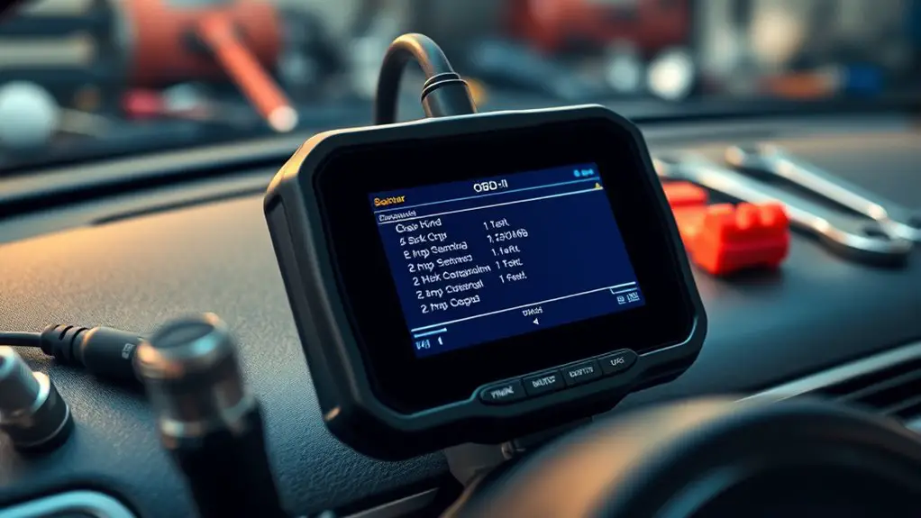
DTC Sources in Focus
DTC sources aren’t a single origin; start by separating what the scan tool reports from what the vehicle’s network actually confirms. You’ll map DTC origin to the vehicle’s data paths, then build a clear DTC hierarchy that ranks fault signals by reliability. Identify DTC types to distinguish between generic faults and OEM-specific codes, reducing misinterpretation. Conduct a focused DTC analysis, cross-checking live data, freezes, and history to spot inconsistencies. Use DTC correlation to relate codes across modules, sensors, and actuators, clarifying fault chains. This disciplined approach sharpens DTC interpretation, ensuring you don’t chase phantom issues. Keep awareness that aftermarket modules can skew signals, so validate codes against coding, wiring, and harness context before decisions. Freedom comes with structured, evidence-based diagnosis.
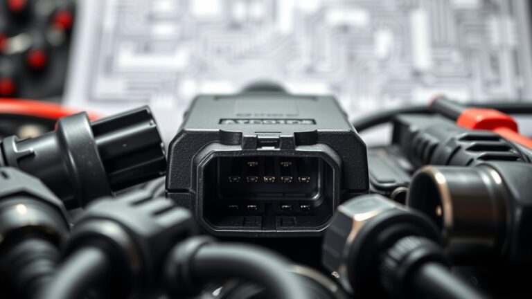
Module Communication Cautions
Module communication can derail a scan before you even interpret results, so start by verifying the basics: network topology, proper power and grounding, and the integrity of connectors and harnesses.
Table:
| Factor | Action |
|---|---|
| Module compatibility | Confirm aftermarket parts match OEM specs and ECU expectations |
| Communication protocols | Verify bus type (CAN, LIN, K-Line) aligns across devices and tools |
| Signal integrity | Inspect wiring, shields, and terminations for noise or opens |
Next, document any deviations, and isolate devices one at a time. Misfits here skew data, mask faults, or trigger false DTCs. Maintain a clean baseline, recheck after swaps, and reconcile diagnostics with expected protocol behavior. Your goal is a stable, coherent network where aftermarket modules speak the same language as the vehicle. Freedom comes from disciplined verification, not guesswork.
Interpreting OBD-II Error Codes With Aftermarket Gear
You’ll start by recognizing how aftermarket code nuances can alter standard OBD-II interpretations and what that means for your diagnostics. Next, you’ll compare sensor data across sources to spot discrepancies that signal timing, scaling, or wiring issues. Finally, you’ll apply fault-code validation techniques to confirm which codes reflect real faults versus aftermarket artifacts.
Aftermarket Code Nuances
When you’re dealing with aftermarket gear, interpreting OBD-II error codes requires distinguishing code meanings from the sensor and wiring quirks that come with non‑OEM parts, adapters, and tuners. You’ll map codes to real faults, not to every aftermarket oddity. Start with documented OEM PIDs, then flag deviations likely caused by modules or adapters rather than a true engine issue. Verify module compatibility before chasing a fault; mismatches can surface spurious codes. Record observed patterns across sessions to separate intermittent faults from persistent ones. Consider how aftermarket reliability influences code interpretation, noting when a fault code may be exaggerated by a second-hand module or bypassed sensor. Use a disciplined, repeatable procedure to avoid chasing symptoms that stem from installation quirks rather than actual drivability concerns.
Sensor Data Discrepancies
Sensor data discrepancies with aftermarket gear demand a disciplined approach: differences between actual sensor readings and OEM expectations often stem from non‑standard wiring, adapters, or altered signal conditioning rather than a true engine fault. You’ll assess sensor accuracy, calibration challenges, and data integrity before chasing faults.
- Verify compatibility issues and installation errors that can distort readings, then compare against manufacturer specifications.
- Check for signal interference, software updates, and potential diagnostic limitations that alter perceived performance variations.
- Evaluate ongoing calibration effects, data integrity, and OEM benchmarks to distinguish legitimate faults from calibration drift or hardware mismatches.
Keep notes on sensor data trends, document any calibration adjustments, and respect software version differences. When in doubt, revert to known good configurations to preserve diagnostic reliability while prioritizing freedom and precise interpretation.
Fault Code Validation Techniques
As you move from evaluating sensor data to fault code validation, the focus shifts to how OBD-II codes map to aftermarket components. You validate codes by confirming consistency across sources, then cross-checking with live data from diagnostic tools. Start with a code’s category (P, B, C, U) and narrowing subcodes, noting any violations or partial matches. Compare factory expectations against aftermarket behavior; look for code quirks caused by nonstandard wiring, adapters, or reflashed modules. Use multiple tools to verify, including data stream views, freeze frames, and elevation of confidence through relative signal trends. Document discrepancies clearly, then re-test after adjustments. Fault code interpretation must be systematic, reproducible, and transparent, ensuring you distinguish genuine faults from aftermarket quirks while preserving component integrity and driver freedom.
Verifying Module Revisions and Compatibility
Verifying module revisions and compatibility is essential to assure your aftermarket setup performs reliably. You’ll verify revision tracking and module compatibility checks before trusting any data from scans or gauges. Precision here saves headaches later.
- Confirm revision tracking against OEM records to assure your module isn’t out of date or misrepresented.
- Cross-check firmware and calibration versions with the latest spec from the supplier and your vehicle’s service history.
- Validate functional expectations by correlating revision data with observed behavior, noting any discrepancies for follow-up.
Approach this methodically: keep a changelog of revisions, document the exact module IDs, and compare them to a trusted compatibility matrix. If a revision mismatch or unclear lineage appears, pause installation adjustments until you’ve reconciled it. This isn’t about paranoia—it’s about clean data, predictable performance, and the freedom to push your car’s capabilities with confidence. Remember: module compatibility checks and revision tracking are your first line of defense against unreliable readings and inconsistent behavior.
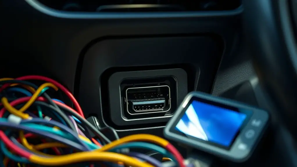
Common Connection and Grounding Issues to Inspect
After confirming revisions and compatibility, you’ll want to turn attention to the hardware connections that support reliable data flow. Begin with the power and ground harnesses: inspect for clean contact, tight connections, and absence of corrosion. Loose pins, bent connectors, or degraded seals create intermittent signals more than you’d expect. Next, verify chassis grounding isn’t isolated from engine/ECU grounds; a shared return path minimizes noise and prevents ground loops. If you find multiple ground points, unify them at a common star point, ensuring solid metal-to-metal contact. Check for damaged shielding on data lines and confirm shield continuity to chassis ground. Watch for voltage fluctuations during cranking or accessory load; spikes can masquerade as sensor faults. Measure with a stable reference, and compare readings across channels to spot inconsistency. Finally, document any observed resistance at connectors and replace fatigued harness segments before proceeding to diagnostics, because reliable data starts with robust, EMI-conscious grounding.
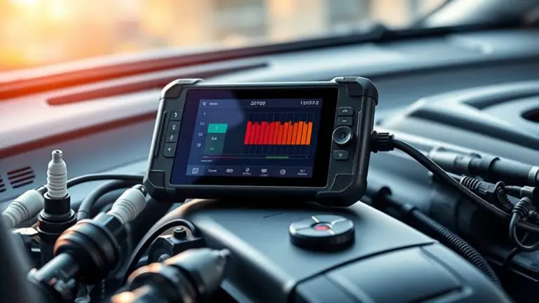
Data Stream Analysis: Reading Live PID/Live Data
Reading live PID/data streams is about clear, real-time insight into how the vehicle is actually behaving. You’re not guessing — you’re validating conditions directly from the ECU. Focus on clean, steady readings, and flag spikes that don’t fit the run condition. Use disciplined PID analysis techniques to separate sensor noise from meaningful trends, then map data to expected behavior.
1) Watch RPM, MAP/MAF, and IAT/O2 cross-checks simultaneously to confirm engine load and air/fuel balance.
2) Compare commanded versus actual values to reveal actuator or sensor faults during shifts.
3) Track long-term fuel trims and misfire indicators to distinguish intermittent faults from persistent failures.
Data stream analysis: read multiple PIDs in concert, note correlation, and document anomalies with timestamps. Stay precise: prioritize stable samples, filter noise, and label suspicious patterns for deeper review. This approach empowers you to assess aftermarket modules without guessing, maintaining control and clarity while chasing true faults.
Targeted Diagnostic Techniques for Fault Isolation
Targeted diagnostic techniques for fault isolation focus your investigation on the most probable causes, using structured, repeatable steps. You’ll begin by defining observable symptoms and correlating them with VIN-level and module-level data. Establish a baseline from trusted components, then compare against suspect aftermarket modules. Use fault isolation strategies that prioritize contextual clues: code histories, freeze frames, and known failure modes. Plan tests that are incremental and verifiable, minimizing variables so you can attribute anomalies to single sources. When selecting tools, emphasize diagnostic tool selection that supports real-time PID streaming, ECU reflashability checks, and non-destructive input/output probing. Systematically swap, bench-test, or isolate channels one at a time, recording outcomes for each branch of the decision tree. Document evidence clearly to prevent ambiguity during decisions. Maintain focus on reproducible results, traceable steps, and safeguards that protect vehicle systems while exposing faults beyond superficial symptoms.
Update Mismatches and Firmware Considerations
When you’re comparing suspect aftermarket modules, firmware mismatches often surface as subtle, non-deterministic faults that aren’t explained by hardware alone. You’ll focus on update protocols and firmware upgrades to verify compatibility before drawing conclusions. Treat each module as a potential variable, and document every version you encounter.
- Verify firmware lineage: confirm exactly which build and release date your ECU interface expects, and compare against the module’s reported version.
- Cross-check update methods: ascertain the supplier’s update process aligns with your vehicle’s OBD-II interface standards and that safeguards (rollback, verification hashes) are in place.
- Validate post-upgrade behavior: re-scan the same fault, monitor for resolution or new anomalies, and note any timing or sequence sensitivities that emerge.
Safe Testing Practices and Risk Mitigation
Safe testing starts with a formal plan that defines scope, success criteria, and rollback procedures before you touch any hardware or firmware. You’ll establish testing protocols that cover the entire workflow from initial inspection to final validation, ensuring repeatability and traceability. Approach each step with a clear check-in, documenting conditions, expectations, and contingencies. Conduct a thorough risk assessment to identify potential damage to the vehicle, the module, and your data integrity, then prioritize mitigations accordingly. Use isolated environments when possible and keep external power sources stable to avoid spikes. Maintain a controlled baseline by comparing against known-good references and recording deviations promptly. Limit high-risk actions, like live diagnostics, to structured, consented scenarios with rollback paths. Communicate findings succinctly to stakeholders, preserving transparency and accountability. Remember, safety isn’t a constraint but a foundation for reliable insight and freedom to explore complex aftermarket integrations responsibly.
Frequently Asked Questions
How Do Aftermarket Modules Affect CAN Bus Signaling Integrity?
Aftermarket modules can degrade CAN bus signaling integrity by introducing signal interference and timing jitter, especially if their outputs aren’t compatible with your vehicle’s CAN transceiver. You’ll want to verify module compatibility, ascertain proper grounding, and check termination resistors. Keep watch for corrupted frames or abnormal arbitration. If interference persists, isolate the module, re-test, and consult reliable schematics. A disciplined, methodical approach protects you from systemic faults and preserves network reliability.
Can Faulty Modules Trigger Non-Obvious Fuel Trim Anomalies?
Yes. Faulty modules can trigger non-obvious fuel trim anomalies. You’ll see abrupt zigzags or slow drifts in fuel trim as the ECU tries to compensate for erratic signals. Check module compatibility first, then verify sensor inputs and CAN signaling integrity. Use precise, stepwise tests: swap suspected modules, log live fuel trim, compare to baseline, and rule out wiring faults. Maintain a pragmatic mindset while preserving your freedom to question each result.
Do OEM Diagnostic Tools Detect Aftermarket Firmware Deviations?
OEM tool compatibility varies; some OEM tools can detect aftermarket firmware deviations, but not all. You’ll want to run checks that compare firmware stamps, boot loaders, and signature hashes to factory baselines. If deviations show up, investigate with caution. Look for logs on aftermarket module reliability, and verify that calibration data matches intended hardware. Maintain transparency with your team, and document any non-compliant findings to guide safer, freedom-loving diagnostics.
What Safety Margins Exist for High-Impedance Sensor Feeds?
Safety margins exist for high-impedance sensor feeds, with careful calibration keeping sensor voltage variations within defined impedance threshold levels. You’ll protect data integrity by maintaining consistent impedance, shielding signals, and monitoring drift. Start by setting tight tolerance windows, then log fluctuations, validate with reference volts, and adjust as needed. You’ll notice that small, steady signals matter—sensor voltage variations should remain within safe bands to safeguard accuracy, reliability, and freedom to troubleshoot boldly.
Are There Ghost Codes Unique to Non-Oem Hardware?
Yes, ghost codes can appear with non-OEM hardware. You’ll see them as intermittent or inconsistent fault indicators that don’t map cleanly to OEM fault trees. When using aftermarket hardware, you should verify code legitimacy by cross-checking with OEM data, clearing transient codes, and logging live sensor data. If a code persists without clear symptom, suspect ghost codes from timing or communication quirks in aftermarket hardware. Document findings, revert to known-good modules if doubt remains.