How to Interpret OBD Adapter Connection Failure When Scanning a Modern OBD-II Cars
You’ll start by separating adapter faults from software limits, then verify power and ground integrity before any data checks. Confirm the connector type, protocol match, and that the adapter supports the vehicle’s baud rates and voltage. Inspect physical cables, pins, and shielding for damage. Check Bluetooth, Wi‑Fi, or USB interfaces and note any error messages. Make certain the ECU is awake and ready, with correct baud and CAN IDs. If issues persist, you’ll uncover more as you continue.
Diagnosing Adapter vs. Software Mismatch
When diagnosing an OBD adapter issue, start by separating potential hardware faults from software incompatibilities. You’ll approach this with a methodical checklist, focusing on adapter compatibility first. Verify that the connector type and protocol match your vehicle’s OBD-II standard, then confirm the adapter’s stated supported baud rates and voltage range. If the physical link appears sound, isolate software factors next: verify the scanning app is current, and the device’s OS supports the adapter’s drivers. Perform a controlled test using a known-good cable and another device to rule out platform-specific quirks. Document any error codes or handshake failures, correlating them to whether they occur before or after the handshake completes. In parallel, assess software updates and firmware revisions from the manufacturer; apply updates only if they address connection stability. Maintain a clear changelog to track what resolved or caused the mismatch, reinforcing troubleshooting discipline while preserving system freedom.
Confirming Power Supply and Ground Integrity
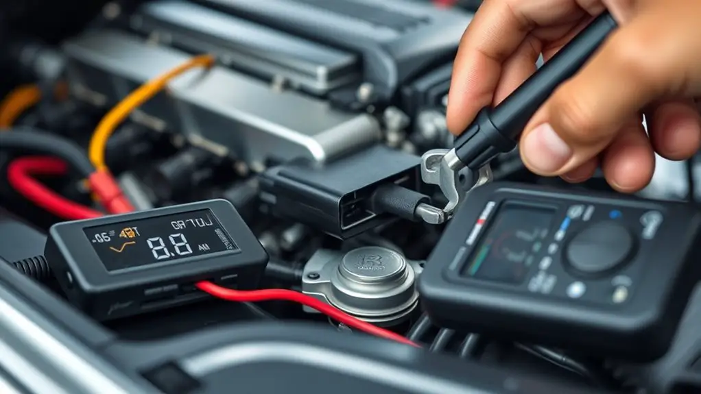
Start with a precise check of the power supply and ground paths to the OBD adapter, confirming you have stable 12V (or vehicle-appropriate) and a solid common ground. Verify ground integrity by measuring continuity from the OBD connector shell to a known chassis point, noting any high resistance or intermittent contact. Document results and proceed to targeted tests if either the power or ground path shows deviations.
Power and Ground Check
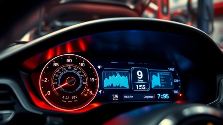
Power and ground integrity is essential for a reliable OBD adapter connection. You verify power and ground by tracing the supply from the vehicle’s fuse box to the OBD port and inspecting the return path for noise or interruption. Check for a stable power source within 12–14.5 V under load, and guarantee ground contact is solid with minimal resistance. Look for a single, low-impedance ground path to avoid a ground loop that can introduce erratic readings. If voltage or continuity falters, reseat connectors or test another known-good cable. Document measurements and replace faulty components as needed.
| Step | Action | Expected Result |
|---|---|---|
| 1 | Measure voltage | 12–14.5 V under load |
| 2 | Test continuity | Low resistance to chassis |
| 3 | Inspect connectors | Clean, snug, corrosion-free |
| 4 | Check ground path | No ground loop signs |
| 5 | Retry scan | Stable, repeatable readings |
Ground Integrity Verification
Ground integrity verification centers on confirming a stable power supply and solid electrical grounding before any OBD communication attempts. You’ll methodically verify supply rails and ground references to prevent erroneous reads and misdiagnoses. Focus on consistent voltage, clean connections, and low impedance paths; any fluctuation can masquerade as sensor errors. Incorporate quick checks that you can trust under field conditions, not just lab ideals. Ground testing and sensor checks form the backbone of reliable diagnostics, ensuring the MCU and transceiver operate within spec. Maintain an evidence trail for reproducibility. In practice, confirm voltage at the OBD port, inspect harness continuity, and verify chassis and battery grounds are sound and bonded.
- Probe power quality and continuity
- Validate ground integrity and routing
- Confirm sensor references are stable
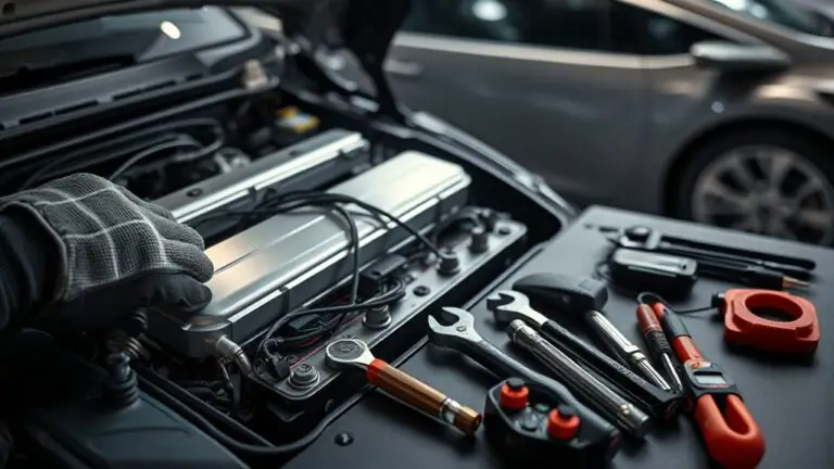
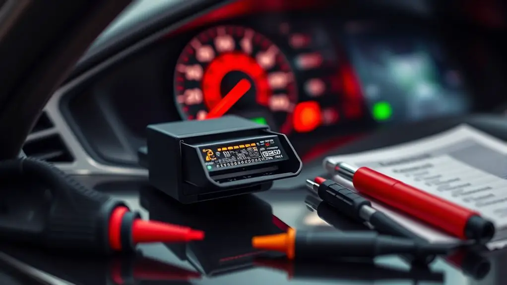
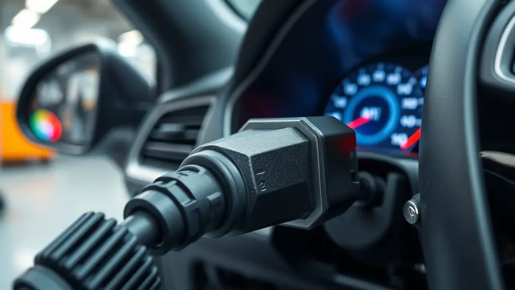
Checking Physical Connections and Cable Quality
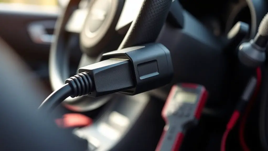
Begin with a quick visual and physical check: confirm that the OBD adapter is firmly seated in the vehicle’s OBD port and that the other end is securely connected to your scanning device. You’ll assess cable quality through a concise, methodical sweep: inspect the whole cable for visible damage, kinks, or cracks; verify that pins are intact and free of corrosion; confirm there are no loose connectors at either end. Emphasize cable inspection as a routine step before deeper diagnostics, since hidden defects can disrupt data integrity. Check that shielded, properly rated cables are used for the interface and that the length isn’t unnecessarily long, which can introduce signal loss. Maintain a stable physical setup by minimizing tension or strain on the connectors during measurement. Document any irregularities and replace suspect cables promptly to preserve connection stability and reliable readings. This disciplined approach supports rapid troubleshooting without sacrificing freedom of movement.
Verifying Bluetooth, Wi-Fi, or USB Interfaces
Start with a quick Bluetooth status check to confirm pairing and signal strength, then verify Wi‑Fi connectivity using a stable network name and IP assignment. For USB, confirm that the interface is recognized by the host computer and that the OBD adapter shows as a connected device with a valid port. If any of these checks fail, document the exact error message and proceed to targeted troubleshooting for each interface.
Bluetooth Status Check
To begin the Bluetooth status check, verify that the adapter is powered and that Bluetooth is enabled on the host device; this establishes the baseline for successful pairing with the OBD unit. You’ll assess link quality before code exchange, confirming that Bluetooth connectivity issues don’t mask protocol errors. Inspect device visibility, ascertain pairing procedures match the adapter’s requirements, and verify Bluetooth version compatibility to avoid stale profiles. If pairing fails, check signal integrity and retry at a shorter range to rule out interference.
- Confirm Bluetooth signal strength is within ideal range and stable
- Validate that pairing procedures follow the adapter’s documented steps
- Verify compatibility across Bluetooth versions and profiles for the pairing process
Wi-Fi Connection Tips
What’s the quickest way to confirm a stable network path for your OBD adapter: Wi-Fi, Bluetooth, or USB? Begin with a direct test of the Wi Fi signal strength and proximity to the router. Verify Network stability by pinging a known gateway and checking latency consistency across multiple attempts. Observe for Connection interference from competing networks or devices, and note any dropped packets or jitter. Check Adapter compatibility by confirming the OBD adapter firmware recognizes your network band (2.4 GHz vs 5 GHz) and matches encryption settings. Disable nonessential devices during tests to isolate fluctuations. Document results, then retry with adjusted channel, enhanced signal placement, or a reset sequence if instability persists. Precise measurements guarantee reliable communications and freedom in troubleshooting.
USB Interface Basics
As you move from validating network paths to the USB interface, focus on how the OBD adapter communicates over a wired connection. USB interface basics cover how usb protocols and interface types determine data flow, power, and reliability. Verifying physical connectivity and stream integrity helps isolate faults before software retries. You should confirm that the host device recognizes the adapter, drivers are current, and the cable is capable of data transfer. When issues persist, test alternate ports or hubs, and inspect voltage availability and enumeration order. Pay attention to message timing, baud-like constraints, and protocol handshakes to avoid stall conditions.
- Check usb protocols support and interface type compatibility
- Validate device recognition, driver status, and power delivery
- Test multiple ports, hubs, and cable quality for reliability
Understanding Vehicle Readiness and ECU States
Vehicle readiness and ECU states describe whether the engine and related systems have completed required self-checks and can perform normally. You assess these conditions to determine if a scan can proceed without false failures. Vehicle readiness aggregates multiple monitors that reflect ongoing diagnostic confidence, while ECU states indicate the current mode of each control unit. When you connect an OBD adapter, your first task is to observe the readiness flags for monitors such as combustion, misfire, and catalyst. Not all monitors report simultaneously; some require startup, stable temperature, or specific driving patterns. If monitors are not ready, a scan may yield misleading results or require a retry after a defined drive cycle. Document the readiness status and note any inactive or pending monitors. Understanding how these indicators interact helps you distinguish genuine faults from temporary, system-initialization conditions. In practice, rely on documented ECU state codes to interpret what portion of the diagnostic suite is available to your scan.
Interpreting Common ECU Initialization Errors
Interpreting common ECU initialization errors requires distinguishing between temporary boot glitches and genuine faults that block diagnostic access. You’ll assess whether the issue arises during ECU wake/handshake, baud rate negotiation, or CAN message framing, then confirm expectations against the vehicle’s wiring and power stability. Focus on reproducible symptoms, known error codes, and consistent timing, not rumors or guesswork. Document the sequence of attempts, noting any intermittent responses or corrupted frames.
- ECU communication: verify that the controller responds to a safe wakeup, and check for proper baud rate, CAN IDs, and termination resistors.
- Error codes: map codes to probable subsystems (engine, transmission, or body) and verify against the OEM fault tree.
- Initialization timing: distinguish solo boot delay from locked ECU state, and watch for repeated resets that suggest secure or memory faults.
Use this framework to decide whether you’re dealing with a transient glitch or a fault that requires deeper diagnostics.
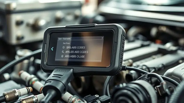
Troubleshooting Security Blocks and Manufacturer Restrictions
Even with a functional OBD interface, security blocks and manufacturer restrictions can prevent access to certain PID groups, fault records, or extended diagnostic data. You’ll encounter these controls as layered gates: vehicle security protocols, ECU-specific permissions, and vendor-signed data demands. To proceed, verify your access permissions against the vehicle’s policy and the diagnostic tool’s authorization level. Confirm the tool supports the required OBD-II modes and PID ranges; some data requires elevated privileges or a sanctioned subscription. When a block appears, document the exact PID or data set denied, then consult the dealer or OEM documentation for permissible alternatives. Use diagnostic tools capable of presenting a transparent access audit trail, including timestamps and user credentials. If you suspect a manufacturer limitation, test with a different vehicle or a tool known to respect the same security constraints, ensuring you remain compliant with applicable laws and licensing. Maintain a precise, methodical approach to avoid misinterpretation of restricted data.
Cross-Platform Compatibility Considerations
Cross-platform compatibility matters because the same OBD workflow can behave differently across tools, operating systems, and device ecosystems. You assess adapter compatibility by validating interface standards, baud rates, and power profiles across environments before committing to a workflow. Software integration must be evaluated for driver support, USB/BT stack behavior, and update cadence, since inconsistencies create flaky connections and misreported data. Your goal is consistent data capture, reproducible results, and predictable error handling across platforms.
- adapter compatibility checks: verify protocol support (ISO, CAN), voltage tolerances, and firmware update paths for each platform you intend to use.
- software integration considerations: compare session management, request/response timing, and logging formats to guarantee uniform analytics across tools.
- cross-platform validation methodology: establish a baseline dataset, run repeatable tests, document platform-specific quirks, and maintain versioned configurations.
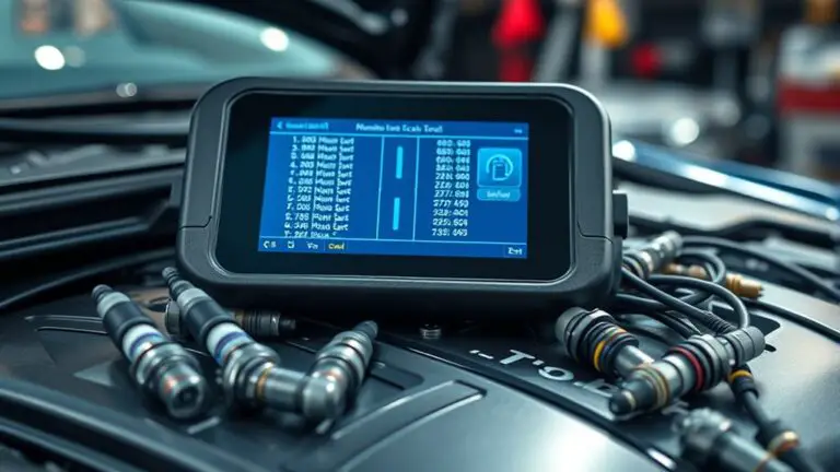
Steps to Validate Codes and Retrieve Data Safely
To validate codes and retrieve data safely, start with a controlled test plan that verifies fault-free code execution, confirms data integrity, and guarantees proper error handling. You’ll structure tests around three pillars: code validation, data retrieval, and fault simulation. For code validation, use representative OBD-II PIDs and common fault scenarios, asserting that the scanner returns expected codes within defined ranges and that no residual states persist between runs. For data retrieval, verify timestamping, unit consistency, and data freshness across multiple sessions, ensuring that live values and freeze-frame data align with vehicle specifications. Implement strict error handling for timeouts, checksum failures, and unsupported PIDs, logging each incident with context for traceability. Validate the complete workflow end-to-end on a known-good vehicle first, then re-run on edge cases to confirm resilience. Document results, repeatability, and any deviations to guarantee reliable interpretation of codes and data.
Frequently Asked Questions
How Do I Tell if the OBD Adapter Is Counterfeit or Low Quality?
Yes, you can spot a counterfeit by checking adapter features against claimed specs and looking for build quality issues. If the device feels cheap, the plastic flexes, or the connectors wiggle, suspect. Verify data transfer speeds and reliability with a calibrated test, and run counterfeit detection routines when possible. Compare device IDs to official listings, and beware mismatched firmware. If in doubt, choose trusted brands with robust counterfeit detection and documented warranty.
Can Different OBD Apps Misinterpret Error Codes From the Same ECU?
Yes. Different OBD apps can misinterpret error codes from the same ECU due to error code discrepancies and app compatibility issues. Think of it like using multiple translators on a single manual: meanings shift. You’ll see mismatched fault IDs, varying data granularity, and delayed or missing live streams. To mitigate, cross-check with the ECU’s raw PIDs, standardize the library, and verify firmware/app versions before drawing conclusions.
What Firmware Updates Could Cause a Temporary Scan Failure?
Firmware updates can temporarily break compatibility, causing scan failures. You’ll see connection drops if a new build alters protocol handling or timing. Check firmware compatibility issues before updating and review changelogs for ECU support changes. The update frequency impact matters: frequent updates raise risk of transient incompatibilities; sporadic releases reduce risk but may delay fixes. If you hit a failure, roll back to a known good version, verify protocol support, then re-test with a stable adapter and settings.
Do Vehicle Trim Levels Affect OBD-II Compatibility or Data Access?
Sure, trim level differences can influence data access, but they don’t change the OBD‑II protocol itself. You’ll encounter compatibility issues only if a vehicle’s ECU implements vendor-specific PID sets or enhanced modes not required by OBD‑II. In practice, you may see limited data or missing parameters on certain trims. You should verify scanner support for manufacturer PIDs and expect uniform OBD data, with extras gated by platform-specific access.
How Can I Test Adapter Performance Without a Vehicle Present?
To test adapter performance without a vehicle present, you perform bench tests using a calibrated simulator or OBD-II emulator. Connect the adapter, run diagnostic software, and measure responses to standard PIDs. Key steps: verify power, grounding, and LED indicators; confirm baud rate compatibility; log response times and error codes. Adopt adapter testing methods that quantify latency, packet loss, and retry behavior. Monitor performance indicators such as successful frame rate and stability under load, then document results.