How to Prepare Your Car and Tools Before Tackling PCM Reflash Needed
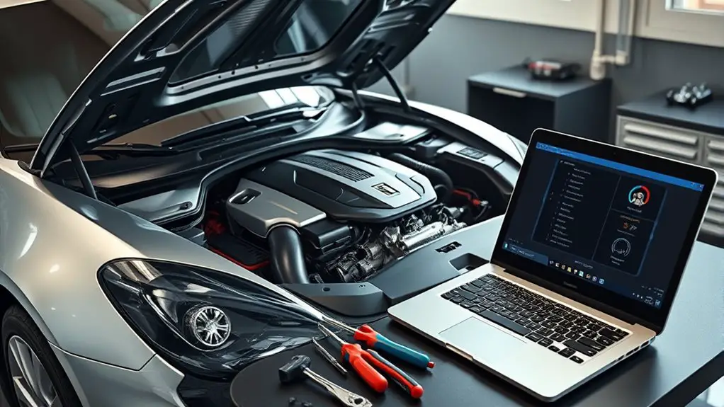
Before you tackle a PCM reflash, verify compatibility and back up current ECU data. Gather essential tools, safety gear, and a stable power plan, then disconnect the battery and isolate the negative terminal. Tag and organize wiring with unique codes, and secure clean, labeled connections. Create a detailed, dependency-based reflash plan with owners and timelines, plus a rollback option. Guarantee a controlled environment with proper lighting and ESD precautions. If you keep going, you’ll uncover more critical steps and safeguards.
Verify PCM Compatibility and Data Backup
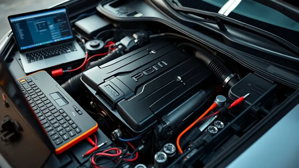
Before reflashing the PCM, confirm compatibility with your vehicle’s year, model, and engine configuration, and verify that the new software is specifically designed for your PCM part number. You’re evaluating PCM compatibility and data integrity with focus and discipline. Begin with a PCM specifications review to establish baseline expectations: confirm firmware version, calibration ID, and mapping against OEM documentation. Then perform Compatibility testing by validating the software’s checksum, driver support, and flash protection status, ensuring no conflict with existing modules or immobilizer logic. Document current PCM state, including mileage-accurate VIN binding and last processed calibration, to enable traceable rollback if needed. Prioritize data backup strategies: create a full backup of current firmware, flash memory sectors, and key calibration data, and store copies securely. Confirm recovery options, including safe-mode boot and reflash rollback. Maintain an auditable checklist to verify readiness, reducing risk while preserving control over your vehicle’s tuning trajectory.
Gather Essential Tools and Safety Gear
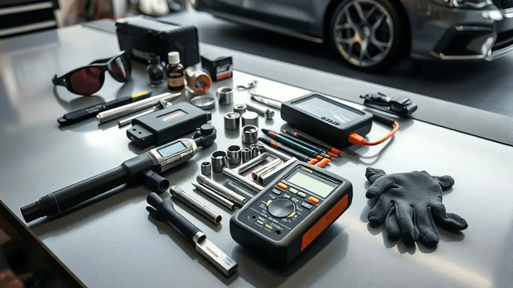
To proceed safely and efficiently, assemble a targeted toolkit and protective gear tailored to your PCM reflashing workflow. Begin with core tools: multimeter, insulated pliers, a precision screwdriver set, and a magnetic pickup for quick fastener retrieval. Include a torque wrench for reassembly accuracy and a non-contact voltage tester to confirm circuit status without contact. Organize cables, adapters, and jumper leads in labeled trays to support tool organization and rapid access. Add a reliable power supply or bench supply with current limiting to prevent voltage spikes during reflashing. For safety gear, choose flame-resistant glasses, cut-resistant gloves, and a breathable, anti-static lab coat. Keep a clean work surface and use anti-static mats to minimize ESD risk. Maintain a small first-aid kit and a fire extinguisher suitable for electrical fires within arm’s reach. Plan storage so tools return to their place after use, preserving tool organization and safety gear readiness for the next session.
Disconnect Power Sources and Protect the Battery
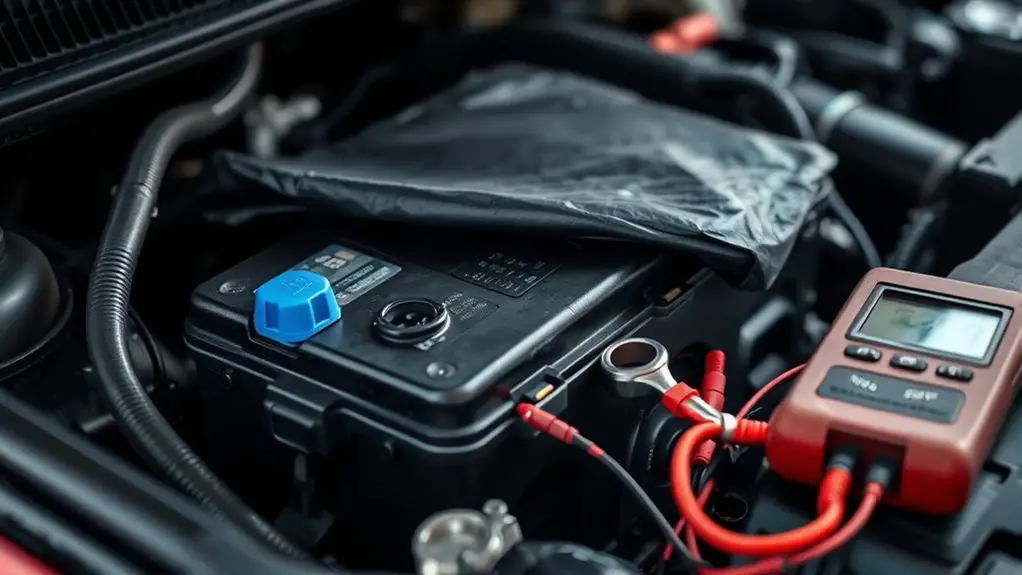
Next, you’ll establish a safe baseline by disconnecting power sources and protecting the battery. Begin by locating the main battery disconnect or removing the negative terminal to prevent backfeed. If your vehicle uses a hybrid or start-stop system, consult the manual for cautions and follow the manufacturer’s sequencing to avoid parasitic drain. With power isolated, inspect for any residual load: lights, radios, and accessories should be off; doors closed to prevent memory drain. Document current battery state and confirm no exposed conductors are reachable during work. Prioritize battery maintenance by shielding terminals from moisture and corrosion, and keep tools insulated from metal surfaces. Implement a conservative power management approach: avoid long, unattended electrical tests, and recheck connections after reassembly. This discipline minimizes risk to ECU memory and keeps the PCM reflashing environment stable, supporting precise calibration and reliable performance.
Tag, Label, and Organize Wiring and Connectors
Once you’ve isolated power, systematically tag, label, and organize all wiring and connectors to prevent mix-ups during the reflash. Begin with a simple scheme: assign unique codes for each harness, accessory, and sensor group, and attach durable tags near every termination. Use connector labeling that stays legible in workshop conditions—thermal labels or engraved tags work well. Maintain a consistent orientation by marking pin side, mating side, and flow direction where applicable. Create a wiring map as you go: note color, function, and counterpart, then store it with the chassis schematic. Group related circuits in logical bundles, secured with reusable zip ties and labeled sleeves. Avoid crossovers that could cause misconnection; route away from heat sources and moving parts. This wiring organization framework supports quick troubleshooting and reduces error during reflash. Keep references accessible, update diagrams as changes occur, and maintain discipline in every tagging decision.
Create a Step-by-Step Reflash Plan and Timeline
A clear, step-by-step reflash plan keeps the process focused and repeatable: begin with a written scope, then sequence tasks in order of dependency, assign owners, and set exact start and end times. You’ll translate the scope into a concrete reflash timeline, then map each task to a dependency and a responsible person. A precise plan eliminates guesswork, reduces risk, and keeps momentum intact.
| Phase | Key Deliverable |
|---|---|
| Preparation | Confirm tools, data, and safety checks |
| Execution | Perform reflash steps in sequence |
| Validation | Verify results and document outcomes |
This approach makes the reflash a structured, auditable process. You’ll maintain momentum, track progress, and adjust only when necessary. Keep the step by step guide visible, update owners, and align dates. The goal is repeatability that scales to future reflashes, preserving freedom to adapt while preserving control. Remember, a solid plan reduces surprises and clarifies responsibilities throughout the reflash timeline.
Establish a Clear Rollback Strategy and Recovery Options
You’ll outline rollback steps that are clear and repeatable, so you can revert quickly if the reflash fails. Consider ready recovery options that cover both firmware and configuration, and guarantee you can activate them with minimal tools. This establishes a disciplined path to restore functionality, minimizing downtime and risk.
Rollback Steps Clearly
To minimize risk, establish a rollback plan before flashing the PCM, outlining when to stop, how to revert, and who approves changes. You’ll define verified rollback techniques ahead of time, ensuring you can restore a known-good state if the procedure stalls or faults appear. Document rollback scenarios, including driver version mismatches, partial flash completion, and power loss, so you respond quickly and deterministically. Keep a concise checklist: confirm power stability, confirm tool integrity, log each step, and verify post-flash baselines. Use non-destructive testing to validate modules before and after attempts. Maintain clear access controls, so approvals are traceable. Practice the sequence in a controlled environment, then apply it with precision during real-world reflashes. This clarity preserves your freedom to act with confidence.
Recovery Options Ready
Recovery options should be defined upfront and kept ready, so you can respond decisively if something goes awry during a reflashing event. You’ll scaffold a rollback by selecting reliable recovery software and testing it in advance. Verify you can boot from a dedicated recovery partition or external media, and confirm that essential drivers load without conflict. Create verified backups with preserved timestamps and checksum validation. Maintain intact backup devices that stay powered and protected from corruption, and store copies off the vehicle where practical. Document a simple, repeatable sequence: halt, verify, restore, and confirm vehicle control readiness. Keep tools organized, updates tracked, and rollback timing estimated to minimize risk. This disciplined preparation preserves freedom: you choose when and how recovery occurs.
Prepare a Controlled Environment and Safety Measures
Establish a controlled environment and implement safety measures before reflashing the PCM. You’ll create a stable workspace, free from interruption, heat, and moisture. Clear clutter, organize tools, and designate a clean bench area for sensitive electronics. Use anti-static mats and wear a grounded wrist strap to prevent damage from static discharge. Ascertain proper lighting and ventilation, avoiding fumes from solvents or adhesives. Disconnect the vehicle battery and isolate the negative terminal; verify power-down status before handling connectors. Have fire safety gear accessible and know how to respond to emergencies, including a charged fire extinguisher suitable for electrical fires. Keep a calibrated multimeter, insulated tools, and nonconductive trays on hand to minimize shock risk. Document initial conditions and set a consistent procedure, preventing mid‑reflash surprises. Maintain a quiet, controlled environment where interruptions are minimized, and focus remains on procedure integrity. Safety measures protect you and the vehicle, enabling precise, repeatable reflashing.
Perform a Pre-Flash System Check and Documentation
Before proceeding with the flash, perform a thorough pre-flash system check and documentation: verify the vehicle’s status, record baseline data, and confirm all connections and power conditions are suitable for reflashing.
- pre flash checklist: confirm battery health, charging stability, and tool compatibility
- system diagnostics: run ECU/PCM status, fault codes, and sensor health
- document baseline measurements: voltage, current, temperatures, and module timestamps
- verify wiring integrity: secure grounds, connector cleanliness, and isolation from moisture
- capture environment notes: ambient conditions, power source, and timing constraints
Proceed with documented results: if any parameter deviates, pause and remediate before attempting the flash. Maintain a concise log entry for each step, including who performed it and when. This discipline reduces risk, clarifies accountability, and preserves a verifiable trail for future reference. A disciplined pre-flash routine supports reliable reflashing and aligns with a freedom-forward mindset that values control and clarity.
Frequently Asked Questions
How Long Does a Typical PCM Reflash Take End-To-End?
A typical PCM reflash takes about 45 minutes to 2 hours end-to-end, depending on vehicle and software. You should plan for potential delays. PCM reflash duration can extend if the vehicle stalls, requires multiple attempts, or if you encounter compatibility checks. Start with reflash preparation steps: backup data, guarantee stable power, and verify tools. You’ll appreciate a methodical workflow, keeping you in control and preserving momentum throughout the process.
What Are Common Signs of a Failed Reflash?
Common signs of a failed reflash include stalling, loss of power, inconsistent idle, error codes, and failure to start. You’ll notice ECU not recognizing tuning changes, or prompts to reflash again. For clear steps, rely on reflash troubleshooting tips: verify power stability, check battery voltage, inspect data connection integrity, and reattempt with verified ROM file. If symptoms persist, back up data, consult factory logs, and avoid aggressive driving until reset is confirmed.
Can Reflash Affect Vehicle Diagnostics and ABS Systems?
Reflashing can influence diagnostic impact and ABS functionality. You’ll want to know that transient glitches may trigger warning lights or misread sensors, but proper reflash procedure minimizes risk. It’s like recalibrating a compass—precision matters. You should verify integrity of the PCM and ABs after completion, run diagnostics, and clear codes. If codes recur, recheck wiring, modules, and power stability. Stay methodical, document steps, and maintain freedom by testing each system before road use.
Is Dropout Risk Higher With Aftermarket Tuners?
Yes, dropout risk is higher with aftermarket tuners. You’ll face variability in tuning quality and compatibility, which can destabilize PCM behavior. To minimize risk, scrutinize aftermarket reliability, verify data sources, and choose tuners with robust error handling and proven race/testing results. You should document changes, monitor live parameters, and revertable maps. Stay analytical, methodical, and selective; freedom comes from informed choices, not guesswork.
How Do I Verify Post-Flash Functional Readiness?
Think of it like testing a ship after a new sail goes up: you verify every seam before you sail free. You should perform a post flash checklist, then run functional testing to confirm idle, throttle response, shifting, and gauges are normal. Check for diagnostic codes, readiness monitors, and data stream integrity. If anything spikes, repeat tests, reset logs, and document deviations. You’re ensuring predictability, not bravado, before you roll.

