How to Safely Disconnect and Reconnect SRS Components
To safely disconnect and reconnect SRS components, start by de-energizing the system and securing power sources, then verify zero energy before touching any parts. Identify each connector, release tabs gently, and label as you go to prevent misassembly. Inspect housings and wiring for damage, clean contacts with approved methods, and reseat components with proper orientation. Power up incrementally, check signals and continuity, and document results. If issues appear, stop and proceed with guided checks—you’ll uncover more steps ahead.
Preparation and Safety Precautions
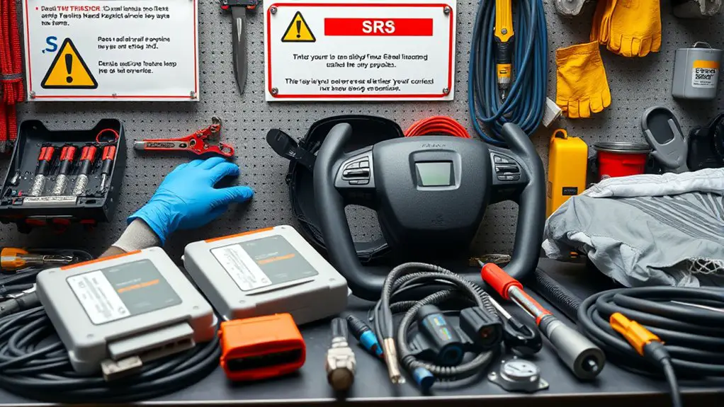
Before you touch anything, shut down the system, disconnect power, and remove the key or breaker; this step prevents stored energy from causing unexpected movement or shocks. You approach preparation with discipline, not hurry. Identify your environment: guarantee clear floor space, adequate lighting, and all nearby personnel aware of work. Wear personal protective gear appropriate to the task, and verify you have a reliable, current set of tools. Tool selection matters: choose insulated handles for any contact points, and steady, non-slip grips for control. Review schematics and labels to locate SRS components accurately, avoiding surface detours or guesswork. Establish a simple, repeatable checklist to confirm de-energization, grounding, and seating of any actuators. Maintain orderly organization: aline components, store fasteners, and note torque expectations. If a deviation occurs, halt, reassess, and document. Precision reduces risk; freedom is earned through careful preparation and disciplined caution.
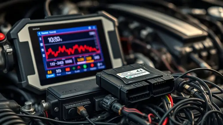
Power Down and Residual Charge Management
Powering down and managing residual charge require a deliberate, repeatable sequence to prevent unexpected motion or shocks. You’ll follow a calm, systematic cadence: secure the unit, disengage power sources, and verify zero energy states before any tray or panel access. Begin with a known power-off command, then isolate batteries or power rails using approved shutoff devices. After power down, perform residual charge management by measuring with a calibrated meter, confirming voltage under the safe threshold, and waiting the prescribed stabilization interval. Document readings and timestamp steps for traceability. Use proper PPE and keep hands clear of potential energy points during capacitive discharge checks. If a residual charge remains, employ manufacturer-recommended discharge tools and avoid shorting across components. Reconfirm absence of stored energy before proceeding to next steps. These power down procedures reduce risk, support repeatable maintenance, and align with a disciplined approach that respects both safety and operational freedom.
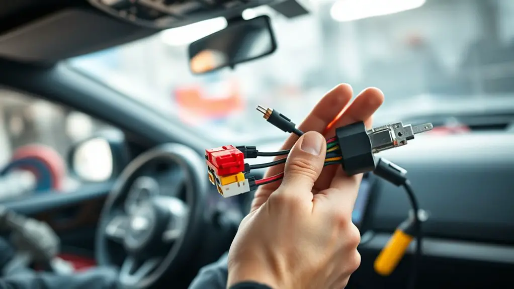
Disconnecting Connectors and Sensors
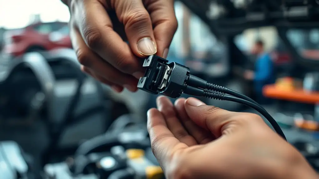
To disconnect connectors and sensors, you’ll proceed only after confirming the unit is secured and fully de-energized. You’ll identify connector types and verify release mechanisms before handling any plug. Gently detach connectors by avoiding lateral force; use the correct release tab or locking collar, and keep harnesses aligned to prevent pin damage. Note sensor locations and reference any service manuals to avoid mixing parts. Label each connector as you disconnect, documenting its destination and orientation for reassembly. Inspect for corrosion, dirt, or damaged pins, and clean only with approved methods if permitted. If a connector resists, don’t force it—back off, recheck alignment, and reattempt with even pressure. When removing sensors, support the component to prevent strain on wiring or mounting points. Recheck the work area for loose clips or debris, and store connectors in a orderly arrangement to preserve integrity. You’re preserving system reliability through deliberate, controlled steps.
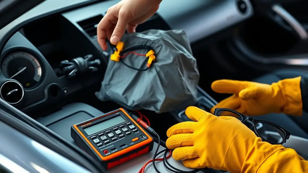
Inspection, Cleaning, and Reassembly
Next, you’ll inspect for integrity and cleanliness, then reassemble with care to preserve function. Begin with a calm, methodical sweep: verify fasteners are undamaged, housings free of cracks, and connectors snap securely. Wipe residue from contact surfaces without forcing components. When cleaning, use a lint-free wipe and isopropyl alcohol sparingly; avoid oversaturation near wiring. Inspect wiring insulation for nicks or brittle sections, replacing any suspect segments. During reassembly, align components to their original orientation; avoid cross-threading and overtightening. While pursuing reliability, confirm component compatibility by matching part numbers and markings to the service guide. Refer to wiring diagrams to reestablish proper routing, ensuring harnesses sit in channels without pinching. Reconnect sensors and modules in the exact sequence specified, then perform a tentative, low-load check to observe stable function. Document any deviations from the standard, and store tools in a clean, organized workspace for the next step. Maintain caution: precision protects both you and the system.
Verification and Post-Reconnect Testing
Following reconnection, perform a controlled verification to confirm all systems respond as expected; begin with a visual and tactile check of connectors, harness routing, and mounting hardware to guarantee nothing is misaligned or pinched. You’ll then power up incrementally, monitoring indicators and sensor signals for anomalies. Use clear, repeatable verification methods to validate electrical continuity, resistance, and grounding integrity across critical circuits. Document initial readings before engaging live functions, ensuring no unexpected offsets appear. Proceed with structured testing procedures, starting with low-risk subsystems before full-system activation. Check for unexpected alarms, lag, or abnormal behavior, and cross-verify with schematic references and fault lists. If deviations arise, isolate the affected module, recheck connections, and retest in a controlled sequence. Confirm that safety interlocks, retry limits, and protective guards respond correctly. Conclude with a concise pass/fail record, noting any required maintenance steps and follow-up verification windows to sustain reliable operation.
Frequently Asked Questions
How Do I Store Components After Removal Without Damage?
You should store components after removal by using proper storage containers, labeled and cushioned, to prevent impact and dust. Keep them in dry, static-safe environments, away from moisture and heat. Use anti-static bags for sensitive parts and seal containers tightly. Maintain an organized inventory, tracing dates and lot numbers. Handle with clean, dry hands and avoid bending connectors. This guarantees proper storage and component safety, preserving functionality while you pursue freedom to reuse or reassess.
Can SRS Components Be Cleaned With Standard Solvents?
Can you clean SRS components with standard solvents? Not reliably. You should avoid generic solvents because SRS component maintenance requires solvent compatibility checks, as many parts are sensitive to chemicals. Verify manufacturer guidance, test a small area, and use only approved solvents. If you must, document steps and observe safety precautions. In short, consult the compatibility chart first, then proceed with caution to prevent damage or performance issues.
What Are Common Signs of Hidden Connector Damage?
Did you know that up to 30% of unseen connector failures come from wear and corrosion? You’ll spot common signs of hidden connector damage by inspecting for bending, looseness, and discoloration. Look for connector wear and electrical corrosion on terminals, pins, and housings, especially at service points. Treat any dull or greenish residue as a red flag. If you see corrosion or looseness, pause and test continuity before powering up to avoid safety hazards.
Should I Replace Fasteners After Reconnecting Modules?
Yes, you should evaluate fastener integrity and follow replacement guidelines after reconnecting modules. Inspect each fastener for thread wear, corrosion, and proper seating. If any doubt exists, replace them rather than reuse. Keep to conservative replacement guidelines: use correct size, grade, torque, and thread-locking compound as specified. Document what you replaced and why. This approach protects system reliability while preserving your freedom to trust your work.
How Long to Wait Before Power-On After Reconnection?
Did you know that 52% of electronics failures occur during power-on events? You should wait at least 30 seconds after reconnecting SRS components before power-on. Verify all connectors are seated, then set SRS timer settings according to the manual. Initiate the power on sequence slowly, monitoring for abnormal indicators. If anything doubts arise, power down and recheck connections—precision matters, but you still value your freedom to troubleshoot confidently.