How to Stop Exhaust Manifold Leak Caused by Clogged O2 Sensor Heater
To stop an exhaust manifold leak caused by a clogged O2 sensor heater, first inspect the manifold area for leaks, soot, and heat discoloration, and verify wiring continuity in the heater circuit. Check heater resistance with a meter and compare to spec; test the heater circuit current and replace the heater element if needed. Clean and reseal joints, secure clamps, and verify proper routing after replacement. Then run a controlled cold start to confirm stability and watch for leaks, with more steps to follow.
Diagnosing an Exhaust Manifold Leak Related to O2 Sensor Heater

Diagnosing an exhaust manifold leak related to the O2 sensor heater involves inspecting the manifold area where the sensor plugs in and tracing symptoms back to the heater circuit. You’ll locate the O2 sensor, verify wiring continuity, and examine harness connectors for corrosion or damage. Measure for abnormal resistance in the heater circuit and compare against manufacturer specs. Observe exhaust gases escaping at the sensor port or along the wiring loom, noting odor, soot buildup, or heat discoloration. Use a diagnostic scan tool to confirm heater status flags and PCM fault codes related to sensor functionality. If codes indicate heater failure, isolate the circuit by unplugging the sensor and testing the supply voltage and ground integrity with the engine off. Check for voltage dropout under load, which can reveal wiring faults or blown fuses. Document findings, then proceed with controlled disassembly if needed, ensuring you maintain proper vibration isolation and prevent contamination of the sensor chamber.
Understanding How O2 Sensor Heaters Get Clogged

O2 sensor heaters can become clogged when contaminants in the exhaust stream or deposits from engine oil, fuel, or coolant disrupt the heater element or surrounding passages. You’ll verify how deposits form by analyzing oil traces, fuel dilution, and coolant intrusion that foul the heater circuits. The mechanism is largely deposition-driven: waxy or oxidized hydrocarbons adhere to heater surfaces, while ash and particulates abrade or obstruct microchannels. You’ll assess thermal cycling, which accelerates buildup at high exhaust temperatures, and examine how differential gas flow can concentrate deposits near the heater. Effective understanding hinges on recognizing how O2 sensor functionality depends on consistent microchannel openness, stable impedance, and rapid heating. For exhaust system maintenance, identify patterns of fouling linked to specific driving conditions, fuel grades, or lubrication schedules. Document findings, prioritize cleanability, and implement preventive measures to minimize future clogging without compromising sensor response time or accuracy.
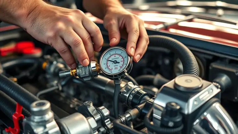
Tools and Safety Precautions for Inspecting the Manifold
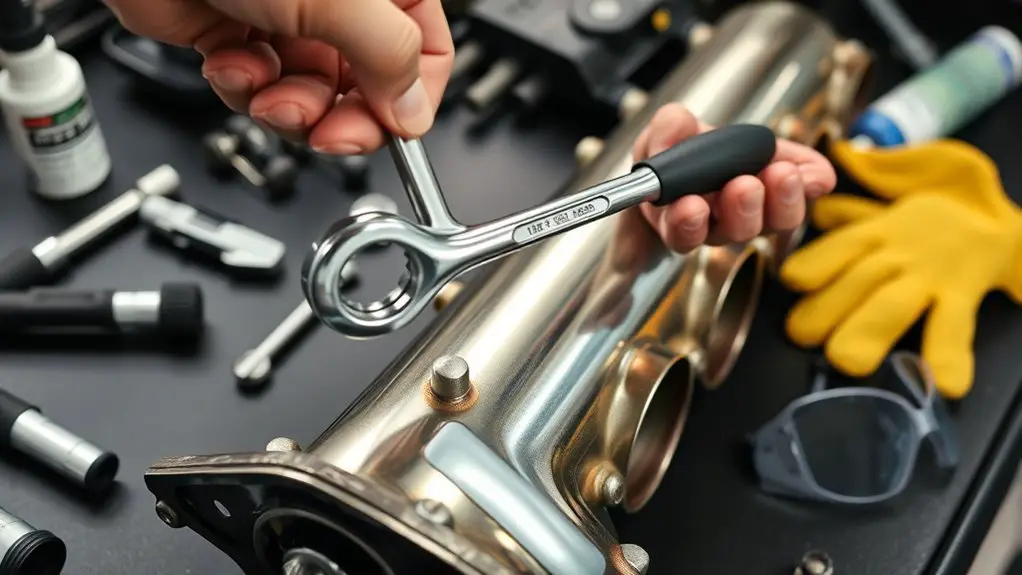
To inspect the exhaust manifold safely and effectively, gather the right tools and follow a strict safety protocol from the start. You’ll use inspection tools like a digital multimeter, compressed-air syringe, mirror, flashlight, and a vacuum gauge to verify connections and flow paths. Dress for containment: safety gear includes gloves, eye protection, and a flame-resistant sleeve or jacket. Disconnect the battery and depressurize the exhaust system before loosening any fasteners. Work in a well-ventilated area; avoid ignition sources near hot components. Use torque specs from the vehicle manual and mark fasteners to track looseness during reassembly. When probing tight areas, keep tools aligned to prevent slip injuries. Check hoses and clamps for fatigue before removal. Maintain a clean workspace, label discarded gaskets, and document measurements for later comparison. Safety gear, inspection tools, and disciplined procedure help you locate defects without unnecessary risk or guesswork.
Visual Signs of a Leaking Exhaust Manifold
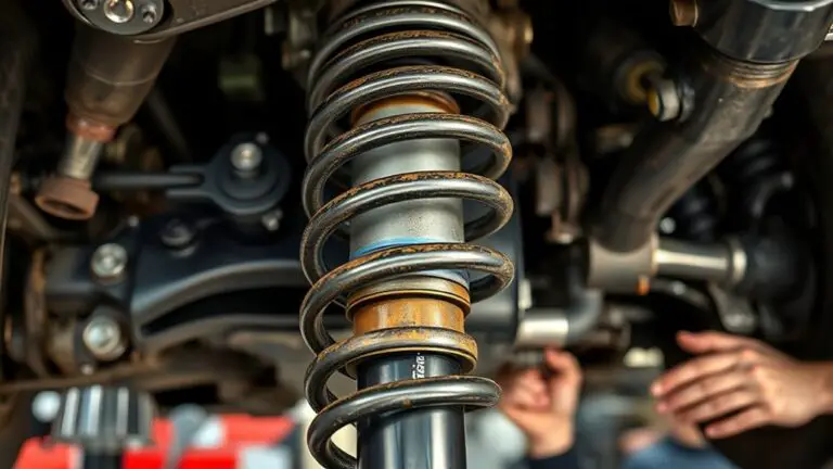
You’ll start by recognizing visual signs such as soot or white-gray deposits around the manifold joints and hardware, plus any fresh blackening indicating active leakage. Look for streaks on surrounding components, erratic heat discoloration, and hissing sounds that correspond to pressure escape. These cues guide you to confirm likely leak sites before proceeding with further inspection steps.
Visual Signs Overview
A visual signs overview focuses on tangible indicators of an exhaust manifold leak you can spot without disassembly. You’ll identify visible flaws and condition cues that pair with engine behavior. Examine the engine bay for thermal staining around exhaust components and mounting points, noting any discoloration or crusty residue. Look for warped or cracked gaskets, loose clamps, and displaced heat shields that reveal gaps. Observe if heat shielding or nearby wiring shows signs of heat exposure or shiny new patches indicating quick fixes. Listen for hissing or tapping when cold starts occur, but reserve verdicts for cross-checking with related symptoms. Document odors and smoke that accompany leakage, yet differentiate from unrelated exhaust leaks. This overview emphasizes visual symptoms as a first-pass assessment of exhaust components.
Leaks Visualization Clues
Visible signs of a leaking exhaust manifold include heat staining, crusty residue, and displaced or damaged gaskets around the manifold joints.
You will inspect for leak detection indicators that point to the exhaust system integrity, focusing on immediate visual and tactile cues. Look for soot shadows at joints, abnormal heat around flanges, and loose fasteners. Listen for faint hissing under load, and note any odor of burning fuel or oil near the manifold. Confirm with a hand-held probe to detect heat contrast along pipes. Monitor exhaust smoke color during idle and throttle changes. Record suspect areas and proceed with controlled pressure or smoke testing if needed to verify leaks.
- Soot deposition patterns at gasket lines
- Unusual heat signatures near flanges
- Cracked or shifted mounting hardware
- Loose or missing gasket fasteners
- Visible exhaust plumes during load changes
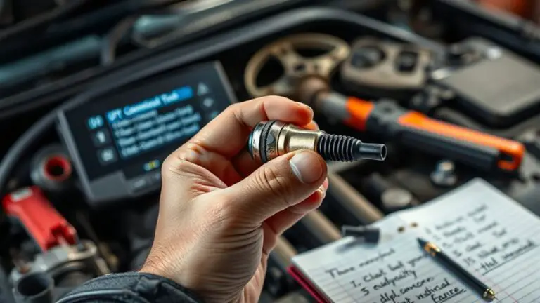
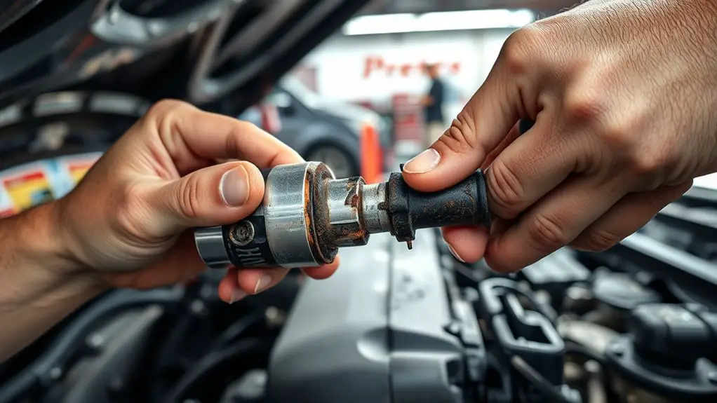
How to Inspect the O2 Sensor Heater for Clogs
How can you reliably determine if the O2 sensor heater is clogged? You’ll perform a focused diagnostic using measured electrical values and trace a path from power to ground. Begin by verifying the heater circuit resistance with a digital multimeter at the sensor terminals, comparing to the OEM specification for your model. A resistance value outside tolerance suggests partial or full clogging effects on heating performance. Next, energize the circuit and observe current draw using the vehicle’s service data or a high-quality ammeter; an abnormally high or low current indicates restricted heater flow or contact issues. Inspect the sensor’s protective sleeve and wiring harness for signs of contamination, pin corrosion, or degraded insulation, since heater clogging causes heat buildup that accelerates damage. If readings deviate but look otherwise intact, consider testing the heater relay or control module output. Document all measurements for cross‑reference with OBD data and O2 sensor functionality trends.
Cleaning or Replacing the O2 Sensor Heater
You’ll inspect the O2 sensor heater for signs of damage or contamination, then decide whether cleaning, replacement, or routing adjustments are needed. Clean the heater element if there’s buildup, replace it if any corrosion or failure is present, and verify the routing path to prevent shorts or stress. Make certain the sensor heater is correctly connected and routed to support reliable heat up without interference with exhaust flow.
Cleaning O2 Heater
If the O2 sensor heater isn’t functioning properly, cleaning or replacing the heater can restore response time and prevent false readings. You’ll pursue a focused cleaning of the heater assembly, targeting deposits that impede current flow and heat transfer. Use non-residua-friendly solvents, precise brushes, and a multimeter to verify continuity after treatment. Maintain strict safety: disconnect power, wear gloves, and work in a well-ventilated area. Document observed resistance changes and listening for consistent electrical noise. Following cleaning methods and heater maintenance practices, reassemble with clean seals and proper torque. Confirm heater heats to specification before road testing. Properly measure post-clean values to guarantee no parasitic draw remains and that sensor signal returns to normal range.
- Confirm insulation integrity and connector cleanliness
- Dry thoroughly before reassembly
- Verify continuity across the heater element
- Inspect for corrosion at mounting points
- Recheck system readings after startup
Replacing Heater Element
Replacing the heater element in the O2 sensor follows directly from cleaning the heater assembly, as degraded element performance often causes slow response or false readings. You’ll verify the sensor’s electrical continuity and insulation, then determine whether the element is replaceable or integrated. If replacement is possible, remove the old element using non-destructive techniques and inspect the housing for corrosion or residue. Choose a compatible heater element type based on your sensor model, ensuring same resistance and wattage characteristics. Install new element using manufacturer-recommended techniques, verify proper seating, and perform a functional check before reinstalling the sensor. Document the installation techniques for future service. After replacement, test for proper heater activation and stable readings, confirming leak conditions are mitigated and performance is restored.
Sensor Heater Routing
Sensor Heater Routing involves inspecting the path and condition of the O2 sensor heater circuit to confirm reliable warm-up and accurate readings. You assess routing for proper clearance, secured connectors, and absence of chafing. If heater wiring shows wear, replace the harness or repair with heat-rated sleeving, then verify continuity and resistance against spec. Confirm that sensor placement minimizes exposure to heat, vibration, and exhaust leaks which can skew diagnostics. Route wires away from hot zones and moving parts, using OEM guides where possible. Reconnect with dielectric grease on pins and test for voltage drop under load before engine start.
- check sensor placement relative to exhaust flow
- inspect heater wiring insulation for cracks
- verify connector integrity and pin resistance
- confirm harness routing won’t contact hot surfaces
- test startup current and cold-warm behavior
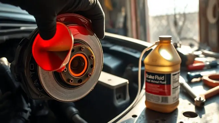
Verifying the Repair and Preventing Future Clogs
After completing the repair, verify the fix by performing a controlled test under conditions that replicate normal engine operation. Begin with a cold start, observe O2 sensor heater activity, and monitor for leaks around the exhaust manifold. Run the engine at idle, then raise to range-typical operating RPMs while watching for abnormal exhaust smells, mounting hissing, or sudden pressure变化. Use diagnostic scan tool data to confirm heater circuit continuity and stable-temperature readings within spec. If readings stay within manufacturer ranges for a full cycle, proceed to a brief engine load test, simulating acceleration and steady-cruise conditions. Record peak temperatures, sensor response times, and any fluctuating values. Conclude with a post-test inspection of the harness, clamps, and sensor port to verify no loosening occurred. Document results for repair verification and note steps taken to mitigate future clog risks. For future prevention, keep the intake area clean and verify that coolant and fuel systems remain free of contaminants.
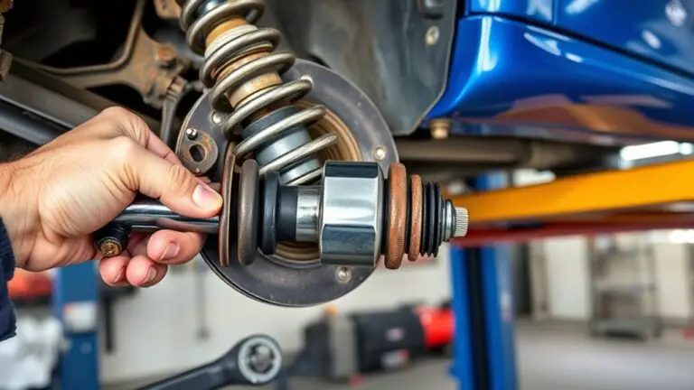
Long-Term Maintenance to Protect Exhaust System Health
To extend exhaust-system life, implement a proactive maintenance routine that targets integrity, cleanliness, and proper operation. You’ll protect exhaust maintenance and system longevity by establishing a schedule, inspecting joints, and validating sensors during routine service. Follow precise steps to detect corrosion, cracks, and leaks early, then act with approved repair methods. Maintain fuel and oil cleanliness to reduce deposits; use quality gaskets and hardware to preserve seal integrity. Track miles and time to anticipate component fatigue, replacing worn parts before failure. Document findings to guide future interventions and performance trends.
- Inspect hangers, mounts, and clamps for tightness and corrosion every 6,000–8,000 miles.
- Measure exhaust backpressure and look for abnormal variations during diagnostics.
- Clean flanges and mating surfaces, applying anti-seize where appropriate.
- Verify O2 sensor heater operation after any exhaust-service work.
- Schedule preventive replacements aligned with OEM intervals to sustain exhaust maintenance and system longevity.
Frequently Asked Questions
Can O2 Sensor Heater Clogging Cause MPG Drops?
A quick fact: O2 sensor failures or slow heating can cut fuel efficiency by up to 15% in some cases. Yes, O2 sensor heater clogging can cause mpg drops by delaying sensor readouts, triggering incorrect fuel trims. You’ll notice richer or leaner mixtures as you drive. Inspect the sensor, heater circuit, and wiring, then clean or replace as needed. Make sure proper exhaust leaks are sealed, and test with a fuel efficiency monitor to quantify improvement.
Will a Faulty Heater Affect Catalytic Converter Efficiency?
Yes, a faulty heater can reduce catalytic converter efficiency. When the O2 sensor heater malfunctions, exhaust gas readings become skewed, potentially causing the engine to run rich or lean and degrade emission standards compliance. You’ll notice higher emissions, possible fault codes, and reduced converter performance. To protect catalytic converter function, diagnose heater impedance and wiring, replace a faulty sensor, and verify proper downstream trim. Maintain compliance with emission standards by ensuring accurate sensor operation and stable exhaust mixture.
Can Exhaust Leaks Affect O2 Sensor Readings?
Yes, exhaust leaks can affect O2 sensor readings. When you have an exhaust leak, the pressure dynamics change upstream and downstream, altering sensor signals and causing sensor malfunction. You’ll notice erratic voltage, delayed response, or fluctuating fuel trims. Inspect for cracked manifolds or gaskets, repair promptly, and retest. Monitor exhaust pressure after repair to confirm stable readings and restore accurate sensor data for proper engine control.
Are Bypassed or Removed Sensors Legal or Safe?
Yes, bypassed or removed sensors are generally illegal and unsafe. Sensor legality depends on emissions regulations in your jurisdiction, and tampering can violate those rules. You’ll fail inspections, risk liability, and potentially impair engine management. If you’re pursuing freedom, pursue compliant fixes: repair or replace faulty sensors, clear obstructions, and restore proper heater function. Follow OEM procedures, use approved parts, and document maintenance to meet emissions regulations while preserving safe, reliable operation.
How Long Do O2 Sensor Heaters Typically Last?
O2 sensor heaters typically last about 60,000 to 100,000 miles, depending on engine temperature cycling and electrical load. You should monitor O2 sensor maintenance regularly, watch for sluggish heater warmups, and replace sensors if readings drift. Expect shorter life under hard acceleration, high mileage, or extended cold starts. Use proper torque and anti-seize when installing. Maintain clean exhaust ports and avoid contamination to maximize O2 sensor lifespan.