How to Test and Tune After Installing Body Lift to Avoid Leaks After Gasket Upgrade
After you install a body lift and upgrade the gasket, you’ll start with a controlled pressure test and torque verification. Verify all fasteners are torqued to spec in the proper sequence, then gradually pressurize your cooling system while watching for leaks at gasket interfaces, hoses, and fittings. Bleed air from the highest point, reseal, and recheck after a run. Document deviations and run a follow‑up retorque; more specifics await if you keep going.
Pressure Testing Fundamentals After a Gasket Upgrade
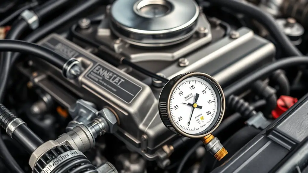
Before performing any pressure test, guarantee the system is fully assembled, all fasteners are torqued to spec, and any safety devices are in place. You’ll approach pressure testing with strict discipline: verify the coolant, fuel, or air lines are routed correctly, all seals replaced, and the gasket seat clean. Establish a controlled test environment, using appropriate pressure ranges for your system, and document target values before energizing. Incremental pressurization minimizes shock loads; monitor gauges, relief valves, and sensor readings continuously. Observe for leaks at gasket interfaces, fittings, and flanges, noting any drift in pressure that could indicate gasket integrity issues. If a leak appears, depressurize safely, inspect the gasket seating, and re-torque faster loosening points after reassembly. Maintain consistent test durations to distinguish transient seals from persistent leaks. Conclude with a final pressure hold, compare results to expected benchmarks, and record outcomes to inform subsequent tuning and long-term reliability.
Safe Setup and Precautions for Lifted Vehicle Testing
You start with Safe Pre-test Checks to confirm tools, jacks, and stands are rated for the lift and positioned on solid ground. Then perform Leak Detection Steps to verify seals, hose connections, and fluid lines before load testing, documenting any anomalies. Finally, follow Ride Test Protocols that outline gradual load, steering, braking, and suspension observations to guide further adjustments.
Safe Pre-test Checks
Safe pre-test checks begin with a systematic setup that minimizes risk and guarantees repeatable results. You verify overall vehicle readiness before any pressure test: secure the work area, chock wheels, and ascertain the lift remains stable. Inspect fender clearance and body-to-frame gaps to confirm consistent alignment, then confirm fasteners are torqued per specification. Review extensions of hoses and wiring for proper routing, avoiding pinch points during articulation. Consider body lift considerations for airflow and clearance under the hood, and confirm gasket compatibility between upgraded components and existing seals. Remove ignition keys, lockout energy sources, and establish a clear, standby communication plan with helpers. Document baseline measurements and any deviations, then proceed to controlled, incremental testing with a pre-defined failure protocol.
Leak Detection Steps
When testing a lifted vehicle, start by establishing a controlled, low-risk environment and verifying all safety measures are in place: secure the area, stabilize the lift, and confirm fender clearance, body-to-frame gaps, and fastener torque per spec. You then identify potential leak sources by inspecting gasket interfaces, hose fittings, and coolant passages before pressurization. Use a systematic approach to apply pressure gradually, monitoring all joints with a flashlight and mirror, and listen for hisses at seals. For detection methods, employ tracer dye or UV dye to reveal slow seepage, and pair with infrared thermography for temperature anomalies near gaskets. Document every finding, isolate suspect joints, and retest after adjustments. Maintain clarity, avoid distraction, and guarantee immediate shutdown if unsafe conditions arise.
Ride Test Protocols
After confirming leak-free, properly pressurized conditions from the prior steps, proceed with a controlled ride test that prioritizes stability, clearance, and repeatable data collection. You’ll evaluate ride comfort and handling stability across surfaces, noting deviations, vibrations, and chassis squat. Use a structured approach: accelerate, decelerate, and corner at incremental speeds while logging suspension travel, tire contact, and body roll. Maintain a steady pace to avoid thermal or tire wear artifacts, and stop to inspect fasteners, mounting points, and underbody clearances. Table emphasizes a key point below.
| Parameter | Ideal Range | Observation |
|---|---|---|
| Ride height | ±1 inch | Record pre/post elevations |
| Vibration | Low | Note frequency/none |
| Turn-in | Predictable | Capture data |
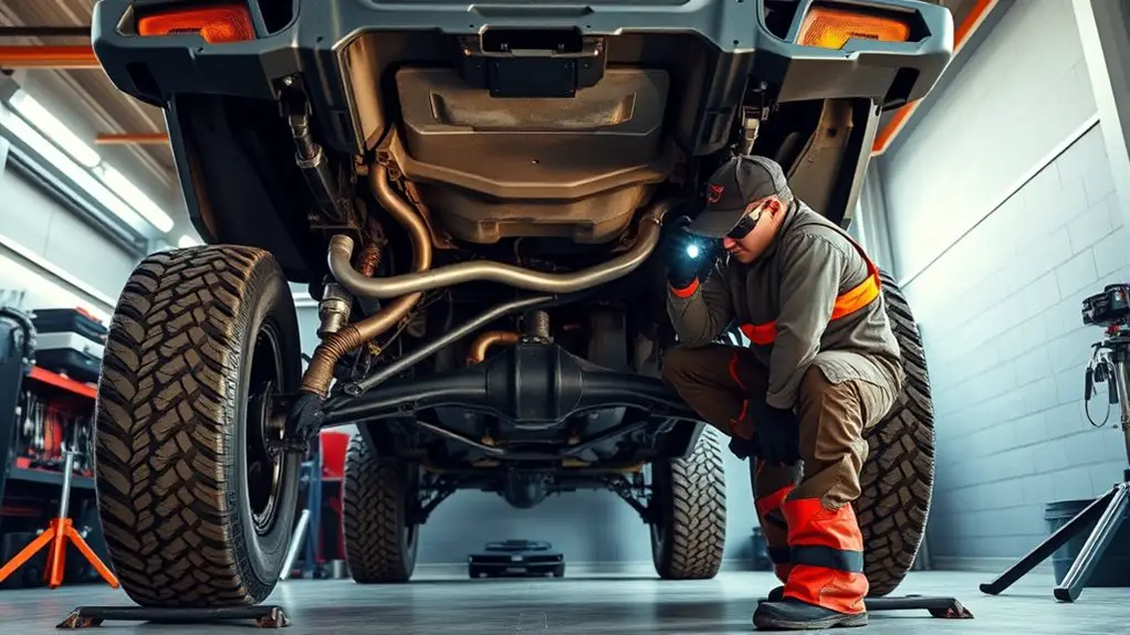
Inspecting for Common Leak Points in a Lifted Vehicle
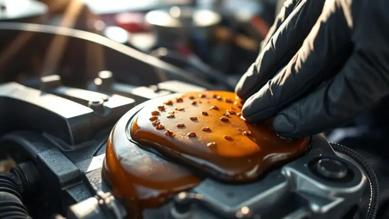
You should start by inspecting visible seal areas for signs of wear or misalignment, noting any gaps or hardened seals that could leak under load. Look for drips and dribbles at joints, fittings, and drainage points, and confirm if any moisture path correlates with recent mounting or torque changes. Establish a baseline by documenting exact locations, then plan targeted checks during subsequent tests to verify integrity.
Visible Seal Areas
Visible seal areas are where leaks most often originate after a body lift, so start by systematically inspecting joints, seams, and gaskets at the transfer case, transmission, engine oil pan, and coolant passages. You’ll methodically trace each potential seam, noting any misalignment, gaps, or lingering residue. Focus on gasket continuity, fastener torque, and surface flatness, documenting findings with a clean color mark and a magnified view where needed. This phase centers on visible seal maintenance and gasket integrity inspection, ensuring each interface presents a uniform seal surface before pressure testing. Prioritize disassembly only where necessary to verify mating surfaces; otherwise, use noninvasive sealing checks. Record outcomes, flag suspect components, and proceed to corrective steps with repeatable, measured procedures.
Drips and Dribbles Check
Building on the prior seal inspection, you’ll shift focus to drips and dribbles as the next recognizing point for leaks after a body lift. In this step, you methodically track any moisture near gasket seams, flank lines, and transfer points while the vehicle rests and after short engine heat cycles. Sleep on every suspected spot: note size, location, and timing of a drip, spill, or bead. Use a clean, dry background and controlled fluids to avoid false positives, then document with markers and photos. Perform drip detection during a deliberate warm-up, then monitor fluid monitoring indicators over a defined interval to confirm persistence. If drips appear, isolate the source, re-check seals, and re-test under the same conditions before proceeding.
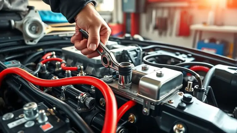
Bolt Torque Verification and Re-Torque Protocols
Bolt torque verification and re-torque protocols are essential to confirm fastener integrity after body lift installations. You’ll follow a precise plan to validate all fasteners meet spec, then re-check after a short run. Begin with bolt alignment checks to confirm each stud seats correctly and threads engage cleanly. Use the manufacturer’s torque sequence order, typically crisscross or spiral patterns, to minimize distortion and uneven loading. Torque in gradual steps, pausing to inspect gaskets and paint marks for movement. After the initial torque, perform a controlled run cycle and re-torque at the specified interval, commonly 3–6 hours or 100 miles, depending on conditions. Document readings, torque values, and any deviations. If a fastener shows movement, re-clean threads and re-torque to spec before proceeding.
| Step | Action | Verification |
|---|---|---|
| 1 | Inspect bolt alignment | Visual and seating check |
| 2 | Apply torque sequence | Confirm pattern adherence |
| 3 | Wait and re-torque | Interval value recorded |
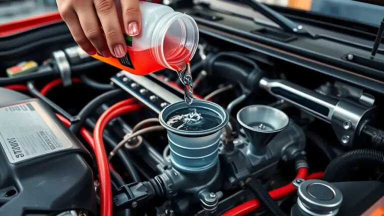
Coolant System Verification and Air Bleed Procedures
Coolant system verification begins with confirming that all hoses, clamps, and fittings are properly connected and free of leaks before any fill. You proceed by inspecting the radiator, heater core, and bypass lines for signs of strain or distortion, replacing any compromised components. Next, you fill with the correct coolant mix to the specified reservoir level, avoiding overfill that could mask leaks. Once filled, you bleed the system to purge air pockets, starting at the highest point and working toward the engine. Maintain steady, deliberate pressure on the recovery tank while monitoring the hose circulation and cap seal. Observe coolant flow as it circulates, noting any sudden temperature spikes or stalled movement that indicate blockages. After initial bleed, run the engine to operating temperature with the cap loose, then reseal after a controlled cooldown. Verify restored coolant flow and absence of air pockets under normal operating conditions, documenting results for future maintenance.
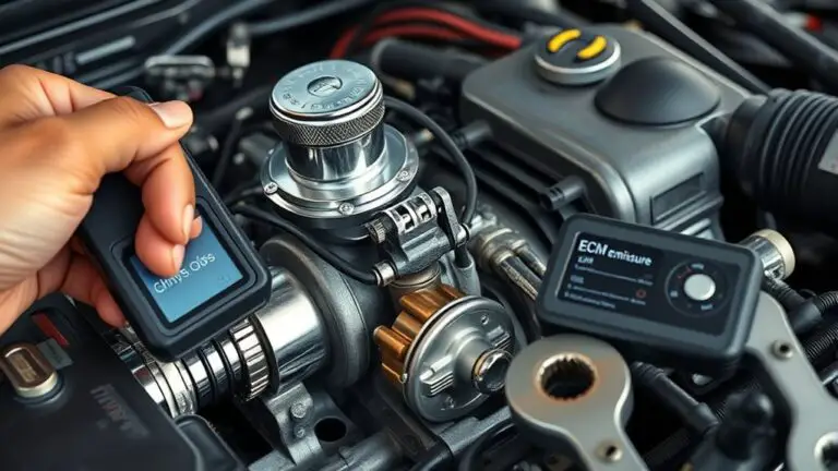
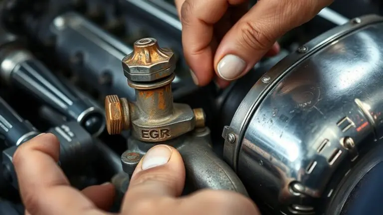
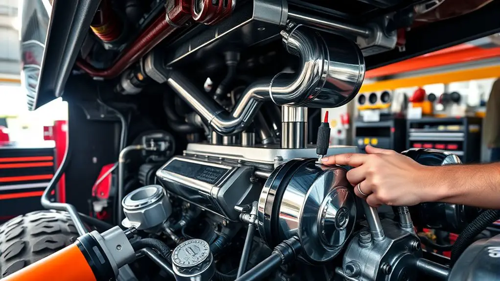
Vacuum System Checks and Dialing in Vacuum Signals
With the coolant system verified and bled, you’re ready to assess the vacuum system and dial in the vacuum signals. Begin with a clean baseline: confirm all fittings are tight, hoses routed without sharp bends, and the intake manifold ports sealed. Measure baseline vacuum with the engine at idle and after a fast idle to establish a reference. Monitor for steady, stable signals; any fluctuation indicates a pulling path or a subtle leak. Conduct a controlled pressure hold test on the booster, lines, and check valves, noting any drop over time. Use a diagnostic vacuum gauge or an equivalent scanner to track signal monitoring across RPM ranges, documenting peak and idle values. Identify and address vacuum leaks promptly, prioritizing crimped fittings and degraded diaphragms. Re-test after each adjustment, ensuring repeatable results and consistent vacuum under load. Precision and repeatability protect the gasket upgrade and align performance with your freedom-driven goals.
Fluid Diagnostics: Identifying Contaminants and Leaks
Fluid diagnostics begin by establishing a clean baseline for all fluid systems and then systematically identifying contaminants and leaks. You’ll map current fluid types across systems, noting viscosity, color, and odor as baseline indicators. Next, isolate contamination sources by tracing lines, seals, and reservoirs to their origins, recording each discrepancy with time stamps and measurements. Use a calibrated checklist to differentiate particulates, moisture, and oil ingress from fuel or coolant streams. Employ simple tests: flow-rate comparisons under load, pressure decay, and temperature differentials to reveal slow leaks or micro-cracks. Document contamination events, correlating them with service history and gasket upgrades. Prioritize headroom for future maintenance by classifying findings as actionable vs. informational. Maintain a strict hygiene protocol to prevent cross-contamination during inspection. Finally, synthesize results into a concise diagnostic map that guides corrective actions, ensuring you preserve system integrity while preserving the freedom to tune and test without ambiguity.
Tuning Adjustments to Minimize Leaks and Optimize Performance
Tuning adjustments to minimize leaks and optimize performance require a disciplined, data-driven approach: identify root causes, apply targeted iterations, and verify results under representative load conditions. You’ll methodically log gasket materials behavior across temp and pressure ranges, isolating variables to prevent confounding effects. Begin with baseline measurements after the intake and exhaust are re-sealed, then introduce controlled load profiles to reveal transient leaks. Deploy incremental tightness changes and material interfaces, documenting each delta with torque values, gasket seating conditions, and bolt sequence notes. Prioritize repeatability: replicate tests under similar ambient conditions to distinguish genuine performance enhancements from noise. Compare seal integrity, flow resistance, and temperature gradients to predefined acceptance criteria. Use this data to select gasket materials that balance compatibility, durability, and sealing force. Conclude with a concise maintenance plan, highlighting monitoring intervals and signs warranting re-torque or material revision for sustained performance enhancements.
Frequently Asked Questions
How Often Should I Recheck Gasket Seals After a Lift Installation?
You should recheck gasket seals every 2–4 weeks during the first few months after a lift installation. Then shift to monthly or after any hard crossings, heavy vibrations, or temperature swings. Prioritize gasket maintenance and leak prevention by inspecting all joins, bolts, and seals with a torque wrench, noting inconsistencies. Document checks, re-torque as needed, and test for pressure loss. Stay methodical, precise, and proactive to maintain freedom and reliability.
Which Tools Best Detect Slow Coolant Leaks Post-Upgrade?
Within a real-world case, you’d use a coolant dye and a pressure tester to pinpoint slow leaks after an upgrade. You start by pressurizing the system to a specified value, then introduce coolant dye and observe for color migration at seams, hoses, and the radiator. Record findings, repeat at intervals, and verify with a second diagnostic run. Prioritize a controlled environment, steady pressure, and precise readings to avoid misdiagnoses.
Can Gravity Bleeding Replace a Pump-Driven Bleed in a Lifted Setup?
Yes, gravity bleeding can substitute for a pump-driven bleed in a lifted setup, but with caveats. Gravity bleeding benefits include simplicity and fewer mechanical shocks, yet it’s slower and relies on engine orientation and coolant flow. Compare it to a pump-driven method, which offers faster, more controllable air removal. You’ll aim for a steady, uninterrupted flow, monitor for steps, and choose the method that preserves consistent coolant pockets while respecting the gravity-driven limits.
Do Vacuum Lines Require Different Routing After a Lift?
Vacuum lines can require adjusted routing after a lift. You should inspect clearances, avoid rubbing, and reroute to maintain consistent manifold vacuum and intake tract integrity. Confirm vacuum source proximity to engine bay and prevent sharp bends. Measure line lengths for uniformity and map them to new engine heights. Implement lift adjustments by relocating lines away from moving components and heat zones. Recheck with a vacuum test, ensuring steady readings and no leaks.
What Signs Indicate Hidden Leaks Beyond Visible Drips?
Hidden leaks show as steady, low-volume seepage, faint odors, or moisture tracing beyond obvious drips; they may appear only after pressure tests or temperature changes. For leak detection, monitor all connections during idle and under load, check manifolds, gaskets, and seals with soapy solutions, and verify vacuum lines are tight. Use a pressure ramp and recording over time to catch slow escapes. Stay systematic, document findings, and pursue precise fixes to preserve performance and safety.