How to Test Fuel Pressure With a Multimeter
To test fuel pressure with a multimeter, start by ensuring safety: power off, depressurize, and inspect for damaged wiring. Locate the fuel pump relay, fuse, and wiring harness, then verify ground integrity. Use the multimeter to measure voltage at the pump while the system is active, noting any drops from battery voltage during cranking or running. Check resistance in related sensors and continuity in the feed and ground circuits. If readings drift, you’re closer to the fault, and more checks follow.
Safety First: Handling Electrical Tests Around Fuel Systems
When testing around fuel systems, always prioritize safety: electricity and flammable vapors are a dangerous combination. You approach every probe with deliberate focus, minimizing ignition sources and confirming proper ventilation. Before you connect a multimeter, verify the vehicle is powered down, the key is out, and capacitors are discharged where applicable. Inspect wiring for damaged insulation, exposed conductors, and corroded connectors; replace compromised components to maintain fuel system integrity and electrical safety. Use insulated tools, keep sparks away, and avoid creating static discharge near the fuel line. Post-test, recheck for residual fuel vapors and secure all panels, covers, and shielding. Document any deviations from normal readings and suspend testing if you detect abnormal heat, odor, or smoke. Maintain a clean, organized workspace, label circuits clearly, and follow the vehicle manufacturer’s electrical safety guidance. Your discipline protects you, your vehicle, and the fuel system from preventable hazards.
Tools You’ll Need for Fuel Pump Circuit Diagnostics
You’ll need a concise set of testing tools to accurately diagnose the fuel pump circuit. Start with essential testing tools, then apply circuit diagnostic tips to interpret readings, all while adhering to safety considerations. This section sets the framework for precise, repeatable measurements that inform your fuel pressure testing workflow.
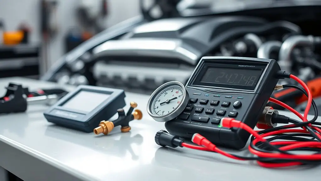
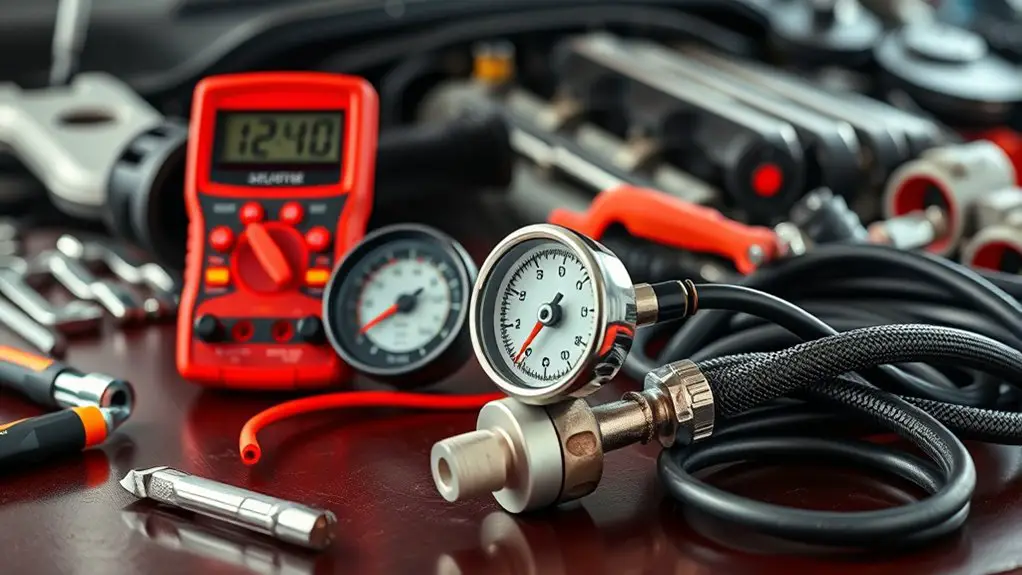
Essential Testing Tools
To diagnose the fuel pump circuit effectively, you’ll need a core set of tools: a digital multimeter, fuel pressure gauge, safety gear, and basic hand tools.
- Digital multimeter with fresh batteries and proper leads
- Fuel pressure gauge and adapters compatible with your system
- Personal protective equipment: gloves, eye protection, face shield when venting
- Diagnostic wiring and quick-clip probes for secure test points
- Basic hand tools: screwdrivers, pliers, wrenches, and a flashlight for visibility
Having these on hand guarantees precise fuel pressure measurements and clean multimeter usage. Stay organized, label connectors, and follow manufacturer specs. This toolkit supports methodical checks, reduces guesswork, and preserves your freedom to troubleshoot confidently without unnecessary detours.
Circuit Diagnostic Tips
Circuit diagnostic tips begin with the right toolkit, so assemble a focused set: a digital multimeter, a fuel pressure gauge with compatible adapters, protective gear, and secure test leads. You’ll need to verify circuit continuity first, confirming paths are complete before applying any load. Use the multimeter in resistance or continuity mode to trace wiring, connectors, and relays, isolating faults without energizing the system. When diagnosing, monitor voltage drop under load to identify parasitic resistance that reduces fuel pump current. Document baseline measurements for engine-off and running states, then compare against expected values from your vehicle’s schematic. Keep test points clean and insulated, minimize lead length, and label each path. Precision in connections prevents stray readings and accelerates fault localization.
Safety Considerations
Safety first is mandatory when diagnosing fuel pump circuits, so assemble the right tools with proper PPE and secure work practices before you start. You’ll need a calm, measured approach to minimize risk while testing with a multimeter. Adhere to fuel system hazards awareness and follow electrical safety precautions to protect yourself and the vehicle. Equipment selection should prioritize non-sparking tools, insulated gloves, eye protection, and a fire-safe workspace. Isolate the battery, relieve fuel pressure, and verify ground continuity before probing any connections. Keep a fire extinguisher nearby and avoid open flames. Document test points and readings for traceability and repeatability.
- PPE and protective gear
- Insulation and grip-tested tools
- Battery isolation steps
- Fuel pressure relief procedure
- Safe testing protocol and documentation
Understanding Basic Multimeter Functions for This Task
You’ll start by clarifying Multimeter Basics, focusing on selecting the right range and pins for fuel system work. Use Voltage Measurement Tips to verify signals safely, keeping probes stable and readings steady while documenting results. For Safety and Setup, configure the meter to appropriate modes, check batteries and fuses, and establish a clean, noncontact path to avoid shorts.
Multimeter Basics
To work with a multimeter for fuel-pressure testing, you first must understand its basic functions and how they apply to automotive measurements. You’ll focus on accuracy, range, and safety, not fluff. Below are core concepts you’ll rely on:
- multimeter types and their input impedance, plus which mode suits voltage, resistance, and continuity
- primary multimeter features: display, probes, fuse protection, and auto-range vs manual-range
- measurement technique: proper contact, zero checks, and reading stability
- safety practices: disconnect power when probing, and avoid backfeed during tests
- interpretation approach: compare to spec values and note drift or anomalies
These basics empower precise readings and confident troubleshooting.
Voltage Measurement Tips
Voltage measurement begins with selecting the correct meter range and probe configuration, then verifying the ground reference is solid and the test point is accessible. You’ll confirm your meter is set to DC voltage, calibrated, and capable of handling the expected range. Attach probes with clean, secure contact; avoid accidental shorts by keeping leads clear of moving parts. When measuring, observe the voltage drop across a specific point or component to infer circuit health, not just the absolute value. Record multiple readings to assess stability, and note any fluctuation that could signal load variance. Maintain tight probe contact, minimize probe movement, and respect polarity. Accurate results depend on stable grounding and consistent technique, contributing to improved measurement accuracy and reliable fuel-pressure diagnostics.
Safety and Setup
Safety and Setup: Before you start testing fuel pressure, verify you know how your multimeter functions and how to apply them safely. You’ll establish clear safety protocols and confirm your understanding of the fuel system’s risks. Prepare, then proceed with measured steps to reduce error and danger. Use proper settings, correct leads, and a known-good reference. Maintain a clean, stable work area and disconnect nonessential power when possible. Verify battery strength, fuse integrity, and tool condition before contact. Follow procedural checks to prevent arcing or short circuits. Document readings and conditions for traceability. Practice consistent grounding, isolation, and secure connections to avoid leaks, sprays, or ignition sources.
- Understand multimeter functions and ranges
- Confirm correct leads and probes
- Verify safety protocols and ventilation
- Secure the fuel system and surrounding area
- Record conditions and results for review
Locating the Fuel Pump Relay, Fuse, and Wiring Harness
Locating the fuel pump relay, fuse, and wiring harness is a precise, step-by-step task. You’ll identify the correct relay, fuse, and harness routes to power the pump without guesswork. Begin with the vehicle’s diagram or fuse box cover to confirm the fuel pump location and the corresponding relay label. Then, locate the relay in the under-hood fuse/relay block or under the dash panel, using the diagram for relay identification. Check for a dedicated fuel pump fuse and a relay with two or more identical terminals, ensuring you’re examining the correct circuit. Trace the wiring from the pump to the harness bundle, noting connector types and color codes. Disconnect only when necessary and with the ignition off. Inspect terminals for corrosion, secure fit, and continuity, and reseat components firmly. Document findings for later testing, and proceed to the measurement phase with confidence and clarity.
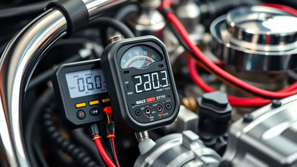
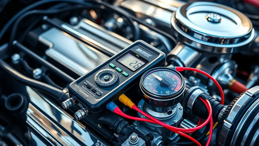
Measuring Voltage Across the Fuel Pump Circuit
To measure voltage across the fuel pump circuit, connect a reliable digital multimeter in parallel with the pump’s power supply line and ground. You’re evaluating fuel pump operation by watching real-time voltage and locating any voltage drop that would impair operation. Keep leads secure and minimize contact resistance to avoid skewed readings. Use a low-load setting if available to reduce circuit interference, and record the steady-state voltage during cranking and run.
- Verify ground integrity and harness continuity before measuring
- Compare pump voltage to battery voltage under cranking vs. running
- Note any sudden dips that align with suspected fuel cutting events
- Document the duration and magnitude of voltage drop for diagnosis
- Cross-check with fwd supply when the relay is energized
Interpreting results: consistent voltage within spec confirms proper pump operation; persistent voltage drop points to harness, relay, or ground issues affecting performance.
Checking Resistance in Sensors Related to Fuel Delivery
Next, you’ll assess resistance values in sensors tied to fuel delivery to confirm they’re within specification. You’ll set up your multimeter in resistance mode and identify relevant pins on the fuel system connectors. Begin with the fuel injector resistance, ensuring each injector coil reads within the manufacturer’s specified range; compare cold and hot measurements if the spec allows. Note that deviations can indicate internal winding issues or mismatched injectors. Then test the fuel pressure sensor circuit by measuring its sensor resistance at the connector and reference ground, following the vehicle’s wiring diagram to locate the correct terminals. Record steady, incremental changes only when wiggling or applying light pressure to connectors, which can reveal intermittent faults. Maintain a clean, dry inspection area and avoid introducing contamination. If readings fall outside spec, plan targeted diagnostic steps or component replacement, staying mindful that resolution hinges on repeatable, verifiable resistance values rather than single measurements.
Interpreting Readings: What Numbers Indicate a Fault
Interpreting readings requires a careful, rule-based approach: compare each value to the manufacturer’s spec for the component and note whether it lies within, at, or beyond tolerance.
You’ll translate numbers into conclusions by measuring against normal ranges and spotting deviations that indicate faulty readings. Focus on consistency across tests, not a single spike. When a value sits outside the expected band, mark it as a potential fault and investigate contributing factors before drawing a final conclusion.
- Compare to normal ranges and note any outliers
- Distinguish between transient fluctuation and sustained deviation
- Flag values that sit at the edge of tolerance for recheck
- Correlate readings with operating conditions (temperature, rpm)
- Document each result clearly for traceability
If multiple readings consistently fall outside normal ranges, you likely have a fault; if they cluster around the spec, readings are normal. Use disciplined judgment, not guesswork.
Common Wiring Faults That Mimic Fuel Delivery Problems
Wiring faults can masquerade as fuel delivery problems, so you should start by validating the electrical side before chasing mechanical causes. You’ll inspect power and ground circuits for consistent voltage, resistance, and proper grounding under load. Look for wiring shorts by tracing harness routes and testing for accidental contact with hot surfaces or metal edges; subtle shorts can produce intermittent fuel pressure readings. Check relay operation and fuse integrity, since a failing relay may mimic low pressure by cutting power to the pump on demand, not continuous duty. Connector corrosion deserves scrutiny: oxidized terminals increase contact resistance, causing voltage drops that mimic fuel starvation. Disconnect harnesses to inspect for greenish or white crust, bent pins, and loose fits, replacing any degraded connector or pin as a single, calibrated step. Validate that channel impedance remains within spec during cycling, and confirm that the ECU references the correct ground. Only after clean, stable electricals should you pursue mechanical diagnoses.
Step-by-Step Troubleshooting Flow for Quick Diagnosis
To diagnose efficiently, follow a structured, step-by-step flow that validates electricals first, then narrows to mechanical causes. You’ll anchor the process in repeatable checks you can trust, with clear criteria at each stage. Begin with simple electrical verification, then proceed to targeted measurements of fuel pressure and related signals via multimeter usage. If readings are out of spec, correct wiring or sensor faults before testing other components. When electricals check out, shift to mechanical fault isolation, using controlled tests and documentation.
- Verify battery health and starter circuit integrity before fuel-related tests
- Check fuel pump relay and wiring continuity with a multimeter usage approach
- Measure fuel pressure at the rail and compare to spec
- Inspect pressure regulator, filters, and return lines for restrictions
- Confirm sensor signals (MAP/PSI) correlate with engine load and RPM
Document results, repeat any critical tests, and proceed only with confirmed deviations.
Frequently Asked Questions
Can a Multimeter Be Used to Test Fuel Pressure Directly?
Yes, you can’t directly test fuel pressure with a multimeter. A real-world note: a mechanic once traced a faulty fuel rail sensor with a multimeter, then confirmed pressure with a dedicated gauge. You’d use fuel pressure gauges to measure actual pressure, while a multimeter’s limitations show up in electrical diagnostics rather than pressure values. So rely on gauges for pressure; use the meter for circuits, connections, and sensor signals within its limitations.
What Meter Settings Are Safest Near High-Pressure Fuel Lines?
The safest answer: don’t use any meter settings near high-pressure fuel lines. Avoid electrical testing on live systems; instead, rely on proper safety precautions and a dedicated pressure gauge. When you measure, set up with the engine off, relieve pressure, and connect the gauge securely. Use only the manufacturer’s reference ranges, zero leaks, and monitor readings calmly. Respect pressure limits, isolate circuits, and keep ignition off until you’ve completed the safety checks.
Should I Disconnect the Battery Before Any Test Procedure?
Yes, you should disconnect the battery before any test procedure. About 12–15% of automotive fires involve electrical shorts during maintenance, so battery safety matters. For test preparation, remove the negative terminal first, then the positive, and confirm tools don’t bridge circuits. Reconnect only after measurements, and verify the system is de-energized. Keep your methodical approach, check for residual charge, and work in a dry, ventilated area to maintain safe, precise testing.
How Do I Verify You’Ve Measured the Correct Fuel Pump Ground?
To verify you’ve measured the correct fuel pump ground, test ground continuity first and confirm a solid direct path to chassis. Then measure voltage drop under load between the pump ground and battery negative; it should be near zero, ideally below 0.1 volts. If you see higher drop, clean connectors, reseat ground straps, and recheck. A low ground continuity value and minimal voltage drop indicate you’ve got the right fuel pump ground.
Can Ambient Temperature Affect Fuel Pressure Readings?
Ambient temperature can affect fuel pressure readings. Temperature shifts alter fuel viscosity and sensor response, causing ambient temperature impact to create subtle fuel pressure variations. You’ll notice higher temps tend to lower density and pressure readings, while colder conditions can stiffen fuel and raise readings. So, account for ambient temperature, stabilize engine heat, and compare measurements at similar temperatures. You should document the conditions, repeat tests, and correlate variations with known temperature ranges for precise results.