How to Test USB Port With a Panel Clips
To test a USB port with panel clips, start by gathering a multimeter, a known-good USB cable, the device under test, and a clean power source, then power down equipment and inspect all cables for wear. Align the USB port with the panel clips, ensuring proper seating and strain relief, and verify mating surfaces are flat. Ground the tester and check continuity, signal lines (D+, D−), and voltage stability across cycles; you’ll spot misalignment, corrosion, or poor contact. If you keep going, you’ll uncover more detailed steps and tips.
Preparing Your Tools and Safety Precautions

To begin, gather these essentials: a multimeter (or USB current/voltage tester), a known-good USB cable, the device under test, and a computer or power source. You’ll perform a controlled setup, so choose tool selection that matches the test you plan, minimizing impedance and measurement error. Inspect cables for wear, and designate a clean work area with stable grounding. Put on safety gear: eye protection, and gloves if you’ll handle live connectors. Power down equipment before connections, then verify hemostatic joins are clean and dry. Connect the known-good cable to the device and your tester, ensuring proper orientation. Use the multimeter to monitor voltage, current, and continuity as you enable power. Document readings with timestamps and compare against expected USB specs. Maintain a methodical workflow: confirm each step before advancing, isolate the device if abnormal readings appear, and store tools in a designated kit to preserve calibration. This disciplined approach supports reliable results and freedom to troubleshoot.
Understanding Panel Clips and USB Port Basics

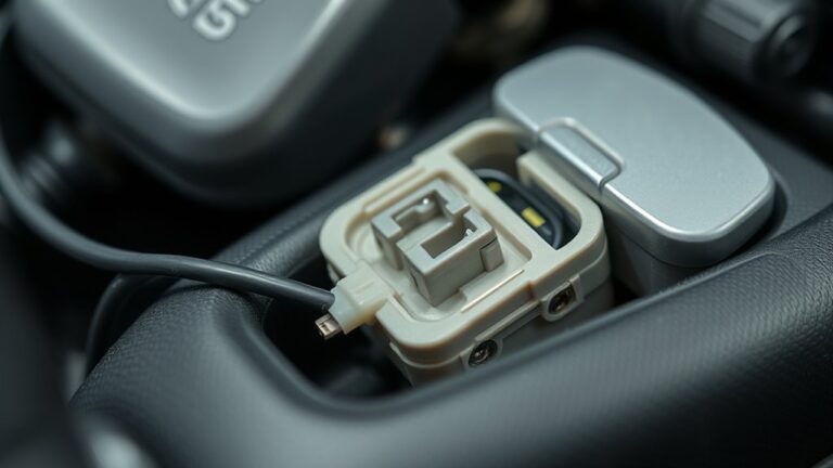
Panel clips secure the USB port housing and must be inspected for proper engagement. You’ll review basic USB port design, common connector types, and how clips interact with the panel to maintain alignment. Then you’ll apply clip-testing techniques to verify stability and identify any seating or retention issues.
Panel Clips Overview
Panel clips are small fasteners that secure a USB port or panel to a chassis, ensuring alignment and stability. You’ll approach this with exacting clarity, outlining what makes panel clips functional without delving into USB port basics. Consider panel clip materials: how material choice affects rigidity, thermal tolerance, and corrosion resistance in typical chassis environments. Next, examine clip design variations: differing tangs, detents, and retention forces that influence ease of installation and serviceability. Evaluate mating surfaces for flatness, groove alignment, and stress distribution to prevent distortion during panel reassembly. Document installation steps to verify proper seating, then test for positional repeatability across cycles. Maintain a concise, procedural tone so the process remains transparent, repeatable, and adaptable to varied chassis geometries and user preferences for freedom in method.
USB Port Basics
USB ports provide a fixed, standardized interface for data and power transfer, and understanding their basics helps guarantee reliable connection and serviceability. You’ll encounter common USB port types (Type-A, Type-B, Micro/Micro-B, USB-C), each with distinct shapes, roles, and mating requirements. Knowing how pins map to signals clarifies compatibility and troubleshooting pathways. USB power standards define voltage, current, and charging profiles, influencing device behavior and cable quality expectations. As you plan panel clips tests, distinguish hosts, peripherals, and charging devices to prevent misinterpretation of results. Consider polarity, cable gauge, and secure mechanical fit to minimize contact resistance. By aligning port type recognition with power specification awareness, you preserve safety, secure consistent measurements, and support future upgrades without rewiring.
Clip-Testing Techniques
To test connections reliably, you’ll start by verifying how panel clips interact with USB port interfaces and how clip geometry affects contact force and alignment. In clip-testing techniques, observe contact consistency across repeated cycles, noting any drift in position or pressure. Evaluate clip application: ascertain clips seating surfaces match port chamfers and pin arrays, avoiding side loads that distort USB wells. Check retention force against insertion/removal cycles to prevent intermittent connectivity without overstressing the PCB or connectors. Prioritize clip safety: inspect edge finishes for burrs, use shields or guards to reduce finger exposure, and test under realistic environmental conditions. Document force profiles, contact resistance, and misalignment events to guide iterative adjustments and confirm reliable, repeatable performance.
Selecting the Right Clips for USB-A and USB-C
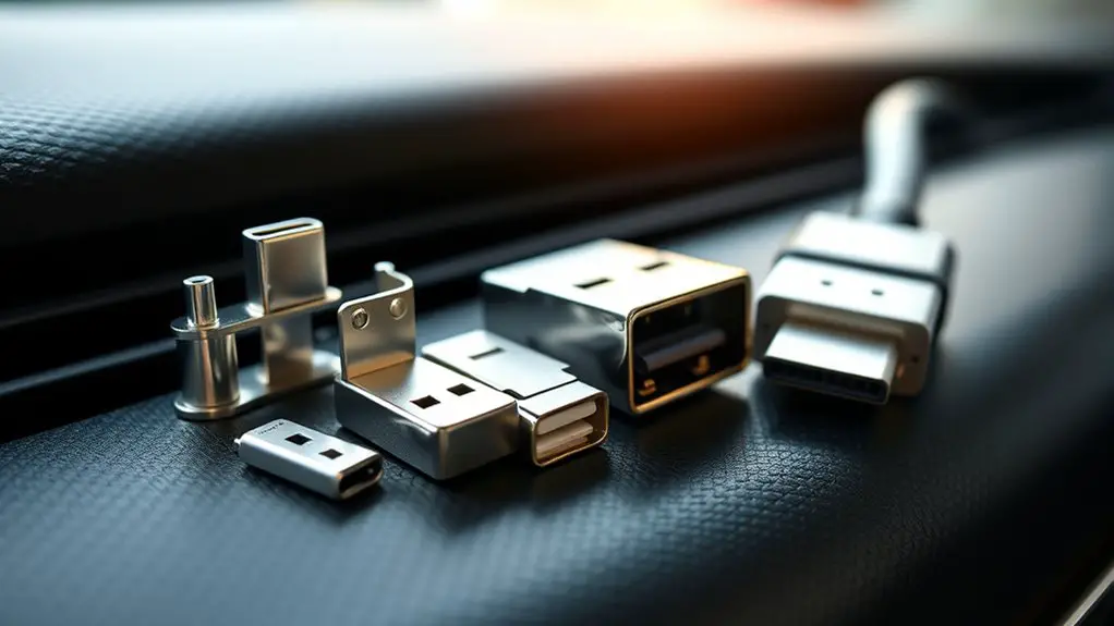
When selecting clips for USB-A and USB-C, you’ll compare clip styles and fitment against USB-A vs USB-C shapes to guarantee secure seating. Consider clip durability standards and materials, noting how each type withstands repeated insertions without deformation. Finally, verify connection compatibility tips to avoid misalignment and guarantee reliable engagement across port types.
USB-A Vs USB-C Clips
Choosing the right clips for USB-A and USB-C hinges on recognizing the physical and electrical differences between the interfaces; this guarantees secure, damage-free connections while preventing mix-ups.
- USB A features: you’ll align only one orientation, ensuring stable contact and predictable current paths without forcing fit.
- USB C advantages: reversible insertion, higher data rates, and broader power delivery support, enabling flexible panel testing setups.
- Selection approach: match connector receptacle shape to clip profile, verify shell dimensions, and confirm rated current before connection.
In practice, you’ll choose USB-A clips for legacy ports and USB-C clips for modern ports, coordinating wire routing and shielding to minimize noise. This disciplined pairing preserves port integrity and measurement reliability across testing scenarios.
Clip Durability Standards
Durability standards for USB-A and USB-C clips must account for repeated mating cycles, mating force, and enclosure integrity to guarantee consistent performance over time. You assess clip strength by simulating, with repeatable loads, the number of connect/disconnect events typical in your environment, then measure retention and disengagement thresholds. Material selection matters: clip materials should resist creep, wear, and aging while maintaining spring-back and contact alignment. For USB-C, account for asymmetrical mating and higher insertion forces in some sleeves, ensuring tolerances don’t degrade grip. Testing protocols should specify acceptable torque, deflection, and resonance behavior under vibration. Document failure modes clearly so you can iterate efficiently. Choose clips with proven endurance data that align with your panel, enclosure, and lifecycle expectations.
Connection Compatibility Tips
To select the right clips for USB-A and USB-C, focus on compatibility with your connector geometry, insertion force, and retention requirements. You’ll evaluate how each clip interfaces with distinct connection types, identifying potential compatibility issues early.
- Assess geometry fit: match clip jaws to USB-A and USB-C port outlines to minimize play and misalignment.
- Gauge insertion force: verify smooth engagement without excessive effort, reducing wear and debris risk.
- Verify retention and durability: confirm clip strength over repeated insertions and the ability to resist vibration or tension.
This methodical approach emphasizes precise selection, clear criteria, and freedom to adapt; it keeps you aligned with practical testing needs while avoiding unnecessary complexity.
Inspecting the USB Port and Panel for Compatibility
Inspecting the USB port and panel for compatibility begins with a clear, methodical check of physical fit and signaling support. You verify that the panel clip recess matches the USB port geometry, noting any misalignment that could cause stress or failure. Measure mounting depth, plate thickness, and edge clearance to confirm a flush, secure interface. Next, verify signaling compatibility by inspecting pin counts, shielding, and connector standard (USB-A, USB-C, or micro variants) as they relate to the panel’s integrated conductors. You assess contact integrity, verifying no corrosion, bent pins, or loose sleeves exist that would degrade performance. Panel material considerations come into play: dielectric strength, thermal behavior, and conductivity influence signal integrity and durability under repeated insertions. Document any deviations and plan corrective steps before test execution. Finally, verify the design accommodates strain relief and accessibility for practical use, maintaining freedom to service without compromising safety or reliability. USB port compatibility remains the guiding criterion.
Connecting Clips and Establishing a Safe Test Setup
Connecting the clips and establishing a safe test setup requires a clear harnessing of the prior compatibility checks. You’ll proceed with disciplined preparation, ensuring every connection aligns with the device’s pinout and labeling, and you’ll keep the workspace uncluttered for safe testing.
- Confirm clip connections match the USB port type and orientation, avoiding cross-contacts that could short.
- Ground yourself and the test surface, then verify insulation and strain relief to prevent movement during testing.
- Document each step and safeguard against accidental power application until all measurements are ready to begin.
Maintain a clean, deliberate sequence: attach, verify continuity, and recheck polarities before energizing. Use nonconductive tools where possible, and never bypass standard safety checks to chase results. This approach promotes reliable results while preserving your autonomy to test with confidence. By focusing on clip connections and safe testing, you reduce risk and improve repeatability, keeping the setup ready for accurate measurements without compromising personal or equipment safety.
Verifying Power Delivery With Panel Clips
Verifying power delivery with panel clips is a structured step—confirm the clip contacts align with the panel’s power rails, verify correct polarity, and measure the live voltage without loading the circuit. You’ll check that the positive clip lands on V+, the ground on return, and any sense or sense lines remain isolated unless needed for measurement. Use a multimeter in high-impedance mode to capture a stable reading, avoiding currents that could skew results. Record nominal USB voltage (usually 5 V) and compare against tolerance thresholds to gauge power efficiency and regulatory compliance. Inspect for consistent voltage as you introduce small load, noting any sag or transient spikes that indicate impedance or contact resistance. Maintain clean, tight connections, and document the exact panel clip position and voltage. This step sets the foundation for reliable testing, ensuring voltage stability while preserving safe, open access to the USB port.
Testing Data Integrity Across USB Lines
Begin by establishing a clean baseline: define the data lanes (D+, D−) and shield, verify proper terminations, and guarantee no power delivery changes during measurement.
You focus on USB data transfer and signal integrity as you measure across the lines with the panel clips. Keep the test environment stable, documenting reference levels and impedance Match. Avoid introducing noise sources during critical windows, and isolate any probing from the host controller.
1) Validate ADC or measurement points are centered within the common-mode range to prevent skew.
2) Record steady-state differential voltages and shifts, noting rise/fall times against expected USB spec.
3) Correlate timing jitter with observed bit errors, adjusting shielding or grounding if needed.
Result-oriented checks should confirm clean edges, minimal reflection, and consistent data parity. When you complete these steps, you’ll confirm data integrity across USB lines without compromising the system’s freedom to operate.
Interpreting Results and Common Fault Indicators
Interpreting results and common fault indicators builds on the prior measurements by translating raw signals into actionable diagnostics. You’ll compare channel amplitudes, timing, and impedance against defined USB panel-clip thresholds to form a clear verdict. Look for consistent deviations rather than single-point spikes, which often indicate measurement noise or transient events. Fault indicators appear as sustained boundary breaches, frequency-locked anomalies, or phase shifts that persist across multiple tests. Correlate voltage rail stability with data line eye patterns to confirm a port issue versus a cabling fault. Document whether results align with expected behavior for a given port type (USB-A, USB-C) and power role. When interpreting results, prioritize reproducibility: repeat tests under identical conditions, note environmental factors, and verify supply integrity. If several indicators point to a fault, classify it as likely hardware, not contact resistance alone. Use these conclusions to guide subsequent verification or replacement decisions with confidence.
Troubleshooting Tips for Faulty Ports or Connections
There are several practical steps you can take to diagnose and resolve faulty USB ports or connections without assuming the fault is the port itself. You’ll apply a disciplined approach that separates symptoms from root causes, focusing on repeatable checks and documented results. Use a tester, verify power and ground, and confirm data lines aren’t shorted or misrouted. If issues persist, re-seating and reseating again guarantees mechanical reliability before deeper analysis.
- Inspect for common connection issues and perform a controlled replacement of cables or devices to isolate the fault, noting impedance and continuity readings.
- Swap ports on the panel clip setup to determine if a single channel is degraded, and test a known-good device against multiple ports.
- Validate environmental factors (noise, EMI) and power supply consistency, recording any correlations with failures or intermittent behavior.
These USB troubleshooting techniques emphasize repeatability and objectivity, guiding you toward a factual conclusion without presuming port failure.
Best Practices for Re-testing and Maintenance
To maintain reliability in USB port testing, establish a repeatable re-testing workflow and document every step, result, and anomaly. You’ll define objective pass/fail criteria, record test conditions, and note any hardware changes. Keep a lean core process: baseline tests after panel clip installation, then targeted checks after connector swaps, firmware updates, or environmental shifts. Use a consistent test suite that covers power delivery, data integrity, and mechanical wear from clip insertion. Schedule periodic re testing frequency reviews to adjust based on failure history and device usage. Maintain a living log with timestamps, tool versions, calibration notes, and corrective actions. Integrate automatic alerts for outliers and drift, and align your maintenance schedule with production cycles or service windows. Prioritize traceability, reproducibility, and rapid rollback if anomalies appear. This disciplined approach sustains reliability while preserving your operational autonomy and sense of freedom.
Frequently Asked Questions
How Do Clips Affect USB-C Alternate Mode Testing?
Clips can affect USB-C alternate mode testing by altering mechanical stability and EMI paths, influencing measured performance. If clip stability is poor, connector movement can induce intermittent faults, skewing results. Guarantee clips maintain firm, repeatable contact without over-tightening. During tests, monitor USB C performance under defined flex and vibration profiles to verify consistency. Use reliable clips, minimize parasitic inductance, and document mounting conditions. Proper clip stability yields repeatable, accurate measurements in alt mode testing.
Can Panel Clips Interfere With Shield Grounding?
Yes, panel clips can interfere with shield grounding. You’ll want to verify shield integrity by tracing grounding paths from the USB shell to the device chassis, ensuring low impedance and solid contact. Check for loose or oxidized connections, and re-seat clips if needed. If shield integrity degrades, grounding issues may arise, causing EMI or signal noise. In your testing, document measurements and establish a repeatable method to confirm stable shield performance and reliable grounding.
Are There Safety Limits for Conducting Live Tests?
Yes, there are safety limits for conducting live tests. You should follow strict safety protocols, limit exposure, and only perform live testing within approved environments. Use insulated tools, eye protection, and verified equipment, and keep power off until connections are secured. Document procedures, risk assessments, and emergency stops. You’ll monitor voltages and currents with appropriate meters, ensuring isolation and clearance. Adhere to safety protocols, proceed deliberately, and maintain controlled conditions for responsible live testing.
How to Calibrate Voltage References for Clips?
You calibrate voltage references for clips by applying known standards and tracking the offset across the range. Use calibration techniques that pair a precision source with your meter, then adjust until your voltage measurement aligns within spec. Document each step, record ambient conditions, and verify in both rising and falling measurements. Maintain traceability, recalibrate after component changes, and perform periodic checks. You’ll gain confidence in accuracy, enabling reliable readings and consistent performance during debugging and testing.
What Are Signs of Subtle Data Line Crosstalk?
Subtle data line crosstalk presents as sporadic bit errors, marginal timing shifts, or occasional retries without obvious fault indicators. You’ll notice degraded data integrity when checksums fail more often than expected or payloads arrive with unexpected parity. Look for slight voltage or timing skew between adjacent lines, as signal degradation accumulates under load. Maintain clean routing, controlled impedance, and proper shielding to minimize crosstalk and preserve data integrity across high‑speed interfaces.