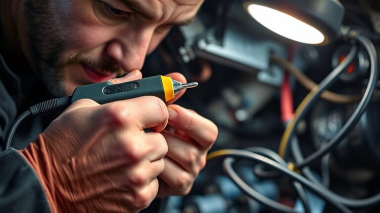
How to Use a Refrigerant Leak Detector to Find Refrigerant Leaks Causing Heater Blowing Cold
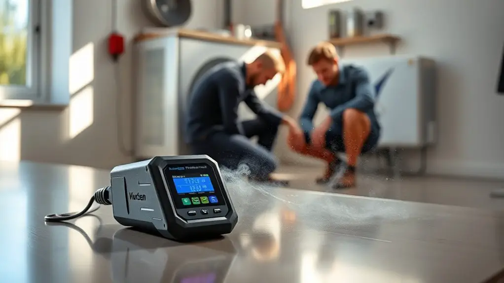
To find leaks that make your heater blow cold, start with a calibrated refrigerant leak detector. Position it near common leak paths at shoulder height and set a practical sensitivity for your system. Establish a zero baseline with clean air, then scan compressor connections, suction lines, and joints with a systematic sweep. Watch readings for peak signals and drift, confirming against baseline. If you detect a leak, stop the source, recover refrigerant, and test again after repairs for peace of mind. More tips await.
Understanding Refrigerant Leak Detectors
Understanding refrigerant leak detectors starts with knowing what they are and what they do. You’re using a tool that translates invisible gas into a measurable signal, so you can confirm leaks without guesswork. In practice, detectors come in handheld and fixed forms, with sensors tuned to specific refrigerants. You’ll select the right sensor, calibrate it, and run a baseline check before you sweep for leaks. Pay attention to response time, sensitivity, and alarms, which tell you when a threshold is crossed. Understanding refrigerant properties helps you interpret readings—different gases behave differently, disperse at varying rates, and linger near source points. Leak detection importance isn’t just about finding a drip; it’s about safeguarding efficiency, safety, and compliance. Follow manufacturer guidelines for testing procedures, surfaces to probe, and wind considerations. You’ll work fast, stay precise, and maintain your system’s performance by acting on accurate, timely detector feedback.
Why a Leak Causes a Heater to Blow Cold
A refrigerant leak can cause your heater to blow cold because the system loses enough refrigerant to knock the pressure balance off, preventing the heater from transferring heat effectively. When refrigerant escapes, the cycle can’t absorb and release heat properly, so you feel cold air even though the thermostat calls for heat. Reduced refrigerant means lower pressure, reduced heat capacity, and uneven heat distribution. This creates a perception of inefficiency and forces the compressor to run longer, chasing unstable temperatures. In short, leaks disrupt the designed thermodynamic balance, degrade comfort, and raise energy use.
| Effect | Result |
|---|---|
| Causes of leaks | Zones of weakness and undetected losses |
| Impact on efficiency | Lower heating output and higher runtime |
| Immediate symptoms | Cold air, longer cycles, higher bills |
Types of Refrigerant Leak Detectors
Different leak detectors vary in sensitivity, so you’ll choose one based on the refrigerant’s concentration you expect to encounter. You’ll also consider the detection technology—electronic sensors, soap tests, or ultrasonic methods—to match your application. Start by matching the detector’s sensitivity level and technology to the refrigerant type and typical leak size you’re targeting, then verify it meets relevant standards for reliable results.
Detector Sensitivity Levels
Detector sensitivity levels define how small a leak a detector can spot and how quickly it reacts. You’ll find devices rated for low, medium, and high sensitivity, each suited to different system pressures and refrigerants. Start with the lowest setting to establish a baseline, then incrementally raise sensitivity as you approach suspected zones. Expect faster response times at higher sensitivity, but be mindful of false alarms in busy environments. Use your instrument’s display or alarm behavior to gauge when a reading is meaningful, not noisy. Document the exact sensitivity level used during each scan for repeatability. Remember: sensitivity levels influence how you interpret readings. Mastering adjustment techniques helps you tailor detection to your system’s needs while preserving safety and efficiency.
Detection Technologies Used
There are several technologies used in refrigerant leak detectors, each with distinct strengths for different environments and refrigerants. You’ll encounter electrochemical, halogen, infrared, and soap-test variants, chosen by detector type and target gas. For practical use, match detection methods to your space: fast scanning, precise pinpointing, or long-range screening. When you move, observe steady readings, confirm with cross-checks, and perform leak analysis by narrowing the source to the smallest area possible. Maintain calibration, and document findings for repair teams. The goal is a quick, reliable read that guides safe, effective repairs. Table shows common options and their strengths.
| Detector Type | Best Use | Key Limitation |
|---|---|---|
| Electrochemical | Low-level GA leaks | Gas-specific drift |
| Halogen | Fluorinated refrigerants | Cross-sensitivity |
| Infrared | Large-area scans | Cost, depth limits |
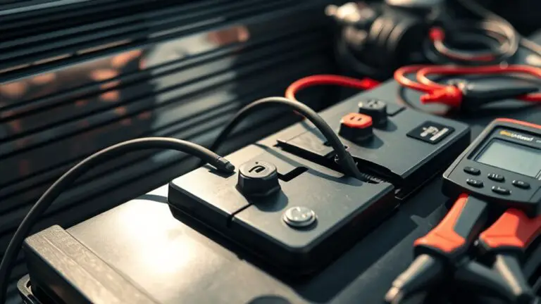
Safety Precautions Before Testing
Before you start testing, review all safety steps and wear appropriate PPE, including eye protection and gloves. You approach the task with clear, methodical focus. Inspect the area for visible hazards: loose wiring, exposed refrigerant lines, and ignition sources. Verify the detector’s calibration and function according to the manufacturer’s instructions, and confirm battery integrity. Ascertain proper ventilation to prevent gas accumulation; never test in confined spaces without ventilation. Keep a refrigerant leak context in mind: refrigerants can displace air and irritate eyes or skin. Wear safety gear beyond basic PPE if required by the system, such as a respirator or chemical splash shield. Establish emergency procedures: identify exits, have a fire extinguisher on hand, and know who to contact if symptoms occur. Maintain a clean workspace, remove clutter, and keep tools organized. If a leak is detected, stop work and reassess conditions before proceeding. Stay disciplined, and document any deviations.
Setting Up Your Detector for Your Heater System
Start by positioning the detector near common heater leak paths and at shoulder height for the best sensor exposure. Set the detector’s sensitivity to a practical level for your system, then run a quick baseline check and calibrate as recommended by the manual. Verify safety steps, lockout/tagout if needed, and note any unusual readings for follow-up checks.
Detector Placement Basics
To place a detector correctly, start by choosing high-traffic, central locations near the heater system where leaks are most likely to accumulate, such as on or near the heater enclosure, return air pathways, and areas above potential leak points. You’ll want detector positioning that gives you clear paths to rising gas pockets without clutter or obstructions. Place units at mid-height where convection carries refrigerant, then adjust for ceiling or floor constraints as needed. Make sure each detector isn’t blocked by insulation or ductwork and that lines of sight to potential leak points are open. Consider best angles that maximize sensitivity without creating dead zones. Test each position with a quick pass, then label and document findings for easy reference.
Sensitivity Settings Tips
Setting the right sensitivity on your refrigerant leak detector is essential for catching small leaks without triggering false alarms; start by selecting a baseline that matches your system’s typical leak rates and the detector’s specific sensor.
1) Establish baseline readings on a controlled test area, recording normal comfort-system fluctuations.
2) Adjust to a middle ground, then test with a known small leak to gauge responsiveness.
3) Fine-tune toward sensitivity adjustment strategies that highlight suspected zones without overreacting to ambient vapors.
4) Validate with repeat scans at different temperatures and speeds to confirm ideal sensitivity levels are consistent across operating conditions.
Note: document changes for future reference, and revert to a lower setting if nuisance alarms appear.
Safety and Calibration
Before you begin, apply the baseline you established for sensitivity and confirm the detector’s general readiness. You’ll follow safety guidelines and calibration procedures to set up the detector for your heater system. Check power, battery, and sensor leaks, then verify response to a known reference. Calibrate in a clean, ventilated space, away from strong drafts. Record baseline readings before you start testing components. During setup, secure mounting, verify cable integrity, and confirm alarm thresholds align with your system’s refrigerant type. Maintain a calm workflow, minimizing rapid movements. Table below helps you gauge progress and emotions as you proceed.
| Step | Focus |
|---|---|
| 1 | Safety mindset |
| 2 | Baseline verification |
| 3 | Calibration alignment |
| 4 | Readiness confirmation |
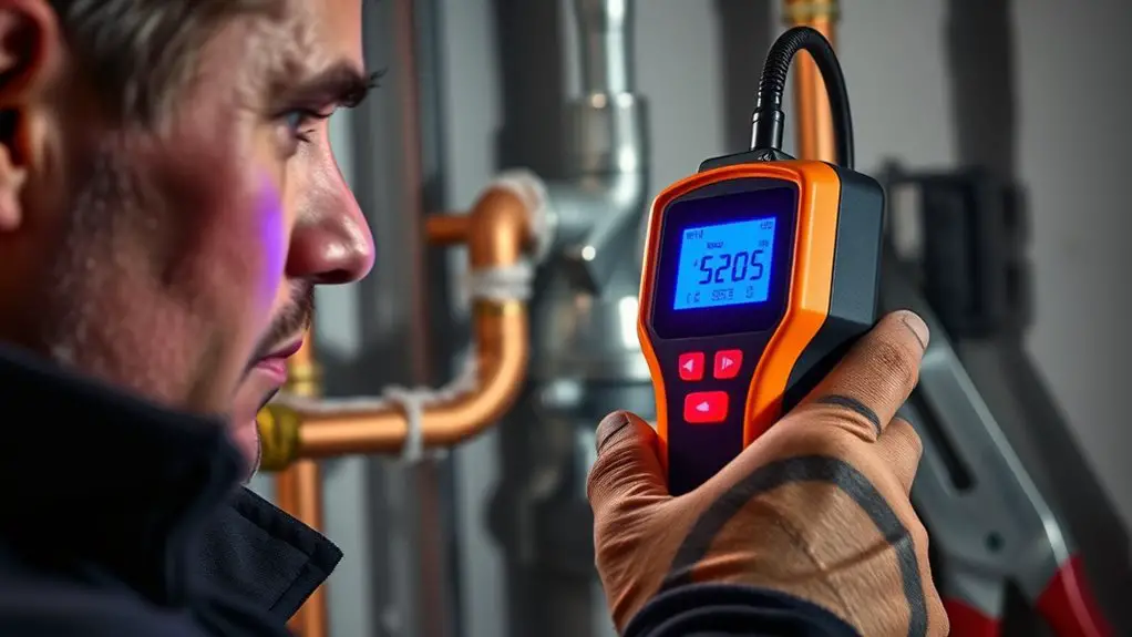
Calibrating the Detector for Accurate Readings
Calibrating the detector guarantees readings reflect the actual refrigerant levels, so start by powering the unit on and warming it to its operating temperature as specified in the manual. You’ll verify baseline behavior before you proceed with measurements.
Calibrate the detector by powering up, warming to spec, and verifying baseline readings before measuring refrigerant levels.
- Perform a quick self-test to confirm that the sensor stabilizes within the expected range.
- Establish a zero/reference point using clean, uncontaminated air so readings have a legit baseline.
- Apply a known calibration gas or a certified test source to confirm detector adjustments align with the target concentration.
- Record the response time and sensitivity, then fine-tune if the display lags or overreacts to minor changes.
Tips: keep the environment steady, avoid drafts, and handle calibration gas safely. Regularly revisit calibration techniques to guarantee consistent performance. If readings drift, retrace steps and recheck the reference point.
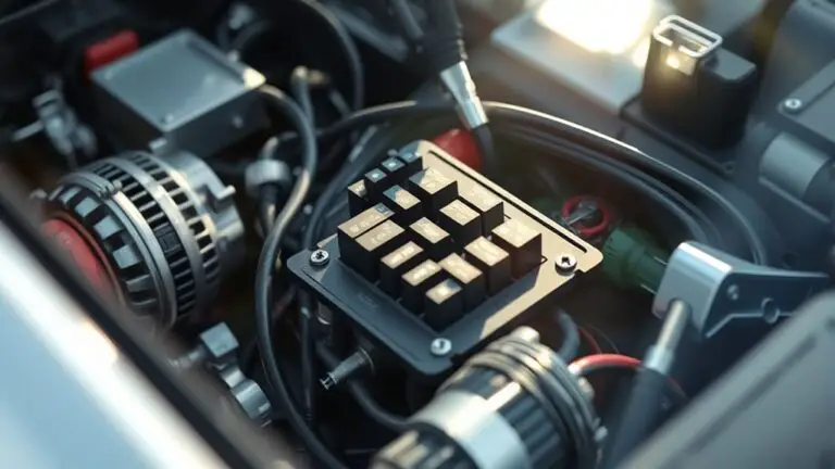
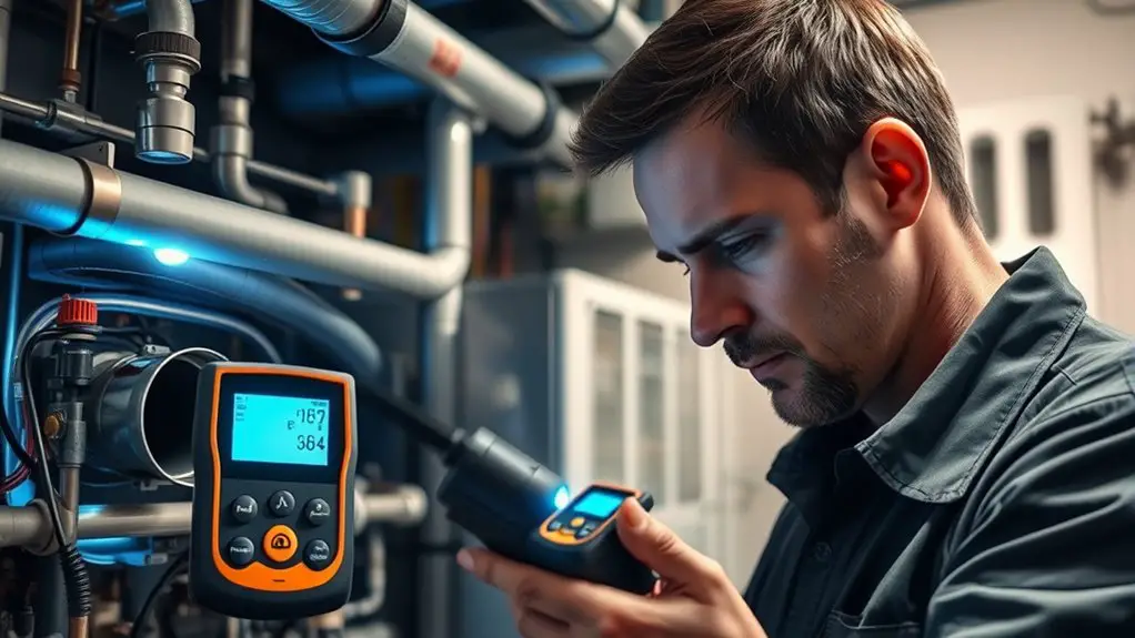
Scanning Typical Leak Points on the HVAC System
Start by outlining the Common Leak Points you’ll inspect, focusing on brazed joints, connections, valves, and compressors. Next, apply System Scan Techniques to methodically pass the detector along these areas, including fittings, condensate lines, and drain pans. Use Visual and Sensory Clues to guide you, noting any hissing sounds, oil residue, or color changes as you go.
Common Leak Points
Common leak points are where refrigerant escapes most often, so focus your scan on these areas first. You’ll want to map these typical leak locations to your detector readings and confirm with a visual check.
1) Compressor connections and service ports – tighten fittings if allowed, or note it for service.
2) Suction and discharge lines – inspect joints, insulated sections, and clamps for wear.
3) Condenser coil and access panels – look for damaged seals, loose mounts, or corrosion.
4) Refrigerant lines at the evaporator and expansion device – check for loose clips, leaks around fittings, and pipe stress.
Common leak sources and typical leak locations guide your initial sweep, keeping your search efficient and focused.
System Scan Techniques
To scan typical leak points efficiently, start with a systematic sweep of known hot spots: compressor connections and service ports, suction and discharge lines, condenser coil and access panels, and the evaporator/expansion device junctions. Move methodically, brushing or scanning each joint with the detector at a steady pace. Prioritize areas where vibration or thermal cycling occur, then verify with a secondary pass at slower speed. Note readings and temperatures that diverge from baseline; use leak detection confirmations before marking a leak point. Keep track of system efficiency indicators—unexpected pressure changes or cycling patterns can accompany leaks. Document findings for service planning, then retest after any repair to confirm leak detection and restoration of performance. Stay focused on accurate location to protect overall system efficiency.
Visual and Sensory Clues
Visual cues and sensory indicators can quickly point you to likely leak points. You’ll rely on concrete, observable signs rather than guesswork, focusing on both visual indicators and your sensory experiences.
1) Inspect joints and service ports for oily residues or crusty deposits around refrigerant lines—these telltale marks point to leaks.
2) Listen for faint hissing near connections; a sustained tone can mark a leak path.
3) Look for frost or ice on copper tubing, evaporator coils, or compressor fittings; cold spots reveal refrigerant loss.
4) Note unusual odors or chemical scents near components, and confirm with your detector to verify the suspected area.
Use these clues methodically, confirming with measurements and the leak detector as you proceed.
Interpreting Detector Readings and Indicators
Interpreting detector readings and indicators requires a methodical approach. You’ll verify current readings, note baseline values, and compare against the detector’s stated sensitivity. Start with detector calibration—confirm the unit is calibrated for the refrigerant type you’re tracing and that the response time aligns with the manufacturer’s guidance. Then perform a controlled baseline read away from any suspected leaks to establish a reference point you can trust. As you move, track real-time signals: peak readings, drift, and any intermittent spikes, documenting time, location, and ambient conditions. Distinguish true refrigerant signals from background odors, solvents, or hot surfaces by cross-checking with a second sensor or a known leak source. Look for consistent, directional increases toward fixtures, coils, or joints. If readings approach the manufacturer’s leak detection threshold, verify with repeated passes. Don’t assume—confirm via repeated measurements and proper detector calibration to guarantee accurate leak detection.
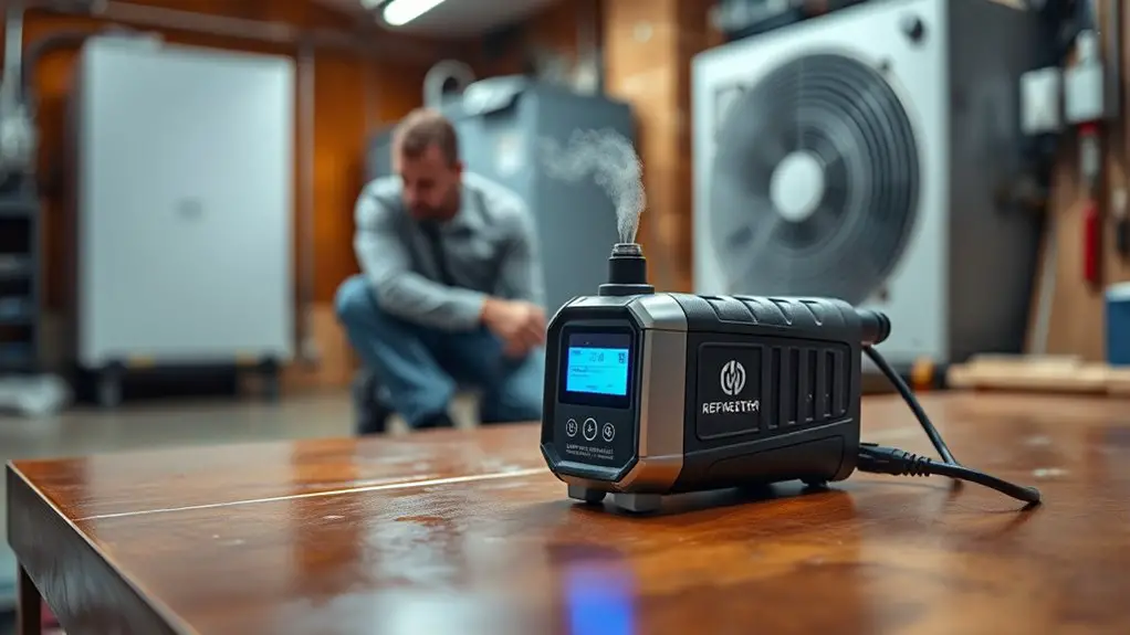
What to Do After a Detected Leak
Once a leak is detected, you should stop the source, isolate the affected area, and begin containment steps. Then proceed with a practical plan to address the fault without delaying critical action.
When a leak is detected, stop the source, isolate the area, and begin containment before addressing the fault.
1) Identify the leak’s location and assess safety hazards before you touch any components.
2) Perform leak repair only if you’re qualified; otherwise call a licensed technician to guarantee proper sealing and system integrity.
3) Initiate refrigerant recovery per applicable regulations to prevent environmental release and prepare for recharging.
4) After repairs, verify that the system holds its charge, perform a thorough leak test, and document results for compliance.
Keep notes on the repair method, recovery equipment used, and the test readings. If you cannot complete leak repair immediately, isolate the equipment and arrange professional service promptly. Focus on safe, compliant steps to restore function while preserving system efficiency and safety.
Maintenance and Best Practices for Future Prevention
To prevent future leaks, establish a routine that includes regular inspections, proper charging practices, and ongoing system monitoring. You’ll map inspection points, focusing on hoses, fittings, and valves for signs of wear or corrosion. Schedule refrigerant maintenance at manufacturer-recommended intervals and after any service that involves the system’s sealed parts. Calibrate detectors and verify airtight connections before charging. Document pressures, temperatures, and refrigerant type during every service to track anomalies over time. Use correct charge amounts, avoiding overfill and undercharge, and follow recovery rules to minimize vented refrigerants. Implement a leak-prevention checklist for technicians, including a tightness test after repairs and repeated checks in the first 48 hours. Train staff to recognize early indicators like minor hissing, oily residue, or frost nearby. Maintain an inventory control system to prevent cross-contamination of refrigerants. This disciplined approach supports refrigerant maintenance and leak prevention, promoting reliable heating performance and environmental responsibility.
Frequently Asked Questions
Can I Use a Leak Detector on a Live Electrical Panel Safely?
Yes, you should avoid using a leak detector on a live electrical panel. You risk shock, arc flash, or equipment damage. Turn off power, verify de-energized status, and follow lockout/tagout procedures before testing. If you must inspect, consult electrical safety guidelines and use appropriate PPE, non-contact methods, or get a licensed electrician. Safety first for live panel safety, electrical safety, and your risk management. Never bypass standard procedures for freedom from frustration.
How Often Should I Replace the Sensor Within the Detector?
You should replace the sensor according to the manufacturer’s recommended interval, typically every 2–5 years, but check your model’s specifics. Regular detector maintenance keeps readings reliable, so log calibration and response tests. If readings drift or you notice delayed alerts, replace the sensor sooner. Maintain a routine; don’t ignore warning LEDs or false positives. Keeping sensor lifespan in mind helps you stay safe and confident while diagnosing leaks and protecting equipment uptime.
Do Refrigerant Detectors Detect All Refrigerants With Equal Sensitivity?
Most detectors don’t detect all refrigerants with equal sensitivity. You’ll find varied response across refrigerant types, so you must know your detector’s spec sheet. For best results, check both refrigerant types and detection methods in your device’s manuals, and test with known gases when possible. About 20–30% of leaks go undetected by some models, so verify with complementary methods. Stay practical, precise, and flexible as you work across refrigerant types and detection methods.
Can Room Temperature Affect Detector Accuracy During Testing?
Yes, room temperature can affect detector accuracy during testing. You should allow the detector to settle at ambient temperature, then verify ambient temperature readings match the device’s calibration. Before testing, perform detector calibration at the room’s temperature to avoid drift. Maintain consistent ambient temperature during measurements, and recount results if the temperature shifts. This practical approach helps guarantee reliable leak detection, especially when chasing refrigerant leaks that cause a heater to blow cold.
Is It Safe to Test Leaks Near Chimney or Furnace Exhaust Ducts?
Yes, you can test leaks near chimney or furnace exhaust ducts, but prioritize safety and proper procedures. Keep ignition sources away, wear PPE, and avoid blocking vents. Follow chimney safety and exhaust duct considerations, monitoring for fumes and heat. Use a detector with appropriate sensitivity, maintain distance from exhaust streams, and guarantee area is well-ventilated. If in doubt, shut down the system and consult a professional. Proceed cautiously, then verify findings with repeat testing.