Step-By-Step: Repairing a Wheel Hub Noise Caused by a Damaged Tire Inflator
To fix a wheel hub noise caused by a damaged tire inflator, start by safely immobilizing the vehicle and isolating the inflator. Inspect mounting points, fasteners, seals, and the inflator port for wear, cracks, or looseness. Replace worn parts with OEM-compatible components and re-secure all connections with calibrated torque. After reassembly, perform a controlled test drive, listening for changes in noise and monitoring steering, vibration, and brake behavior. If issues persist, you’ll uncover more detailed steps ahead.
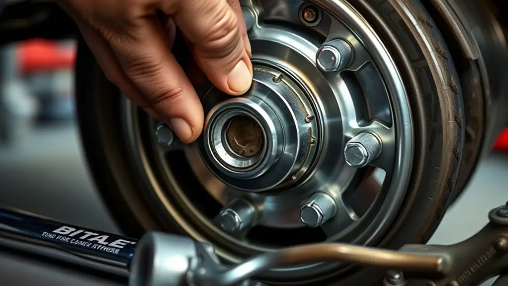
Diagnosing a Wheel Hub Noise Linked to the Tire Inflator
A wheel hub noise linked to the tire inflator can originate from the inflator’s vibrations transferring through the wheel and brake components. You’ll assess whether the sound aligns with engine rpm, wheel rotation, or tire inflation events. Start by isolating the inflator: disconnect or power it down to determine if the noise persists without air pressure input. If the noise ceases, it points to the tire inflator’s mechanical resonance interfacing with the wheel hub assembly. Inspect mounting hardware for looseness and check hose connections for chafing or misalignment that could amplify vibration. Use a stethoscope or screwdriver leverage to localize sound direction, noting whether it emanates from the hub bearing area or the brake rotor surface. Document conditions, including temperature, wheel position, and inflation level. If resonance remains after isolating the inflator, consider swapping components in the path to the wheel hub to eliminate the source. Maintain safety and precision throughout the diagnostic process.
Tools and Safety Precautions for the Inspection
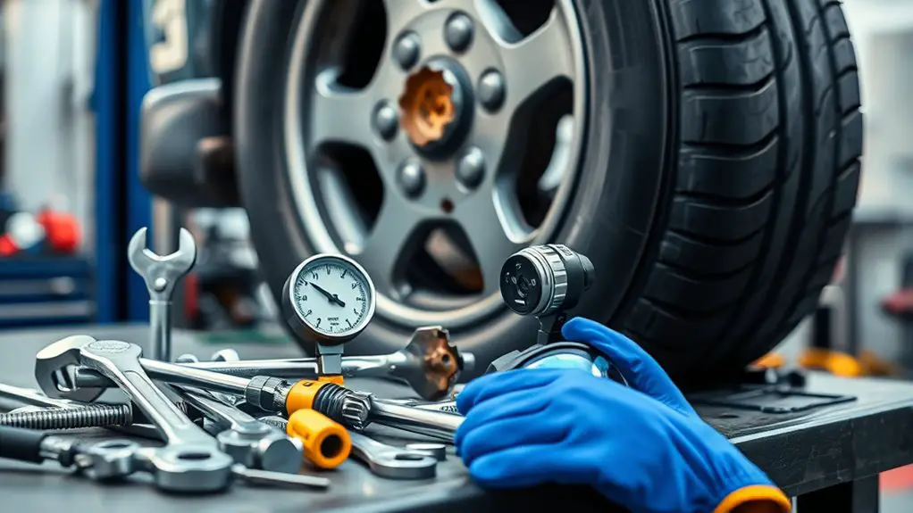
You’ll start by evaluating PPE and gear, ensuring you have gloves, eye protection, and hearing protection ready before inspections. Follow strict inspection protocols and document findings methodically to keep track of wear, torque specs, and observed anomalies. Adhere to tool handling rules—keep blades, bits, and fasteners organized, secure clamps, and maintain a clean workspace to prevent mishaps.
PPE and Gear
Before inspecting a wheel hub, gather appropriate PPE and gear to protect yourself and guarantee a safe workflow. You’ll rely on precise safety equipment and personal protection to minimize risk during inspection and handling. Stay lean, focused, and prepared.
- Safety glasses or face shield to guard eyes from debris
- Mechanic gloves for grip and cut protection
- Steel-toe boots for foot safety and stability
- Hearing protection in noisy environments
- Durable workwear with reinforced seams for abrasion resistance
Choose compact tools and a tidy workspace to reduce trips and distractions. Maintain awareness of pinch points and hot components, and verify PPE integrity before use. Your freedom to work confidently hinges on disciplined safety habits, not shortcuts. Prioritize comfort, fit, and visibility, ensuring every move is deliberate and protected.
Inspection Protocols
Because accurate inspection hinges on safe practice, start by confirming the vehicle is immobilized and the hub area is accessible without pinching hazards. You’ll verify lighting, cleanliness, and stability before touching components. Use a calibrated measurement reference for axial play and runout, and document any deviations. Prioritize tire maintenance relations: check tire pressures, wheel alignment marks, and valve integrity without forcing components. Inspect the inflator port and surrounding hub surface for cracking, corrosion, or residue that could indicate leaks. When you probe, keep tools aligned, avoid twisting the hub, and remove obstructions only after de-energizing the system. Personal safety stays primary; wear gloves, eye protection, and secure loose parts. This protocol supports noise reduction by confirming proper seating and preventing transient disturbances during inspection.
Tool Handling Rules
Handling tools safely is essential during inspection: always select the right tool for the job, inspect for damage before use, and keep blades, tips, and jaws clean and dry.
You’ll approach tool handling with precision: select purpose-built instruments, test calibration when applicable, and avoid improvised fixes. Stay mindful of tool safety, wear appropriate PPE, and maintain a steady workspace to prevent slips. Equipment organization is not optional—return items to designated spots after use and label containers for quick access. Document tool condition and spares to minimize downtime during inspection. Keep cords untangled, batteries charged, and torque settings verified. Communicate risks clearly with teammates, and suspend work if instability arises.
- Right tool first
- Inspect for wear
- Clean and dry
- Organized workspace
- Document and tag
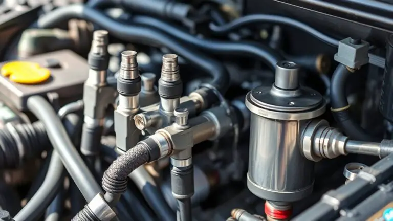
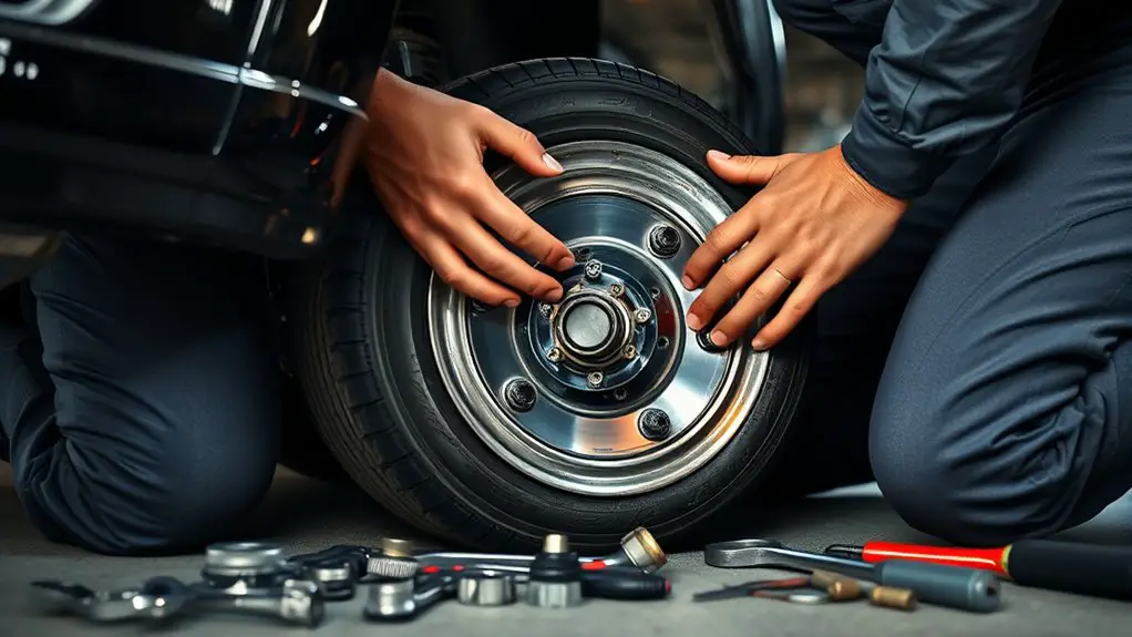
Accessing the Tire Inflator and Related Components
Accessing the tire inflator and its related components is a straightforward, methodical step in diagnosing wheel hub noise. You’ll locate the inflator housing, quick-connect fittings, and mounting points with clear purpose, then assess access paths for safe inspection. Verify the vehicle is secure, wheels chocked, and power disconnected before touching any electrical or pressurized elements. Inspect the inflator for secure connections, signs of wear, and corrosion at all harnesses and terminals. When you test tire inflator functionality, use controlled, deliberate motions to avoid disturbing surrounding components. Document any looseness or movement that could translate into noise, noting exact locations for future reference. Apply noise reduction techniques only where you can verify influence on the noise source, avoiding unrelated parts. Keep hands clear of moving belts and pulleys, and maintain a clean workspace to prevent contamination. This step supports precise diagnostic conclusions and safer, freer hands-on work.
Identifying Signs of Damage on the Inflator
You should inspect for visible wear indicators on the inflator and note any cracks or chipped housings. Look for leakage signs such as hissing, dampness, or fluid residue, and verify if seals or connectors show deformation. Record functional testing results, confirming actuator responsiveness, pressure hold, and leak checks to guide further diagnosis.
Visible Wear Indicators
Visible wear indicators on inflators reveal damage signs that affect performance and safety. You’ll notice subtle changes in texture, finish, and alignment that betray ongoing wear without a full failure yet. Scratches, scoring, or rounded corners on nipple seals, gauge housings, or connectors signal degradation. Cracked housings, chipped rims, or swollen grips reduce precision and reliability during tire maintenance. Inconsistent air flow, sluggish gauge response, or leaked seals accompany visible wear, hinting at reduced noise reduction capabilities. Hydraulic or rubber components show hardening or soft spots, compromising seal integrity. Track these signs to prevent cascading issues and maintain safe, efficient operation. Address wear early to sustain performance and minimize unnecessary downtime.
- Faded or discolored seals and gaskets
- Hairline cracks on housings or nipples
- Worn or deformed gauge needles
- Loose, detached, or misaligned fittings
- Brittle, swollen, or creased hoses
Leakage Signs Observed
Leakage signs are the first and most reliable indicators of inflator damage. You’ll notice dampness around seals, hose connections, or the nozzle, signaling a breach that compromises performance. Look for continuous or sporadic seepage during operation, especially when the unit is pressurized. A crack or split in the housing may manifest as visible moisture emanating from joints, while gaskets can show swollen edges or misalignment. Inconsistent air flow suggests internal leakage, and audible hissing points to pressure loss pathways. Perform leak detection with the unit powered and connected to a test source, noting any pressure decay that exceeds baseline expectations. Track air pressure readings during normal use; abnormal drop rates confirm the need for inspection or repair before further use.
Functional Testing Results
Functional testing reveals concrete indicators of inflator damage, including abnormal pressure trends, erratic cycling, and unexpected noise patterns. You’ll assess the inflator under load, compare readings against baseline, and document anomalies during the noise assessment. Precision here matters: detect subtle swings, jerks in cycling, and irregular venting sounds that diverge from normal operation. If readings skew or drift, you likely face seal wear, diaphragm failure, or valve sticking. Record timing, amplitude, and frequency of fluctuations to map failure mode. Use this data to guide a targeted repair plan rather than replace parts blindly. Your goal is a trustworthy seal and stable pressure delivery, with minimal noise intrusion during inflation and driving.
- Abnormal pressure drift during cycling
- Irregular venting sounds
- Inconsistent cycle timing
- Sudden abrupt pressure changes
- Persistent minor noise during steady state
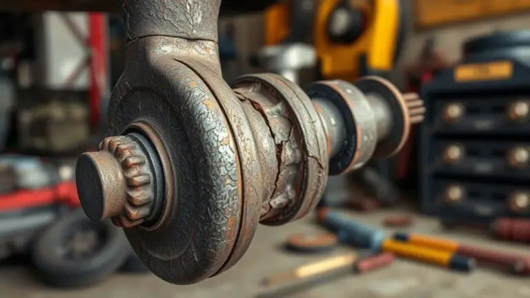
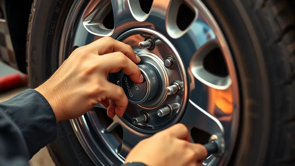
Inspecting Mounting Points and Fasteners
Inspecting mounting points and fasteners begins with a systematic check of all hub-to-rack or knuckle connections. You methodically verify that each fastener is present, properly seated, and aligned with its mounting surface. Look for signs of corrosion, thread damage, or unusual wear on bolts, studs, and nuts. Check washers and spacers for correct orientation and compatibility with the hub design. You confirm that mounting points show no cracks, deformation, or distortion that would alter alignment or load paths. Use a calibrated torque method or manufacturer specs to assess tightness, noting any looseness or over-tension that could affect performance. Document observations, replacing any fastener showing signs of fatigue or stripped threads to preserve mounting stability and fastener integrity. Re-check after any adjusted or replaced hardware to verify consistent clamping force. Ascertain clearances remain within spec, and that the hub remains securely anchored to the knuckle or rack for reliable operation.
Testing for Noise Causes Beyond the Inflator
Have you considered noise sources beyond the inflator when diagnosing hub hums or grinding? This section guides targeted testing to distinguish inflator issues from other contributors. Conduct controlled observations, noting pitch, timing, and load dependency. Emphasize noise diagnostics to isolate sources, and keep inflator maintenance records for correlation. Limit variables during tests to avoid false positives.
- hub bearing play signaled by consistent low-frequency howl
- wheel offset or suspension rub creating irregular chatter
- brake rotor edge contact producing metal-on-metal squeal
- tire tread cupping or belt separation manifesting rhythmic thumps
- steering linkage or CV joint interaction changing with lock-to-lock turns
Proceed with a systematic checklist: verify mounting integrity, cycle key components, and compare with a known-good tire setup. Document accelerations, decelerations, and road surface changes. If the noise persists beyond inflator tests, extend diagnostics to adjacent housings and seals. Maintain clear notes to inform future inflator maintenance decisions and prevent misattribution.
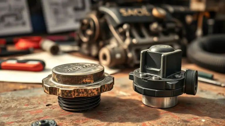
Replacing Worn or Damaged Inflator Parts
Inspect the inflator for wear indicators and replace any damaged components to prevent leakage and inaccurate readings. After swapping worn parts, reassemble the assembly, ensuring seals, threads, and fasteners engage properly. Finally, test the system for proper inflation behavior and absence of noise before returning to service.
Inspect Inflator Wear
Inflating hardware can wear over time, and a worn or damaged inflator part can compromise accuracy and safety. You perform a precise wear assessment to determine if the inflator still meets performance specs, noting any loss of responsiveness, leaks, or inconsistent pressure readings. Inspect seals, connectors, and the barb fitting for cracks or looseness, and check the gauge alignment against a reference. If any component shows degradation, plan the appropriate maintenance action before further use. Maintain a log for inflator maintenance, including dates and observed symptoms, to track wear trends and forecast replacement timing. This focused evaluation keeps your system reliable and safe, reducing surprises during field inflation and preserving wheel-hub integrity.
- Worn seals show cracking or stiffness
- Leaks around joints become audible
- Gauge misalignment versus reference
- Connector looseness at fittings
- Visible wear on o-rings or seals
Replace Damaged Components
When you replace damaged components, remove and label worn parts before installing replacements, ensuring compatibility with the inflator model and wheel-hub interface. You’ll verify each candidate part against the manufacturer’s specifications, avoiding generic substitutes that could alter tolerances. Inspect seals, gaskets, and connectors for signs of degradation; replace any with visible cracks or stiffness. Confirm fastener sizes and thread pitches match the original hardware to prevent cross-threading. Prioritize component compatibility, selecting parts designed for your inflator’s operating range and duty cycle. Document part sourcing details, including supplier, part numbers, and batch codes, to support future maintenance. After installation, perform a functional check of alignment, seating, and leak indicators. Maintain a concise record to streamline future diagnostics and keep performance predictable.
Reassemble and Test
Having identified and replaced worn or damaged inflator components, proceed to reassemble the assembly and verify proper function. You’ll apply precise reassembly techniques to restore alignment, seals, and fasteners, ensuring no leaks or misfits. Align every interface with care, tighten to spec, and confirm that the trigger and gauge respond cleanly. Next, perform careful testing procedures: inflate with a controlled supply, observe gauge accuracy, listen for abnormal sounds, and check for spontaneous deflation. If readings deviate, recheck seals and valve seating before re-testing. Once stable, cycle the inflator to full operation to validate reliability under load.
- Proper alignment of interfaces during reassembly
- Seals seated without distortion
- Trigger and gauge responsiveness verified
- Leak checks at all joints and fittings
- Repeated tests to confirm sustained performance
Reassembling and Securing the System
To reassemble and secure the system, start by aligning all components precisely as they were removed, then torque fasteners to the manufacturer’s specifications. You’ll re-establish the correct fitment, verify that seals sit properly, and guarantee that the hub assembly spins freely without binding. Follow a deliberate sequence: reinstall the rotor or flange, then reattach brackets and sensors, keeping fasteners in marked positions. Use clean, thread-cleaning practices to avoid cross-threading, and apply the specified lubrication only where indicated. During reassembly techniques, confirm that the drum or wheel carrier mates squarely with the hub after each step. Tighten in a crisscross pattern where applicable, and avoid over-torquing which can warp components or distort seals. After all fasteners are set, perform a tactile check for smooth rotation, listening for intermittent drag. Finally, recheck alignment marks and sensor clearances, guaranteeing the system remains balanced and ready for function. This secures components and preserves long-term reliability.
Verifying the Repair With a Test Drive
With the reassembled hub now secured, take the vehicle for a controlled test drive to confirm the repair’s effectiveness. You’ll listen for any lingering or new sounds while your focus remains on stability, steering behavior, and braking response. Begin at a low speed, then progressively increase to highway pace to reveal tire-inflator related disturbances that may reappear under load. Compare road surfaces and weather effects, noting whether the noise persists, changes in pitch, or shifts with vehicle speed. Use precise, methodical checks rather than guesswork to validate that the repair holds under real driving conditions. If no abnormal sounds appear and handling remains consistent, you’ve achieved noise verification and earned confidence in the fix. If something returns, halt, re-assess, and repeat the inspection steps before extending the test.
- Calm, deliberate accel and decel through varied speeds
- Smooth lane changes to test stability
- Consistent steering feedback without play
- No vibrations at different rpm levels
- Clear, repeatable silence once confirmed
Preventive Maintenance and Future Checks
Preventive maintenance and future checks focus on safeguarding the hub assembly and preventing recurrence. You’ll establish a quick, repeatable routine that reinforces reliability without slowing your progress. Start with tire maintenance basics: inspect pressures, tread wear, and valve stems regularly; verify seals aren’t compromised by over- or under-inflation; replace damaged inflators promptly. Keep wheels clean to avoid contaminant buildup that can mask early wear signals. Track hub fasteners for proper torque, recheck after driving cycles or service events. Listen for shifting tones or new noises during gentle acceleration or deceleration, and address them before they escalate. Document service dates, observed conditions, and corrective actions for future reference. Use a quality torque wrench, calibrated tools, and OEM specifications to sustain consistency. Incorporate noise prevention into your routine by monitoring alignment, bearing play, and rotor surface condition. This disciplined approach reduces downtime and preserves performance, letting you maintain freedom with confidence.
Frequently Asked Questions
How to Differentiate Hub Noise From Tire-Related Noises?
Yes, you differentiate by isolating symptoms: tire noises rise with speed or steering input and change with road surface, while hub noises stay steady and often worsen with vehicle load or brake application. Check tire wear patterns and rotation for irregularities, then inspect hub bearings and alignment. Listen for grinding near the wheel as you accelerate, and verify alignment after tire rotation. If uncertain, perform professional inspection to confirm hub alignment and tire wear causes.
Can Inflator Type Affect Hub Noise Severity?
You bet: inflator types can influence noise levels, but not the hub’s core defect. You’ll notice louder, sharper sounds when a high-pump, rapid-cycle inflator stresses the tire and wheel assembly. As pressure fluctuates, vibrations travel, coloring the hub noise. You’ll compare inflator types and gauge noise levels, then isolate the source. You should test under controlled conditions, document readings, and consider wear on bearings or rotors if the noise persists beyond inflator-related changes.
What Signs Indicate Immediate Safety Risk During Testing?
Signs of immediate safety risk during testing include uncontrolled wheel movement, brake drag, or sudden loss of braking efficiency. If you notice a grinding or hissing from the hub, overheating, or abnormal tire pressure fluctuations, stop and inspect. Confirm brake inspection and tire pressure checks are performed before any test run. Maintain secure mounting, use proper restraints, and avoid high speeds until components are verified within spec. If unsure, halt and consult a professional.
Do Aftermarket Inflators Void Vehicle Warranties?
Yes, aftermarket inflators can affect warranty considerations. You should check your vehicle’s warranty terms and the inflator’s compatibility, as some manufacturers issue exclusions or require approved brands. Using aftermarket products may void claims tied to related components if damage is linked to them. Stay mindful of installation correctness and documentation. If in doubt, consult the dealer. You’ll protect yourself by understanding coverage limits and keeping receipts, specs, and calibration records for evidence.
How Often Should Inflator Seals Be Inspected?
You should perform seal maintenance checks every six months or 6,000 to 8,000 miles, whichever comes first. Regular inspection frequency helps you catch wear early and prevent leaks. When you inspect, look for cracking, hardening, or bulging along the seal edges. If you find damage, replace promptly to maintain pressure stability. Keep notes on inspection frequency and any findings to sustain peak performance and seal integrity for your system.