Step-By-Step: Replacing a Failing Oxygen Sensor That Causes Check Engine Light for Emissions
To replace a failing O2 sensor causing the check engine light and emissions issues, start by diagnosing with your scan tool to confirm sensor fault and rule out leaks. Gather a replacement sensor, gasket, anti-seize, short-wrench, and an oxygen sensor socket. Locate the sensor along the exhaust path, remove carefully, and clean threads before install. Torque to spec, reconnect wiring, and clear codes. Then reset the ECU and test drive to verify proper sensor swings and readiness monitors—you’ll uncover more details if you keep exploring.
Diagnosing the Problem: Is the Oxygen Sensor the Culprit?
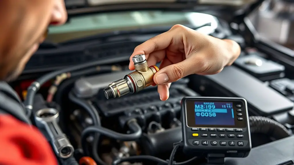
Before replacing anything, verify whether the oxygen sensor is actually the source of the issue. You’ll begin with symptom identification, noting check engine light patterns and any rough idle, misfires, or gas mileage changes. Gather data from the vehicle’s onboard diagnostics and correlate it with your observed symptoms. Assess sensor functionality by checking for plausibility: reference values, response time, and switching behavior during steady-state and transients. Use a scan tool to monitor real-time O2 sensor readings, comparing upstream and downstream sensors to expected air-fuel ratios. Look for heater circuit faults, circuit continuity, and grounding integrity, as failures here mimic sensor problems. Rule out common culprits like vacuum leaks, dirty MAF, or exhaust leaks that skew readings. Remember not all CELs point to the sensor alone; sometimes upstream catalysts or fuel delivery influence results. Once the data align with sensor symptoms, you’ll have a focused path for confirmation testing and a reliable diagnosis of sensor functionality.
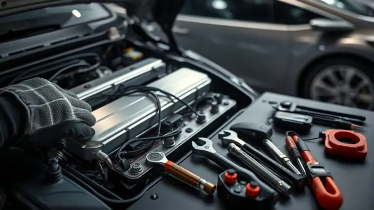
Tools and Parts You’ll Need for the Swap
You’ll need a reliable socket set, a torque wrench, and an O2 sensor socket to remove and install the replacement securely. Have the correct replacement sensor on hand, plus wiring anti-seize or anti-corrosion grease if specified by the manufacturer. Gather any specialty parts your vehicle requires, such as an O2 sensor gasket or thread sealant, to guarantee a leak-free fit.
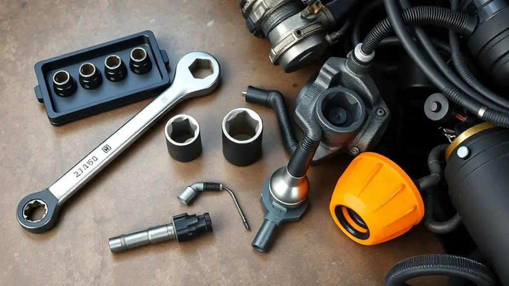
Essential Tools List
A solid tool and part list keeps the job moving smoothly: you’ll need a mix of standard hand tools, diagnostic gear, and the right oxygen sensor replacement parts. Begin with essential tools: a ratchet, sockets (including a shallow and deep 7/8” or as your sensor requires), wrenches, pliers, and a torque wrench to spec. Add a multimeter or OBD-II scanner for sensor readings, plus thread sealant if OEM specifies it. For sensor specs, verify the replacement matches your vehicle’s exact sensor type, heater circuit, and connector. Keep penetrating oil, gasket/elbow greases, and anti-seize handy. Have safety gear—gloves and eye protection. Document the sensor specifications and mounting torque so you hit accurate reinstallation. This keeps the swap efficient and reproducible.
Required Replacement Parts
To swap in a new oxygen sensor, you’ll need a precise mix of replacement parts and tools tailored to your vehicle. Start with the sensor itself, selecting the correct type (OE or equivalent) for your exhaust manifold and bank configuration. Gather a fresh gasket or O-ring if your model uses one, plus anti-seize compound for the threads and a dielectric grease for electrical connectors. Include a replacement harness or connector if the old one is damaged. Have a torque wrench set to the manufacturer’s spec and the appropriate sockets. Don’t skip a replacement tubing or adapter if your system requires it. Replacement parts overview, sensor compatibility check, and verified parts lists reduce rework and protect emissions integrity.
Locating the Oxygen Sensor on Your Vehicle
Locating the oxygen sensor on your vehicle is the first step before any replacement. You’ll identify sensor locations and sensor types by tracing exhaust flow from the engine to the tailpipe. Look for sensors mounted in the exhaust manifold, downpipe, and near the catalytic converter. Use your vehicle’s service manual or a reputable repair guide to confirm exact positions for your model.
| Sensor location | Typical wiring harness | Common symptoms |
|---|---|---|
| Near exhaust manifold | High-temp connector | Rich/lean readings |
| Downstream after catalytic converter | Anti-turge wiring | Emissions fault codes |
| Post-cat in exhaust pipe | Long loom | Engine light behavior |
| Behind or near the muffler | Shielded connector | Performance irregularities |
Note: this step focuses on locating oxygen sensor locations and sensor types to plan replacement accurately. Avoid disassembly beyond diagnosis; precision saves time, heat exposure, and risk.
Preparing Your Vehicle: Safety and Best Practices
Before you begin work, make certain you’ve gathered the right safety gear and tools, and confirm the vehicle is stable and supported. You’ll approach this with a calm, methodical mindset, because steady preparation reduces risk and protects your freedom to fix on your terms. Start with common safety gear: gloves, eye protection, and a sturdy jack stand beneath the chassis. Verify the parking brake is engaged and the engine is cool before touching hot components. Keep a clean workspace, use proper lighting, and organize fasteners so nothing gets misplaced. Adhere to basic vehicle maintenance practices: disconnect the battery if you’ll be near electrical sensors, avoid forced detours around sensors, and never work under a load-bearing lift without double-checking support. Document steps as you go to support future maintenance. This mindset—safety-first, precise, and self-reliant—empowers you to replace the oxygen sensor efficiently and safely.
Removing the Faulty Sensor Without Straining Wires
To remove the faulty sensor without straining wires, start by locating the wiring harness and any protective loom around the sensor for safe access. Use proper disconnect steps, keeping tension off the wires and avoiding sharp bends as you detach connectors. Maintain clear access and plan your route for reinstallation, focusing on Wiring Access Tips and Safe Disconnect Steps.
Wiring Access Tips
Accessing the sensor wires without stressing them starts with a careful, methodical approach. You’ll map out wiring diagrams first, so you know where every connector and loom runs. Identify access points that give you room to work without tugging on harnesses, then plan your path to the sensor with minimal bending. Use proper lighting and a magnifier if needed, so you don’t miss fragile pins or clips. When you disconnect, support the harness from its mount and keep your hands steady to avoid wiggling the connector. Label connectors and reference points as you go, preserving orientation for reinstallation. Keep tools clean and insulated, and avoid twisting wires. This organized readiness reduces strain and preserves performance.
Safe Disconnect Steps
If you can, pause to support the connector with your other hand as you begin removing it, preventing stray movement that could stress wires. You’ll use deliberate, steady movements to avoid tugging on the harness or sensor body. First, disconnect the electrical plug by pressing the locking tab and pulling it straight away from the sensor, not at an angle. Next, loosen any protective caps or mounting clips with minimal force, keeping wires neat and unstrained. Inspect for corrosion or dirt at the connector; clean as needed before reinstallation. Maintain sensor safety by handling the pathway with clean gloves and avoiding contact with heated components. Use proper disconnect techniques, then label the connector for future maintenance. Recheck alignment before removal completes.
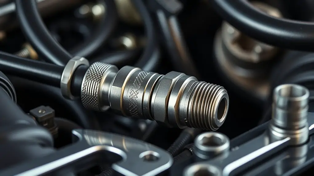
Installing the New Oxygen Sensor Correctly
Installing the new oxygen sensor correctly starts with confirming the sensor type and vehicle requirements, then removing the old unit carefully and preparing the mounting area. You verify the exact part number, then inspect the threads and gasket or O-ring. Clean the mounting hole to remove any residue that could affect seal or readings. When you thread in the new sensor, you’ll follow the manufacturer’s torque specifications to avoid over-tightening or under-tightening, which can cause leaks or poor sensor readings. Use a proper oxygen sensor socket to prevent rounding the hex. After installation, reconnect the sensor wiring securely and leave enough slack for movement without stressing the connector. During insertion, keep the sensor perpendicular to the exhaust flow to maintain accurate readings. For best results, perform sensor alignment tips by aligning the new unit with the exhaust stream and existing downstream sensors. Confirm a smooth idle and monitor for any faulty codes as you complete the procedure.
Wiring and Grounding: Common Pitfalls to Avoid
Wiring and grounding are where many O2 sensor issues originate, so get them right the first time. You’ll want clean, solid connections and a grounded reference that won’t shift with engine load. Start with exact pin alignment and match the vehicle’s harness color codes to avoid cross‑talk. Use new OE‑spec wiring if you’re replacing leads, and check for damaged insulation that could create intermittent faults. During wiring inspections, look for loose crimps, stretched sleeves, and corrosion at connectors. Never assume a single bad wire; trace the circuit to confirm continuity and impedance within spec. Grounding techniques matter: secure a solid metal path to the chassis or engine block, and minimize ground loop resistance by keeping grounds short and direct. Route wires away from heat sources and moving parts to prevent fatigue. Protect against EMI by using proper shields where applicable.
- Confirm pinout accuracy and mating connectors
- Inspect insulation, crimps, and sheath integrity
- Verify continuous, low-resistance grounds
- Route wires away from heat and vibration
- Use shields or sleeves to mitigate EMI
grounding techniques, wiring inspections
Resetting the ECU and Confirming the Fix
After addressing wiring and grounding, the next step is to reset the ECU to clear learned values and run a fresh diagnostic cycle. You’ll perform an ECU reset to erase adaptive memory and guarantee the new O2 sensor data is evaluated without bias. With power restored, reconnect the battery or use the diagnostic tool to initiate a reset, following your vehicle’s procedures. Once the ECU restarts, drive through a controlled cycle: idle, light throttle, steady cruise, and brief acceleration to let the system recalibrate. During initial minutes, you may see erratic readings as the ECU re-learns; don’t panic—this is normal. After a few ignition cycles, pull fresh trouble codes to verify no pending error codes remain. If codes reappear, note them and recheck connections. When the cycle completes, you should have a clean slate and clear visibility into the emissions system’s behavior.
Testing the Vehicle After Replacement and Emissions Check
With the ECU reset complete and fresh data now guiding the system, you’ll start testing the vehicle to confirm the replacement O2 sensor is operating correctly and the emissions checks pass.
- Run a road test at steady throttle to verify the sensor’s response and monitor live data for proper switching
- Verify fuel trims and sensor voltage swings fall within manufacturer specs during post repair checks
- Check for any diagnostic trouble codes related to the O2 system and clear if only pending codes remain
- Confirm readiness monitors complete and emissions readiness shows all systems pass
- Perform a final OBD-II scan to ascertain no new faults emerged after replacement
This approach guarantees testing emissions are accurate, post repair checks verify system integrity, and you maintain control while the vehicle proves its readiness.
Frequently Asked Questions
Can a Bad O2 Sensor Cause High Idle or Stalling?
Yes, a bad O2 sensor can cause high idle or engine stalling. When it sends faulty readings, your engine’s ECU mis-adjusts fuel mixture, leading to erratic idle and possible stalling. You might notice rough starts, hesitation, or fluctuating RPMs. If you’re chasing this, check for diagnostic trouble codes and test the sensor’s performance with proper tools. Replacing a failing sensor usually restores stable idle, smooth running, and reliable, trusted operation.
Should I Replace All O2 Sensors at Once?
No, you don’t have to replace all sensors at once. Replace the failing unit, then monitor others for sensor lifespan signs. Consider cost considerations and your budget, since replacing multiple sensors can add up quickly. In many cases, one sensor failure doesn’t imply the rest are bad. Stay proactive: check diagnostics, review monitor readiness, and plan replacements as needed to keep emissions compliant and performance optimized.
How Long Does a Cold-Start O2 Sensor Take to Heat Up?
A cold-start O2 sensor typically takes about 30 seconds to a minute to heat up to its operating range. You’ll notice the sensor heating as the exhaust warms and the engine codes stabilize. In cold ambient temps, expect the longer end of that range. The key is the sensor reaching its light-off temperature quickly, so idle stability improves. Track warm-up with after-start decline in fuel trim, not just gauge readings.
Can Faulty Wiring Mimic a Bad Sensor Reading?
Yes, faulty wiring can mimic a bad sensor reading. You may see erratic or out-of-range signals, confusing sensor diagnostics, and an inflated or inconsistent fuel trim. Inspect harnesses, connectors, and grounds for corrosion, cracks, or pin looseness. Use a scan tool to compare sensor data against expected ranges, verify continuity, and rule out voltage drops. Address wiring issues promptly to avoid misdiagnosis and guarantee accurate emissions readings.
Is a Universal O2 Sensor Compatible With My Vehicle?
Yes, a universal O2 sensor can work in many setups, but compatibility isn’t universal. An example: your late-model sedan uses a narrowband sensor, so a universal option must match the sensor type and wiring. Know your vehicle sensor types and verify connector, heater, and signal ranges. Check compatibility with the vehicle’s ECU. If it fits, you gain flexibility; if not, you risk inaccurate readings and additional emissions issues. Always confirm universal sensor compatibility before buying.