Step-By-Step: Replacing Regulator to Solve Inconsistent Voltage Under Load
Start by identifying symptoms like dimming, flicker, or unstable gauges, then measure input and output voltages under representative load with a calibrated multimeter and oscilloscope. Check grounding, connectors, and harness continuity, isolating the regulator from the load if needed. Locate the regulator type (linear, switching, LDO) and document deviations, ripple, or noise. If needed, replace it with a component that matches electrical ratings, torque mounting, and safety procedures, then verify performance and protection features—more steps await.
Diagnosing Symptoms and Initial Checks
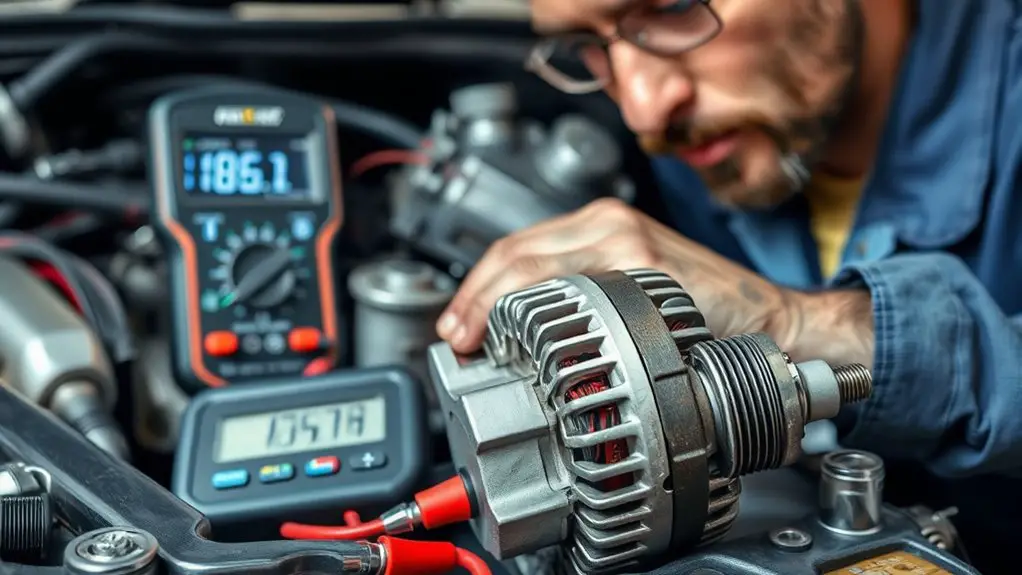
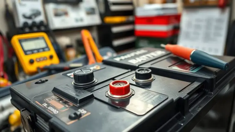
Diagnosing symptoms and performing initial checks is the essential first step in replacing a regulator for voltage issues. You approach the task with deliberate focus, documenting observable signs and establishing a baseline. Start with symptom identification: note any report of dimming lights, flickering indicators, or erratic gauge behavior. Next, assess voltage fluctuation across key nodes while the system runs at nominal load, recording values at the regulator input and output. Use a calibrated multimeter and, if available, an oscilloscope to detect ripple or transient spikes beyond acceptable tolerance. Verify load stability by simulating typical operating conditions and observing responses over a defined interval. Confirm grounding integrity, connector seating, and harness continuity to prevent false positives. Compare measurements against manufacturer specifications and historical data, distinguishing intermittent faults from steady-state abnormalities. If symptoms persist, plan a controlled shutdown for safe reevaluation, ensuring you preserve evidence for subsequent diagnostic steps and potential component testing. Maintain coherence, precision, and purposeful documentation throughout.
Tools, Safety, and Preparation
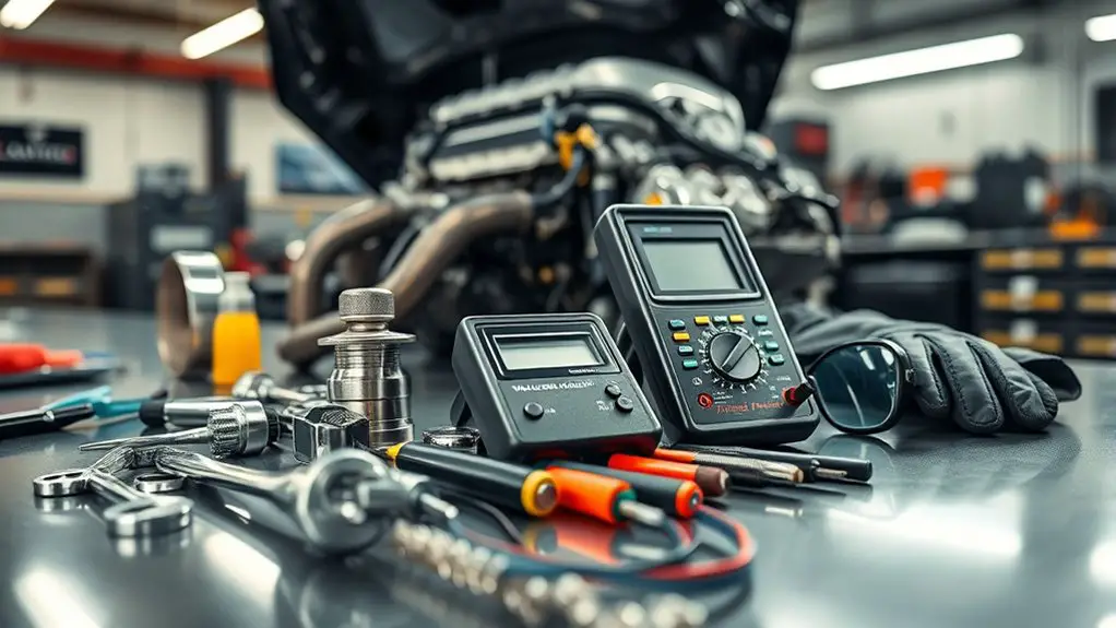
Before touching the system, assemble the required tools and PPE and verify that your workspace is prepared for a controlled procedure; this minimizes downtime and reduces risk to personnel and equipment. You’ll rely on calibrated multimeter, insulated wrenches, torque screwdriver, torque range chart, and replacement regulator. Have a thermal imaging tool for hot spots and a portable bench power supply for testing in isolation. Prepare isolation barriers, flashlight, and a clean nonconductive work surface. Safety equipment includes eye protection, cut-resistant gloves, and a flame-resistant sleeve if nearby soldering is possible. Establish a preparation checklist to confirm tool integrity, battery status, and device grounding. Label components to prevent mix-ups, and document parameter baselines before any removal. Maintain a tidy work area to avoid accidental contact with energized parts. Verify that emergency stop access remains unobstructed, and communicate planned steps to nearby personnel to support controlled, deliberate action. This approach minimizes risk while preserving diagnostic momentum.
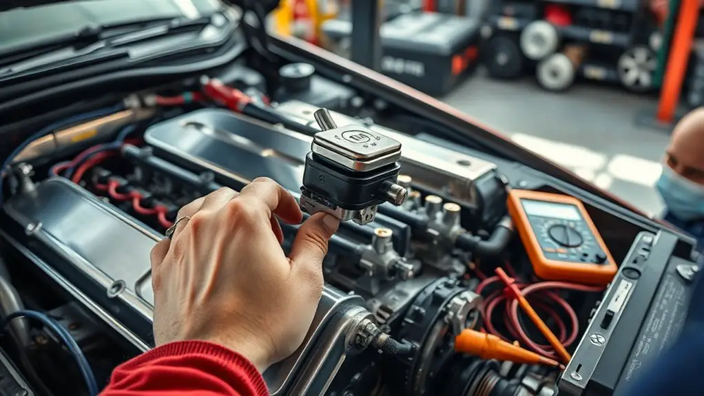
Locating and Testing the Regulator
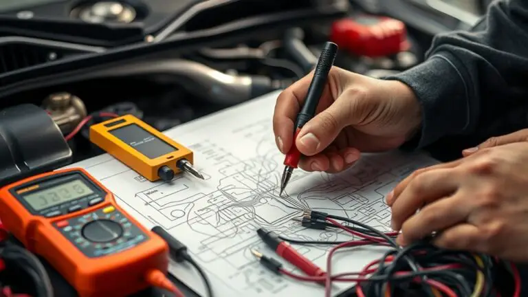
Locating the regulator begins with a careful, system-wide scan to identify where regulation occurs and how it interfaces with power delivery. You’ll map power paths from the source through distribution, noting nodes where voltage is monitored and adjusted. Focus on regulator types present in the design, distinguishing linear, switching, and LDO variants, plus any early-stage protection devices that influence regulation. Use objective measurements to separate supply rails, reference networks, and feedback loops from load interactions. For testing, perform a controlled voltage baseline at the input and at critical nodes under representative load conditions. Document any deviations, noise, or ripple that may indicate regulator interference. When you conduct voltage testing, employ appropriate instrumentation, verify ground references, and confirm stability with transient and steady-state tests. Keep the testing sequence repeatable, repeatable, and traceable to the schematic. This methodical approach clarifies whether regulation aligns with design intent before you proceed to replacement considerations.
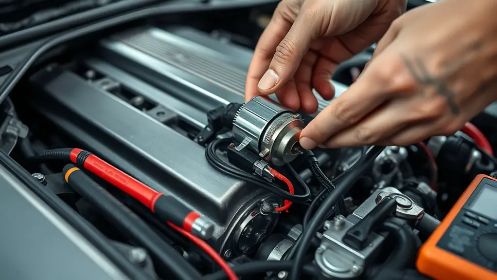
Replacing the Regulator: Step-by-Step
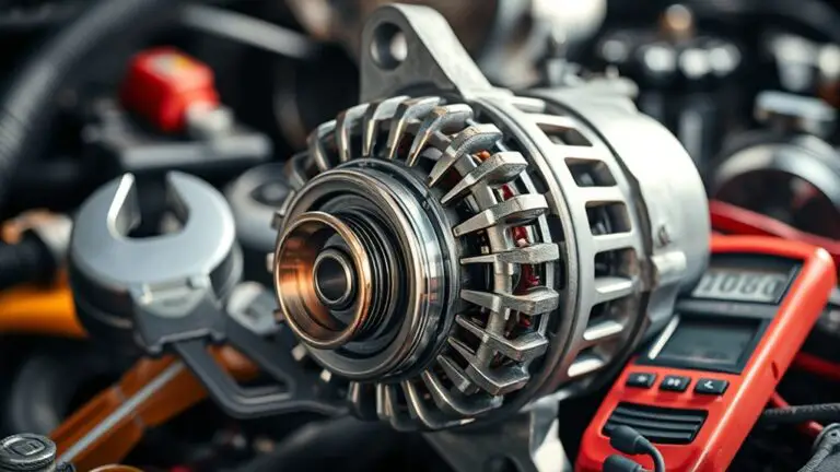
Replacing the regulator involves a controlled, methodical swap that preserves circuit integrity and minimizes disruption to load regulation. You’ll approach this in clear steps, verifying compatibility, safely powering down, and documenting any deviations from nominal behavior. Begin by isolating the section, noting regulator types, and confirming the replacement’s electrical ratings align with your system’s voltage stability needs. Disconnect input, ground, and output with proper PPE, then remove the existing unit without stressing adjacent components. Install the new regulator flush, torque mounting hardware to spec, and reattach wiring precisely as labeled. Reapply power gradually, monitoring for expected voltage regulation changes and transient responses. If readings diverge, revisit connections and verify heat sinking remains adequate for sustained operation. Table below aids quick reference during the swap.
| Step | Focus |
|---|---|
| Safety | PPE and de-energization |
| Verification | Ratings and wire routing |
Verification and Post-Install Validation
After swapping the regulator, you’ll proceed with Verification and Post-Install Validation to affirm proper operation and identify any issues early. This phase emphasizes repeatable, objective checks that prove stability under load. Initiate verification techniques that cover electrical, thermal, and transient behavior, documenting baseline readings for voltage, current, and regulator temperature. Use precise measurement tools: multimeters, oscilloscopes, and data loggers, with timestamped results and pass/fail criteria defined beforehand. Conduct steady-state checks at multiple load points to ascertain voltage remains within spec and responds predictably to load changes. Perform short-term and extended burn-in to reveal intermittent faults. Verify protection features, such as overcurrent and thermal shutoff, engage correctly and reset as intended. Validate wiring integrity, connector seating, and absence of parasitics that could induce oscillation. Conclude with post installation testing to confirm system performance aligns with design goals, and prepare a concise report detailing any deviations and corrective actions.
Frequently Asked Questions
Will Regulator Replacement Affect Warranty Coverage or Returns?
Warranty coverage typically isn’t voided by a regulator replacement if the work is performed properly and within your device’s stated warranty terms. However, warranty limitations and return policies vary by manufacturer and region, so consult your coverage specifics. If the replacement is done by an authorized technician, you’re more likely to retain coverage; DIY work may trigger exclusions. Before proceeding, verify warranty limitations, document procedures, and retain receipts to support any future returns or claims.
Can Load-Induced Failures Cause Intermittent Regulator Issues?
Yes, load variations can cause intermittent regulator issues, especially when voltage spikes occur under heavy demand. If you see erratic output, you’re likely dealing with transient stress or insufficient headroom in the regulator’s supply. Monitor for sudden voltage spikes during load swings, then verify input filtering, thermal management, and component tolerance. A methodical diagnostic helps you isolate whether the instability stems from load-induced stress or an upstream supply limit.
Are There Alternative Fixes to Consider Before Replacement?
Yes, there are alternative fixes to contemplate before replacement. You should inspect voltage stabilization paths and verify proper grounding, routing, and load balance. Try capacitor upgrades to smooth transient spikes, replace dried or leaky filter caps, and review regulator input/output capacitance per specs. Re-check wiring, ferrite cores, and PCB traces for impedance issues. Document measurements, then retest under load. If instability persists, proceed with regulator replacement as a final, data-driven step.
How Do Ambient Temperature Changes Impact Regulator Performance?
Ambient temperature directly affects regulator performance by altering component spread, thermal resistance, and MOSFET switching behavior. As temperatures rise, you’ll see slower response, higher dropout, and potential regulation drift; cooler conditions improve accuracy but risk condensation effects on edges. You should monitor with thermistors, bias networks, and proper heatsinking. In practice, you verify ambient temperature remains within spec, assess heat dissipation, and adjust compensation or layout to maintain stable regulator performance under varying environmental conditions.
What Safety Precautions Exist for Non-Electrical Personnel?
Could you take safety seriously when working around electrical systems? You should wear appropriate personal protective equipment and maintain electrical hazard awareness at all times. As a non-electrical person, you’ll follow strict, documented procedures, avoid touching live components, and stay clear of exposed conductors. Keep a safe distance, use insulated tools, and verify lockout/tagout is in place. Report any abnormalities immediately, and never bypass safety controls. Your preparation protects you and others.