Step-By-Step: Replacing a Broken LED Module
To replace a broken LED module, start by powering down at the breaker, verify no voltage with a non-contact tester, and document the current wiring. Inspect for damage, load specs, and mounting compatibility. Remove the faulty module, noting shims, brackets, and connectors, then test continuity and polarity before installing the new unit. Align the module, secure fasteners evenly, and reseat all connectors. Perform a low-power burn-in and full test; follow steps closely to avoid latent faults—more specifics await.
Diagnosing the LED Module Failure
To diagnose a broken LED module, start with a visual and tactile inspection for obvious damage such as cracked lenses, burnt components, or swollen capacitors. You evaluate exterior integrity, then examine solder joints for cold joints or cracks. Next, document observable symptoms completely, because accurate symptoms analysis guides targeted testing. Move to electrical checks: verify supply voltage matches the module’s rating, and confirm polarity isn’t reversed. If the module powers briefly or flickers, note timing and brightness changes as part of your symptoms analysis. Measure voltage at the input and across individual LEDs or strings, looking for drops outside tolerance. Compare readings to the rated specifications and, if available, reference design curves. Consider thermal conditions, since excessive heat can mimic or mask failures. Record all measurements methodically, maintaining a clear chain of custody for later diagnostics. Logical, repeatable steps reduce uncertainty and support a precise conclusion about the failure mode.
Tools and Safety Gear You’ll Need

You’ll start by gathering PPE and safety gear to protect yourself from electrical hazards and sharp components. Next, assemble essential hand tools and verify they’re in good condition for precise removal and installation. Throughout the task, follow safe working practices to minimize risk and guarantee a clean, repeatable process.
PPE and Safety Gear
PPE and safety gear are essential when replacing a broken LED module. You should select appropriate items before you start, aligning protection with the task steps. Personal protective gear types include eye protection, gloves, and a lab coat or apron to shield skin and garments from sharp edges, flux, or solder splash. Use safety glasses or goggles to guard against debris, and consider a face shield if you’ll work with hot solder or projecting fragments. Nitrile gloves offer chemical resistance and tactile control, while cut-resistant options protect hands during removal. Ascertain footwear is closed-toe and non-slip. Keep a tidy workspace with a spill kit and a dedicated waste container for damaged components. Confirm all PPE is fitted, intact, and compliant with local safety standards.
Essential Hand Tools
Essential hand tools are the backbone of a safe, efficient LED module replacement. You’ll want a compact screwdriver kit, a fine-tibered multimeter, and precision pliers to handle small fasteners without damage. Keep a magnetic tray to prevent loss of screws and a non-conductive lookup to verify connections. A utility knife, snips, and a wire stripper lend flexibility for minor wiring tasks, while insulated gloves protect against unexpected contact. Plan tool layout before you begin to minimize motion and errors. Hand tool selection should emphasize grips that fit your hand and predictable torque. Regular tool maintenance keeps accuracy high: clean tips, inspect blades for nicks, and test meters before use. Your setup should promote control, efficiency, and freedom to work confidently.
Safe Working Practices
To work safely, you should start with the right protective gear and tools, then ascertain the work environment is ready for a LED module replacement. You’ll wear gloves, eye protection, and a non-conductive mat; you’ll power down and lock out energy sources. Use insulated tools, proper RTDs, and a multimeter to verify de-energization. Maintain clear work zones and label components to support electrical safety and personal responsibility. Plan each step, minimize motion, and test after reassembly. Remember to document deviations and communicate risk.
| Step | Action | Rationale |
|---|---|---|
| 1 | Power down | Prevent shock and arc flash |
| 2 | Inspect PPE | Ascertain protection remains intact |
| 3 | Verify isolation | Confirm no residual energy |
| 4 | Use correct tools | Avoid damage and injury |
| 5 | Test function | Validate safe operation |
Accessing the Fixture and Gaining Power
Accessing the fixture and gaining power begins with safety and organization: confirm the power is off at the breaker, then locate the fixture’s access panel or canopy. You’ll plan your approach by noting nearby power sources and the route to the switch. Use a non-contact tester to verify no voltage at exposed conductors before touching any hardware. Gather the necessary tools and keep them organized in a labeled pouch to prevent crossed wires or tool misplacement. If the fixture is mounted high, secure a stable working platform and avoid overreaching. Disconnect the power leads only after you’ve confirmed de-energization, and cap any open conductors to prevent accidental contact. Document the current wiring arrangement for reference. When initiating fixture access, minimize movement to avoid disturbing other components. Maintain awareness of heat sinks, ballast, and alignment constraints, and plan reassembly with deliberate, orderly steps. This careful preparation streamlines safe restoration and preserves future power sources.
Identifying a Compatible Replacement
You start by checking the LED specs to guarantee voltage, current, and lumen output match the existing module. Next, compare electrical fit and connector type to avoid compatibility issues, and verify mounting style to match the fixture. Finally, confirm the replacement’s form factor and ensure it aligns with space and mounting hardware before proceeding.
Check LED Specs
When replacing a broken LED module, start by confirming the exact LED specifications of the unit you’re working with. Identify the LED wattage, color temperature, and form factor from the label or schematic. Note whether the module uses a constant current driver or a fixed voltage supply, and record the acceptable tolerances. Verify the LED type (SMD, COB, or array) and any binning information that could affect brightness and color. Check forward voltage and current ratings to ascertain compatibility with your driver. Inspect the thermal design and mounting hardware to match the replacement’s dimensions. Cross-check compatibility with the existing optics, lens, and power connector. Document these specs for future reference to prevent mismatches and guarantee reliable performance.
Compare Electrical Fit
To identify a compatible replacement, start by comparing the electrical specs of the existing module with the candidate: forward voltage range, current rating, and power dissipation. This is a compatibility assessment, not a guess. You’ll map exact electrical specifications to guarantee predictable performance and thermal behavior. Proceed with a side‑by‑side check, noting any deviations and their potential impact on brightness and lifespan. If the candidate matches within tolerance, you gain freedom from uncertainty; if not, you refine choices until alignment is true.
| Dimension | Existing | Candidate |
|---|---|---|
| Forward voltage | 2.8–3.2 V | 2.9–3.1 V |
| Current rating | 20 mA | 20 mA |
| Power dissipation | 60 mW | 60 mW |
Confirm Mounting Type
Confirming mounting type is essential before selecting a replacement because an incompatible mount can prevent installation or misalign electrical and optical performance. You’ll verify mounting type first, then compare to the new module’s interface, gaps, and anti-rotation features. Prioritize precise fit over cosmetic similarity to guarantee fixture compatibility and safe operation. Document the exact mounting pattern, screw size, and bracket style, then cross-check with the replacement’s spec sheet. If needed, consider adaptable mounting brackets or a retrofit kit that preserves alignment. Confirming early saves time and preserves performance, illumination quality, and warranty terms. Proceed to match mechanical and electrical interfaces before procurement.
- Mounting brackets: confirm pattern, screws, and load rating
- Fixture compatibility: verify interface, depth, and clearance
- Retrofit options: assess brackets, adapters, and safe mounting tolerance
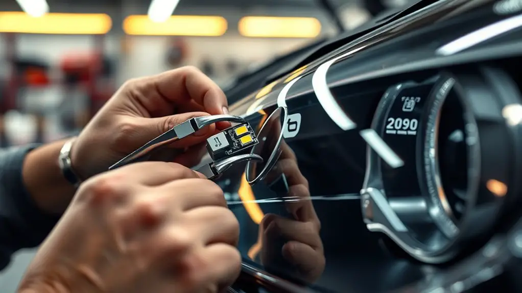
Removing the Faulty LED Module
Begin by powering down and disconnecting the device, then locate the faulty LED module at its mounting points. You’ll approach removal with controlled, deliberate steps to preserve surrounding components. Identify fasteners, connectors, and any anti-tamper features that secure the module to the chassis or heat sink. Use the appropriate tool set—authentic drivers, spudgers, and terminal release clips—without forcing parts. Disconnect power-sensitive cables first, keeping them labeled to prevent mix-ups during reassembly. Gently separate the module from its seating, noting any shims or alignment guides. If a bracket or screws show corrosion, document their condition for warranty or replacement decisions. Avoid prying against fragile circuit traces or heat-dissipation surfaces. Manage the removed module as a separate assembly, placing it on an anti-static surface. This phase centers on faulty module removal and careful LED fixture disassembly, establishing a clean, referenceable baseline for the subsequent replacement procedure.
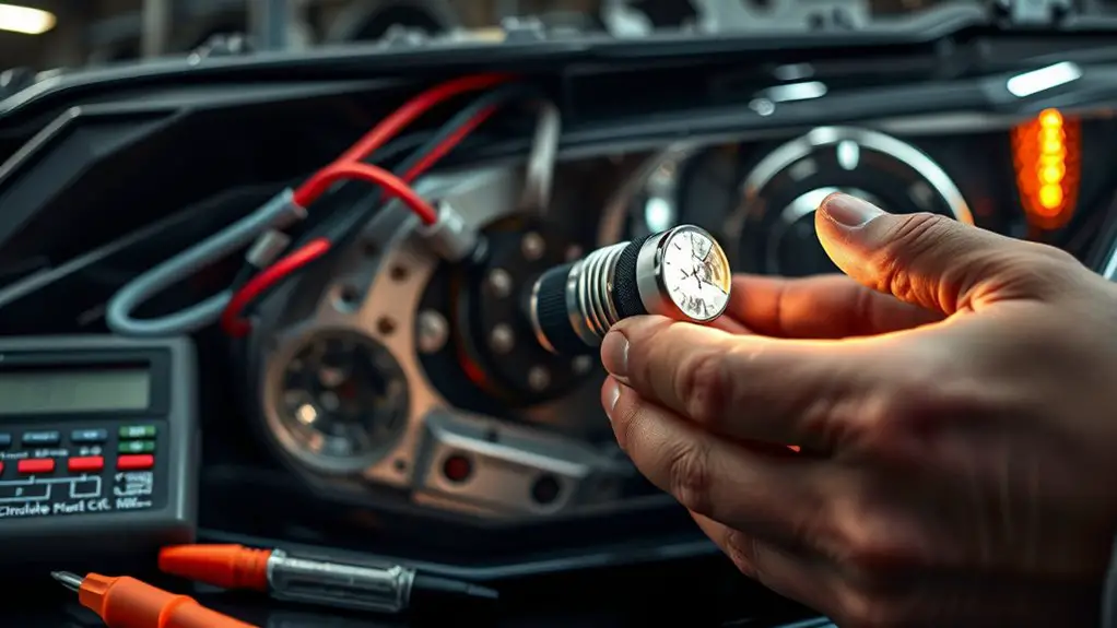
Wiring and Connection Check
- You’ll verify every lead before powering up, focusing on safe, precise checks that won’t waste time or force a redo.
- wiring diagrams you’ve reviewed guarantee correct polarity and routing
- connection tips like clean terminals, tight crimps, and strain relief
- measured continuity paths that confirm a complete circuit without shorts
Begin by inspecting the harness and PCB traces for damage or corrosion. Compare actual wiring to the wiring diagrams; verify wire gauges and connector types match the spec. Check power and ground lines first, then signal lines if applicable. Ascertain all connectors click firmly and seats are fully seated, with any locking tabs engaged. Look for stray conductive debris, lifted pads, or bent pins, and address them before testing. Use a multimeter to confirm continuity and verify no short circuits between power and ground. If anything deviates from the diagram, pause and reassess before moving forward. This upfront diligence prevents faults in later steps and preserves system reliability.
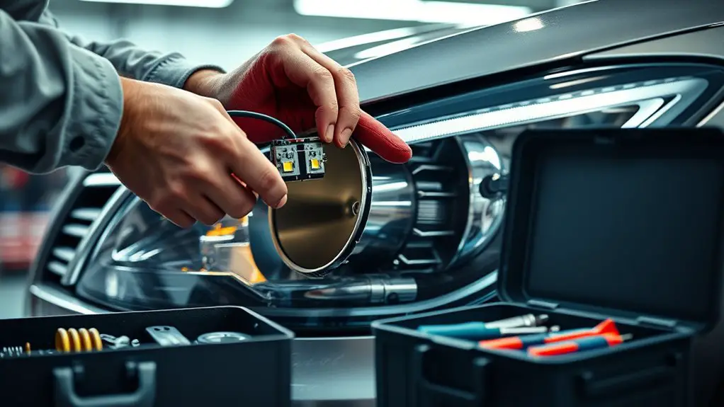
Installing the New LED Module
With the new LED module in hand, align it to the mounting surface and seated connectors, ensuring the orientation matches the device’s specification. You’ll verify polarity and fit before any attachment. Position the module so the electrical pads mate cleanly with the board traces, avoiding contact with metal edges. Secure it using the prescribed fasteners or clips, tightening evenly to prevent stress on connectors. If the design uses a snap-in or z-axis retainer, seat it firmly until you hear a definitive click. Recheck alignment after initial seating to confirm there’s no tilt that could foul optical elements or cooling paths. Consider the variety of led module types you may encounter, and apply the appropriate installation techniques for each configuration, including connector shrouds, gasket seals, or heat-sinking interfaces. Document any deviations from the standard layout for future reference. Once secured, perform a light inspection for foreign debris and confirm that electrical isolation remains intact prior to power-up.
Testing and Final Troubleshooting
After securing the new LED module, initiate a structured testing sequence to verify operation and identify faults before full power-up. You’ll perform final checks in a disciplined order, confirming wiring integrity, solder joints, and connector seating. Observe polarity, current limits, and driver compatibility, then run a low-power burn-in to surface latent defects. Document measurements for a clear performance evaluation, and halt if any deviation appears. If screens glow unevenly or flicker, recheck seat and grounding paths, then re-test. Use a multimeter to verify continuity and diode orientation, and confirm thermal interface contact remains solid after reassembly. Ascertain safety interlocks are engaged, and power is applied through the proper supply profile. Record final tests outcomes, tag the module, and proceed to full-power validation only when results meet specification.
- Thorough wiring and polarity verification
- Low-power burn-in and defect detection
- Documentation and performance evaluation results
Frequently Asked Questions
How Long Does a LED Module Replacement Typically Take?
Replacement time for a LED module replacement is typically 30 to 60 minutes, depending on module complexity. You’ll disconnect power, remove the faulty unit, and install the new module with proper polarity and secure connections. Expect a brief calibration or testing phase to confirm brightness and color. This task is precise and methodical, but you value freedom, so take your time to verify each step. If you’re experienced, you’ll finish efficiently without compromising safety or performance.
Can I Replace Just the LED Module or Entire Strip?
Yes—you can replace just the LED module if the rest of the strip and drivers are compatible. Check LED module compatibility with your existing strip’s voltage, current, and pinout. Assess cost considerations: replacing only the module is usually cheaper, but mismatches can force a full strip swap. Verify driver compatibility and dimming behavior, and confirm heat sinking remains adequate. If in doubt, compare total costs and performance before proceeding.
Will Replacement Affect Fixture Warranty or Insurance?
Replacement can impact warranty and insurance, but it varies by policy and maker. You’ll want to check the exact terms: some warranties cover only original modules and require professional installation, while others allow component swaps without voiding coverage. Juxtapose risk with reward: you gain flexibility, yet you might lose protections. For warranty implications and insurance coverage, confirm documentation, retain receipts, and document the replacement details. If in doubt, consult the vendor or insurer before proceeding.
Are Dimming Capabilities Preserved With a New Module?
Dimming capabilities depend on the replacement’s dimming technology and module compatibility. If the new module supports the same dimming protocol, you’ll preserve dimming performance. Verify that the replacement uses compatible dimming technology and matches your driver specifications. If not, dimming may be degraded or lost. Ascertain module compatibility with your fixture’s controller and driver range to maintain smooth, flicker-free operation. Test thoroughly after install to confirm consistent dimming behavior across adjustments.
What Signs Indicate Failure Beyond Illumination Loss?
Like a compass needle wavering, you’ll notice signs beyond illumination loss. You’ll see flickering lights, intermittent brightness, or color shift as indicators of failure. Inspect for dimming with inconsistent color temperature, buzzing, overheating, or odd capacitor heat. Corrosion, connector looseness, or degraded phosphor can signal gain or driver issues. If you observe these patterns, plan a module test, verify driver compatibility, and replace the module to restore stable, predictable performance for your free-minded setup.