Step-By-Step: Using a Manufacturer-Level Scan Tool to Diagnose Faulty Aftermarket Modules
To diagnose faulty aftermarket modules with a manufacturer-level scan tool, first gather the proper tool, safety gear, and OEM guidance. Verify vehicle compatibility and module fitment, then establish a stable baseline by locking onto the correct ECU and enabling the needed PIDs. Pull live data, note baselines, and compare against factory specs. Identify DTCs, distinguish intermittent from permanent codes, and perform targeted tests to isolate the failing module. You’ll uncover precise steps as you proceed.
Gathering the Right Tools and Safety Procedures
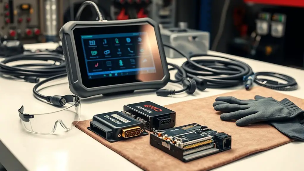
Gathering the right tools and safety procedures begins with a concise plan. You establish a clear scope, identifying the diagnostic tasks you’ll perform and the environment you’ll work in. Next, assemble safety gear and reference manufacturer guidance to minimize risk. You’ll select a primary scan tool compatible with the OEM interface, plus any required adapters, power supplies, and data cables. Keep a backup battery, a multimeter, and a scope-capable module if you anticipate waveform checks. Tool organization matters: lay out items in a logical workflow, label connectors, and store small parts in a case that seals against dust and moisture. Verify calibration status and firmware versions before connecting to the vehicle network. Maintain a clean bench, free of conductive debris, to prevent shorts. Finally, document the exact tools used and procedures followed for reproducibility and traceability. This disciplined setup supports precise, repeatable diagnostics while preserving freedom to adapt. safety gear is essential throughout.
Understanding Manufacturer-Level Scan Tools and Protocols
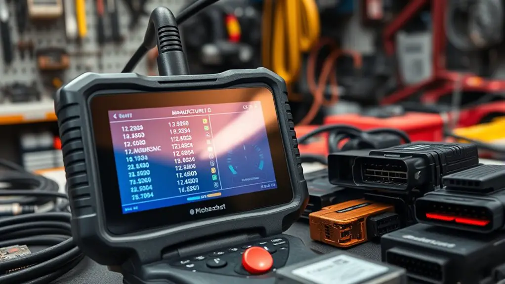
Manufacturer-level scan tools provide access to OEM-specific interfaces, protocols, and calibration data that generic scanners can’t reveal. You’ll navigate manufacturer protocols to access unique controllers, interpret fault codes, and read live data streams with authoritative context. This precision keeps your workflow efficient and your edge uncompromised.
- Understand scan tool features that grant access to OEM routers, vendor IDs, and access permissions for specialized modules.
- Map each protocol to its data formats, message timing, and safety guards so you can interpret results without guessing.
- Verify that the tool’s calibration data and software licenses are current to maintain reliability and legal compliance.
To maximize freedom within a controlled process, you’ll align your diagnostic steps with documented manufacturer protocols, ensuring repeatable outcomes. Focus on clear data interpretation, avoid speculative conclusions, and document each observation. Your aim is accurate fault isolation, leveraging scan tool features while honoring system integrity and warranty considerations.
Verifying Vehicle Compatibility With Aftermarket Modules

Before attempting any aftermarket installations, verify that the vehicle and the module are compatible by cross-checking manufacturer specifications, repair data, and service bulletins to avoid voiding warranties or triggering safety issues. You’ll assess fitment at the system level, not just the connector. Begin by mapping relevant vehicle system functions to the module’s capabilities, noting inputs, outputs, communication protocols, and power requirements. Confirm that the aftermarket module compatibility aligns with OEM design limits, protection schemes, and fault-handling logic. Review electrical parasitics, grounding schemes, and CAN bus arbitration to prevent message conflicts. Check for mandated immobilizer or security integrations and verify software versions support both ends of the exchange. Validate service data and dealer advisories for any known compatibility cautions. Document compatibility decisions with exact references to repair data and bulletins. Only after these checks, proceed with controlled bench testing and staged in-vehicle verification to guarantee seamless vehicle system integration.
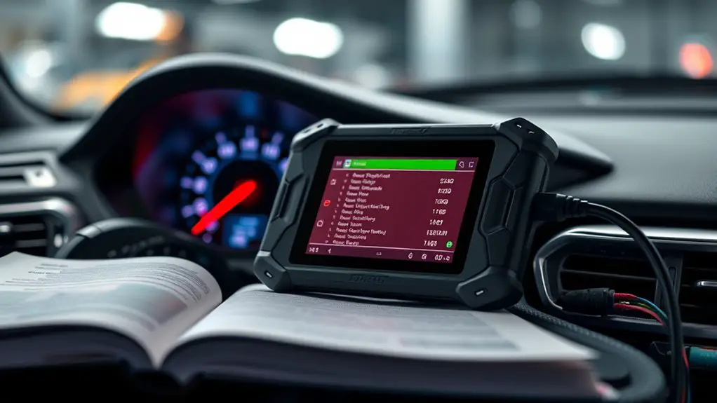
Accessing On-Board Diagnostics and Live Data Streams
Accessing On-Board Diagnostics (OBD) and live data streams requires a systematic approach to guarantee accurate readings and safe integration. You’ll focus on direct access to the diagnostic stream and guard against data noise that can mislead fault identification. Precision comes from filtering for relevant PIDs, confirming unit compatibility, and syncing tool timestamps with vehicle activity to preserve context.
Access OBD data with focused PID filtering, unit checks, and synchronized timestamps to separate signal from noise.
1) Establish a stable baseline by locking the tool to the correct ECU and enabling only the necessary PIDs for live data interpretation.
2) Confirm data integrity by cross-checking readings against known-good ranges, watching for packet loss, and validating steering, braking, and powertrain signals under load.
3) Document measurements with timestamped logs, then correlate transient spikes to ignition events or sensor state changes for reliable diagnostic stream analysis.
Use this approach to separate signal from noise, ensuring you interpret live data with clarity and confidence.
Recording Baseline Readings Before Intervention
To start recording baseline readings, you’ll first establish a reference frame that reflects normal operating conditions. You’ll capture stable, repeatable metrics from the OEM scan tool across relevant channels, such as voltage, current, sensor values, and controller responses. Document the exact vehicle state, including engine temperature, load, and RPM, before any intervention. Use consistent sampling intervals and logging duration to guarantee data integrity. Create a controlled baseline by recording multiple cycles of normal operation, then compute averages and variability for key parameters. This baseline enables a precise baseline comparison later, highlighting deviations caused by aftermarket modules. Maintain meticulous timestamps and unit conventions, and verify data consistency across sessions by cross-checking against known-good values from manufacturer references. Store readings in a centralized, accessible format with version identifiers. Avoid introducing nonessential variables; focus on metrics that reflect functional, legitimate operation. The goal is a reliable, repeatable reference for subsequent diagnosis and comparison.
Identifying Common Fault Codes Related to Aftermarket Modules
You’ll start by reviewing common P-Codes specific to aftermarket modules to distinguish calibration, communication, and compatibility issues. Next, you’ll summarize the Diagnostic Trouble Codes (DTCs) landscape, noting which codes are most frequently triggered by non-OEM additions and how they map to subsystem faults. Finally, you’ll compare intermittent versus permanent codes to plan targeted verification steps and determine appropriate corrective actions.
Common P-Codes for Aftermarket Modules
Common P-codes encountered with aftermarket modules tend to indicate interface or compatibility issues, sensor wiring faults, or improper integration with the vehicle’s ECU. You approach troubleshooting with a disciplined mindset: isolate whether a module’s signals align with OEM expectations, verify power and grounding integrity, and confirm software/firmware revisions. Expect codes that reflect signal integrity, communication handshakes, and channel errors, rather than broad electrical faults alone. Use the codes to map fault origins to core subsystem interfaces, not as final adjudicators of module failure. Prioritize diagnostic steps that validate aftermarket compatibility and assess module performance under tested conditions.
1) Code interpretation focused on interface compatibility and timing mismatches
2) Codes indicating sensor or bus wiring faults affecting data integrity
3) Codes tied to ECU communication and module handshake failures
Diagnostic Trouble Codes (DTCs) Overview
Diagnostic Trouble Codes (DTCs) for aftermarket modules tend to cluster around interface and timing issues, sensor data integrity, and ECU communication handshakes rather than generic electrical faults. In this overview, you’ll map DTC categories to failure modes you’re likely to see during diagnostics. Focus on how codes reflect data flow, polling latency, and handshake acknowledgments between the module and the ECU. Prioritize codes by relevance to aftermarket interfacing, then apply code prioritization to sequence your troubleshooting steps. You’ll classify codes by origin (communication, sensor, timing) and by impact (system stability, data validity, control authority). This approach reduces noise, accelerates diagnosis, and clarifies needed repairs. Remember to document observed patterns and correlate them with test results for robust, repeatable outcomes.
Intermittent Vs Permanent Codes Detection
Intermittent fault codes appear sporadically, reflecting fluctuating data integrity, unstable communication timing, or handshake variability between aftermarket modules and the ECU. You’ll want to distinguish intermittent codes from permanent codes by monitoring persistence across cycles and session logs, then correlating with module exchange events and wiring integrity. The goal is to lock down root cause without chasing noise.
- Compare intermittent codes against stored permanent codes after power cycling and reboot tests.
- Cross-check timing-sensitive frames, baud rates, and diagnostic readiness to confirm reproducibility.
- Validate module-to-ECU handshakes under load, and verify that intermittent codes resolve when the aftermarket module is isolated.
This methodical approach yields clear, actionable results while preserving diagnostic freedom.
Interpreting Live Data to Pinpoint Module Faults
When you interpret live data, you’re comparing real-time sensor readings, fault codes, and module statuses to expected ranges to identify where a fault originates. You’ll map data trends over time, noting deviations, spikes, or lag between inputs and outputs. Start with baseline values for each module, then watch for concordance or discordance between related signals—e.g., sensor voltage versus commanded behavior. Prioritize anomalies that consistently appear across cycles and vehicle conditions, not isolated blips. Use filters to suppress noise, then validate with cross-channel correlation: matching patterns across input, output, and fault code histories strengthen a fault hypothesis. Keep focus on actionable indicators of module performance, such as unexpected duty cycles, abnormal temperature shifts, or delayed response times. Document findings with timestamps, parameter names, and threshold references. This disciplined approach yields a concise, data-driven view that guides decisions without overreach. live data analysis supports precise diagnostics and informed module-level troubleshooting.
Isolating Faulty Modules With Targeted Tests
You’ll start by outlining targeted test methods to pinpoint faulty modules with precision. Use controlled stimuli and observables to isolate faults without broad system disruption. This approach focuses on isolating modules through systematic, repeatable checks that confirm or refute each candidate component.
Targeted Test Methods
Targeted test methods isolate faults by focusing on specific subsystems or modules and validating their behavior under controlled conditions. You apply structured checks to confirm compatibility, timing, and data integrity, keeping the scope narrow to reveal deviations quickly. Stay objective: document results, compare against expected benchmarks, and proceed only when criteria are met. This approach emphasizes repeatability and clear pass/fail decisions, enabling precise module evaluation through repeatable stimuli and measurable outputs.
- Execute subsystem-specific tests with known-good references to establish baselines.
- Capture real-time data streams and compare timing, responses, and error codes against thresholds.
- Verify fail-safes, fallbacks, and recovery paths under controlled perturbations to confirm resilience.
Isolate Faulty Modules
Isolating faulty modules hinges on applying targeted tests to narrow the fault’s source without escalating scope. You methodically select tests that isolate functions, cross-checking inputs and outputs against expected module performance. Begin with a baseline comparison: record normal behavior, then trigger the same conditions to observe deviations. Use the diagnostic strategy to map symptoms to responsible subsystems, avoiding broad assumptions. If a single module fails a focused test, seal the conclusion with repeatable verification before proceeding. Document every step, including test conditions, tool readings, and time stamps, so trends emerge quickly. When results are inconclusive, refine tests to isolate boundaries, not expand coverage. Maintain minimal invasiveness; preserve module integrity while extracting decisive evidence. This disciplined approach yields precise, actionable insights.
Documenting Findings and Planning Corrective Actions
Documenting findings and planning corrective actions starts with clear, structured notes. You’ll capture fault codes, module IDs, and test results in a concise log, ensuring traceability from symptom to remedy. Your findings analysis should separate observed behavior from inferences, preserving evidence for later validation. Document timestamps, tools used, and any calibration or procedure deviations, so you can reproduce the workflow if needed. From there, outline corrective strategies that align with the diagnostic goals: verify, isolate, and validate changes before finalizing actions. Your plan should balance speed with reliability, prioritizing safe, effective resolutions over quick fixes.
1) Summarize the root cause hypothesis, proposed corrective strategies, and success criteria.
2) List steps to implement changes, including verification tests and acceptance thresholds.
3) Define rollback or containment measures if results don’t meet expectations.
Best Practices to Prevent Misdiagnosis and Future Issues
You should follow Consistent Diagnostic Protocols and apply Documentation and Verification at every step to reduce misdiagnosis and future issues. By standardizing the sequence, you guarantee repeatable results and clearer handoffs between tools and technicians. Maintain concise, verifiable records that support traceability and ongoing accuracy.
Consistent Diagnostic Protocols
Consistent diagnostic protocols minimize misdiagnosis by unifying steps, data collection, and decision criteria across the repair process. You achieve this through a consistent protocol implementation that enforces repeatable sequences, validated data sources, and objective accept/reject thresholds. A systematic diagnostic approach reduces variability and accelerates accurate conclusions, enabling you to compare results over time and across modules. Follow defined entry criteria, standardized test suites, and clear escalation paths to prevent scope creep. Keep records tight and actions auditable to support future work without rework. Align tool configuration, data interpretation, and reporting with the same framework for every case, every time.
- Establish entry criteria and baseline data before testing.
- Use a fixed sequence of tests with predefined pass/fail criteria.
- Document results and decisions concisely for traceability.
Documentation and Verification
To prevent misdiagnosis and future issues, you should pair each diagnostic step with rigorous documentation and verification. Documentation strategies guide every observation, wiring diagram, and tool setting, ensuring traceability. You’ll record timestamps, module IDs, and sensor states, then confirm results with independent checks. Verification techniques include re-testing after each change, cross-referencing live data, and validating against OEM specifications. This disciplined approach reduces ambiguity and enables reproducibility across technicians. Below is a concise table to structure your process:
| Step | Observation | Verification |
|---|---|---|
| 1 | Initial fault code | Cross-check with alternate tool |
| 2 | Sensor data snapshot | Reproduce fault when applicable |
| 3 | Wiring integrity | Measure continuity and phantom shorts |
| 4 | System response | Compare to factory baseline |
Frequently Asked Questions
How Do You Verify Tool Firmware Compatibility for New Modules?
To verify tool firmware compatibility for new modules, you check firmware updates against the module’s release notes and your tool specifications. You confirm supported protocol, hardware revision, and cryptographic keys, then run a compatibility matrix test. Ascertain the latest firmware updates are installed, back up configurations, and verify checksum integrity. If any mismatch appears, halt, contact support, and document the exact module and tool versions. This keeps your setup aligned with tool specifications and performance goals.
CAN Aftermarket Modules Affect CAN Bus Wiring Integrity?
Yes, aftermarket modules can affect can bus wiring integrity. You should verify aftermarket compatibility and inspect for impedance mismatches, insulation wear, and proper terminations. Troubleshoot by isolating modules, monitoring bus voltage, and checking wake/sleep patterns. Maintain can bus stability with shielded, correctly grounded wiring and consistent connector pinouts. Document all changes, retest under load, and confirm that signal integrity remains within spec during dynamic operation.
What Safety Steps Prevent Data Corruption During Testing?
To prevent data corruption during testing, you must establish a controlled testing environment and perform data backup first. You’ll isolate CAN bus segments, disable nonessential nodes, and use a dedicated, shielded tool setup. Follow a written plan, monitor power, ground references, and surge protection, then verify integrity before and after tests. Maintain an immutable log and conservative pacing. This approach supports safe, precise testing while preserving data and system freedom.
How Unreliable Are OEM- vs. Aftermarket-Sensor Data Timestamps?
OEM performance generally edges aftermarket quality in timestamp reliability, though both can vary. You’ll find sensor accuracy depends on calibration and sampling rates; OEM data tend to be more consistent under load, while aftermarket sensors may drift. Timestamp reliability matters for synchronized diagnostics, and discrepancies can surface during bursts. You’ll want to verify cross-checked data threads, note drift over cycles, and document any anomalies to assess overall reliability of OEM vs aftermarket data timestamps.
What Criteria Define a Successful Module Revalidation After Repair?
A successful module revalidation means its reworked performance meets all specs after repair, like a finely tuned engine returning to factory tune. You’ll verify module performance across functional tests, calibration stability, and repeatable responses, ensuring no creeping drift or intermittent faults. Diagnostic accuracy must align with baseline data, with consistent error codes and clear fault resolution. You’ll document pass criteria, logging thresholds and recovery behavior, confirming reliable operation under expected load and environmental conditions.