Step-By-Step: Using a Manufacturer-Level Scan Tool to Diagnose Inaccurate Sensor Readings
To diagnose inaccurate sensor readings, start by verifying your tool’s model, firmware, and ports, then ascertain a clean, grounded connection to the vehicle network. Prepare the tool and vehicle safely, confirm security and power, and identify the correct modules to monitor. Set up real-time data logging with stable baselines and synchronized timestamps. Cross-check live graphs and data integrity, compare against baselines, and document findings with clear criteria and next steps. More details await to sharpen your approach.
Preparing Your Manufacturer-Level Scan Tool
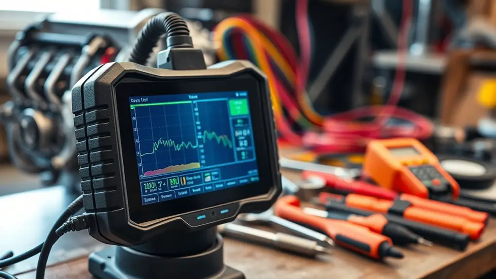
To prepare a manufacturer-level scan tool, start by verifying you have the exact tool model and firmware version required for your vehicle. You’ll confirm compatibility with the vehicle’s ECU protocol, then inspect the device for firmware integrity and recent updates. Next, consult the user manual to understand hardware ports, power requirements, and activation steps, guaranteeing you follow each specification precisely. Check all connectors for secure mating, shielding, and cleanliness to prevent communication errors. Verify battery or power supply stability to avoid mid-diagnostic resets. Establish a clean workspace, free of EMI sources, to maintain signal integrity. Review the tool features that align with your diagnostic goals, prioritizing data logging, real-time sensors, and fault-code interpretation. After setup, perform a basic self-test and record baseline readings. Maintain versioned notes for traceability, and ascertain the device is configured for your vehicle’s service procedures. This preparation promotes reliable, repeatable results and aligns with the user manual.
Safety and Vehicle Preparation

Before you start, verify the vehicle is in Park (or Neutral if required) with the parking brake engaged, and set the wheels straight to prevent unintended movement. Ascertain the area around the vehicle is clear of bystanders, and remove any loose clothing or jewelry that could snag on components. Confirm proper parking setup and required precautions are in place before you connect the tool or begin diagnostics.
Precautions Before Work
Before you begin, make certain the vehicle is in a well-ventilated, level area and the engine is off with the key removed. You’ll approach preparations with discipline, ensuring safety margins while you maintain control over the diagnostic environment. This phase minimizes risk and enhances reliability of readings from sensor calibration and diagnostic equipment.
1) Verify tool integrity and battery condition to prevent false readings during setup.
2) Disconnect unnecessary power drains and secure loose connections to avoid interference.
3) Confirm seat, hood, and pedals are free of obstructive items for smooth tool access and accurate data capture.
Proper Parking Setup
Proper parking setup requires deliberate placement and secure conditions before diagnostics. You verify the vehicle is on a flat surface, in park, with the parking brake engaged, and wheels straight to minimize shift during sensor checks. Chock rear tires if on an incline, and disconnect any heavy loads that could affect readings. Confirm ambient lighting and weather do not skew sensor inputs. Maintain a clean workspace to prevent debris ingress. Use proper vehicle positioning to standardize test conditions, then document each clearance and angle for repeatability. Table below illustrates key steps and outcomes for sensor calibration techniques.
| Step | Outcome |
|---|---|
| Positioning | Consistent baseline |
| Stabilization | Minimized motion |
| Environment check | Stable readings |
Connecting the Tool to the Vehicle Network
You’ll establish the vehicle network connection by locating the OBD port and confirming compatibility with the tool. Verify the link between the tool and the vehicle network using the correct protocol and termination method, then validate that the diagnostic session can initialize without errors. Ascertain secure, documented communication paths to prevent interference and maintain data integrity.
Vehicle Network Connection
To connect the tool to the vehicle network, start by identifying the appropriate data link connector and physical interface used by the vehicle, then secure a clean, vibration-free connection to guarantee stable communication.
- Confirm the vehicle’s network topology and supported protocols to align your tool’s session with the correct network protocols.
- Use proper grounding and shielding to minimize EMI, preserving signal integrity across the data link.
- Verify the tool’s baud rate, message timing, and diagnostic session level to ascertain reliable vehicle communication and data exchange.
This methodical approach reduces errors, accelerates fault tracing, and keeps you in control of accurate sensor readings while preserving system integrity and safety.
Tool-to-Vehicle Link
When connecting the tool to the vehicle network, start by confirming the data link connector type and the vehicle’s physical interface, then establish a clean, vibration-free connection to guarantee stable communication. You’ll verify tool compatibility before any data transfer, verifying the interface supports required protocols and baud rates. Maintain a steady link to minimize errors, monitor for signal consistency, and document any deviations immediately. A stable connection is the foundation for accurate sensor readings and reliable diagnostics.
| Step | Action | Outcome |
|---|---|---|
| 1 | Confirm DLP and interface | Tool compatibility confirmed |
| 2 | Attach tool, secure vehicle grounding | Connection stability assured |
| 3 | Initiate handshake, test data flow | Stable communication established |
| 4 | Begin diagnostics, log results | Predictable, repeatable measurements |
Selecting the Correct Modules and Destinations
Selecting the correct modules and destinations starts with understanding the scan tool’s architecture: each module corresponds to a vehicle subsystem, and each destination points to a specific ECU or data channel. You’ll map functions to hardware so you can isolate faults without guesswork, keeping your workflow efficient and deliberate. Prioritize accurate module selection to reduce cross-talk and misinterpretation of sensor data, then verify destination accuracy against OEM schemas before forcing queries.
1) Confirm module numbers align with vehicle documentation, then cross-check with live responses to ascertain the subsystem responds as expected.
2) Validate each destination path against the ECU layout, making certain the data channel corresponds to the intended parameter without masking anomalies.
3) Use a minimal set of targeted requests to avoid sensor lag or misleading readings, iterating only when results indicate an actual discrepancy.
Real-Time Data Logging Setup
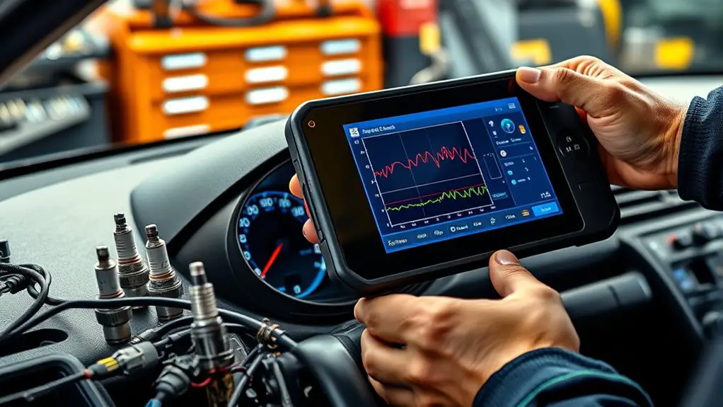
Real-time data logging begins with establishing a stable baseline and selecting the right channels to monitor. You’ll configure the tool for continuous capture, enabling timestamps and sample rates that reflect your system’s dynamics. Prioritize channels that directly affect sensor accuracy, and lock in a repeatable logging window to support real time analysis. Keep metadata concise: asset ID, test condition, and version.
| Channel | Sampling Rate | Purpose |
|---|---|---|
| Temp 1 | 50 Hz | Thermal drift baseline |
| Pressure | 20 Hz | Pressure response |
| Voltage | 100 Hz | Sensor power stability |
| Channel 1 | Channel 2 | Channel 3 |
| baseline | delta | stability |
After starting logging, verify data integrity with checksum and pause to confirm synchronized timestamps. Use these logs to compare against expected behavior, ensuring data accuracy and repeatability across runs. Real-time analysis benefits from clean, well-structured datasets and clearly defined logging parameters.
Interpreting Sensor Fault Codes and Alerts
Building on the real-time data you’ve been collecting, you’ll interpret fault codes and alerts by mapping codes to likely fault modes, checking sensor status against baseline expectations, and validating timestamps to rule out data skew. You’ll translate each fault code into a concrete description of probable causes, then corroborate with sensor health indicators and recent calibrations. Alerts should be categorized by severity and likelihood, enabling you to prioritize corrective steps without distraction. Precision in interpretation reduces false alarms and accelerates troubleshooting.
- fault code identification: map code families to specific sensor failures and corroborate with calibration logs.
- sensor calibration techniques: verify that recent recalibration matches OEM baselines and environmental conditions.
- alert validation: cross-check timestamps, data sampling rate, and paired sensor readings to confirm anomaly legitimacy.
Verifying Data Integrity and Cross-Checking With Live Graphs
To verify data integrity, you’ll cross-check live readings against expected ranges and recent baselines, then examine the correlation between adjacent sensors on the same system. You’ll run real-time graphs to visualize trends, noting spikes, plateaus, and drift that Falter the model’s truth. Approach data validation with a disciplined mindset: confirm that units, scaling, and offsets align across channels, and track timestamp consistency to avoid misalignment artifacts. Compare new samples to short-term baselines and to the last valid window; flag deviations beyond defined thresholds for immediate review. Assess sensor performance by evaluating response consistency under changing conditions, and note any hysteresis or lag that could distort interpretation. Use synchronized graphs to validate simultaneity of readings, ensuring that cross-sensor relationships reflect physics rather than tool quirks. Document anomalies with precise criteria, and reserve re-scans for confirmed outliers to prevent redundant verification.
Baseline Comparisons and Diagnostic Verification
Baseline comparisons are essential for distinguishing genuine changes from measurement noise; by anchoring current readings to short-term baselines and the most recent valid window, you can identify drift, offsets, and systemic shifts. Baseline analysis guides diagnostic verification by revealing where readings diverge from expected patterns, enabling targeted checks and faster root-cause isolation. You’ll confirm sensor calibration status, rule out transient perturbations, and quantify measurement stability over time.
- Establish short-term baselines from validated samples and current operating conditions.
- Compare to the most recent valid window to detect drift, offsets, or sensitivity changes.
- Use findings to guide calibration decisions and verify sensor integrity before proceeding.
This approach keeps you grounded in data, not assumption, making your toolset precise and repeatable. By pairing baseline analysis with disciplined sensor calibration checks, you reduce false positives and improve confidence in your diagnostic conclusions while maintaining operational freedom.
Documentation and Reporting of Findings
When you document findings, start from the baseline context established earlier and move into structured, auditable records. You’ll present observations with traceable timestamps, tool identifiers, and affected sensor channels. Use clear, non-ambiguous terminology and define any abbreviations on first use. Organize data into sections: executive summary, methods, results, conclusions, and recommendations, each referencing unique case identifiers. Emphasize reproducibility by attaching raw logs, snapshot diagrams, and calibration notes, then annotate any deviations from expected baselines.
Adhere to established reporting standards to maintain consistency across teams and audits. Apply documented methods that map measurements to specific sensor inputs, software versions, and vehicle configurations. Include tolerance thresholds, uncertainty ranges, and decision criteria used for pass/fail determinations, with explicit rationale. Maintain version control for the documentation Methods and Results, so updates remain auditable. Conclude with actionable next steps, residual risks, and required follow-up tests, keeping the record concise yet thorough for independent verification and future reference.
Frequently Asked Questions
How Often Should You Calibrate the Scan Tool’s Sensors?
You should calibrate the scan tool’s sensors at a defined interval, not ad hoc. Calibration frequency depends on usage, environment, and manufacturer guidance, but you should aim for routine checks every 6 months or after 1,000–2,000 cycles, whichever comes first. Maintain documented calibration logs to support sensor accuracy over time. If you notice drift, recalibrate immediately. This approach guarantees sensor accuracy and sustained tool reliability, balancing precision with operational freedom.
What if Data Formats Differ Between Modules and Tools?
When data formats differ between modules and tools, you mitigate issues with data translation and verify module compatibility first. You’ll map each field to a common schema, maintain endian conventions, and confirm timestamp integrity. If translation fails, you adjust parsing rules or update firmware to restore compatibility. Document the changes, test across scenarios, and guarantee your tool supports fallback modes. This disciplined approach keeps your system flexible while preserving accuracy and operational freedom.
Can You Reuse Stored Logs for Future Diagnoses?
Yes, you can reuse stored logs for future diagnoses. Stored log benefits include quick context recall, trend verification, and continuity across sessions, boosting diagnostic accuracy. As you reopen past data, you’ll compare baselines, spot deviations, and confirm patterns with precision. You’ll curate what’s relevant, ensuring you don’t chase noise. In this methodical approach, you preserve freedom to explore hypotheses, while maintaining disciplined, repeatable analyses that sharpen your overall diagnostic accuracy.
How Do You Verify Sensor Readings Without Vehicle Motion?
You verify sensor readings without vehicle motion by static testing and controlled inputs, confirming stability across cycles. You perform sensor testing with a calibrated tool, compare against known references, and log repeatable results to guarantee diagnostic accuracy. You isolate variables, monitor environmental effects, and document tolerances, then recheck consistency under simulated conditions. You assess noise, hysteresis, and offset, validating that readings stay within spec before drawing conclusions about sensor health and system integrity.
What Privacy Considerations Apply to Data Captured by Tools?
Data protection and user consent govern what you capture with tools. You should minimize data collection to what’s strictly necessary, disable unnecessary telemetry, and anonymize or pseudonymize sensitive details. You’re responsible for obtaining explicit user consent before storing or sharing readings, and you must document data handling practices. Establish clear retention limits, secure transmission, and access controls. Regularly review permissions, notify users of changes, and provide opt-out options to uphold privacy while you pursue accurate diagnostics.