Step-By-Step: Using a Manufacturer-Level Scan Tool to Diagnose OBD Adapter Connection Failure
To diagnose an OBD adapter connection failure, start by confirming tool compatibility and vehicle coverage, mapping your make, model year, and trim to the tool’s supported list. Set up the physical link with clean cables, secure adapters, correct pin alignment, and proper ignition on. Establish baseline communication, then verify protocol handshakes and data-link integrity, logging any errors. Isolate cables, power, or ECU issues, and document findings with clear next steps for repeatable diagnostics. If you keep going, you’ll uncover deeper troubleshooting steps.
Verifying Tool Compatibility and Vehicle Coverage
Verifying tool compatibility and vehicle coverage is the first step to a reliable scan. You’ll confirm that the scan tool’s capabilities match your investigation needs, not just its core functions. Start with tool specifications: supported protocols, data transfer speeds, and memory limits matter when you’re chasing a stubborn connection issue. Next, map your vehicle models to the tool’s coverage list, ensuring the adapter and software recognize the exact make, model year, and trim. Don’t overlook region-specific variants or updates that can affect OBD behavior. Check license tiers or subscription requirements that enable advanced diagnostics for particular models. Validate that the tool supports the required diagnostic modes and service procedures without forcing workarounds. If you’re proceeding with multiple vehicles, document coverage per model to prevent misalignment later. This approach keeps your path clear, minimizes surprises, and preserves your freedom to diagnose confidently. Tool specifications and vehicle models guide the initial verification.
Setting Up the Connection: Cables, Power, and Connectors
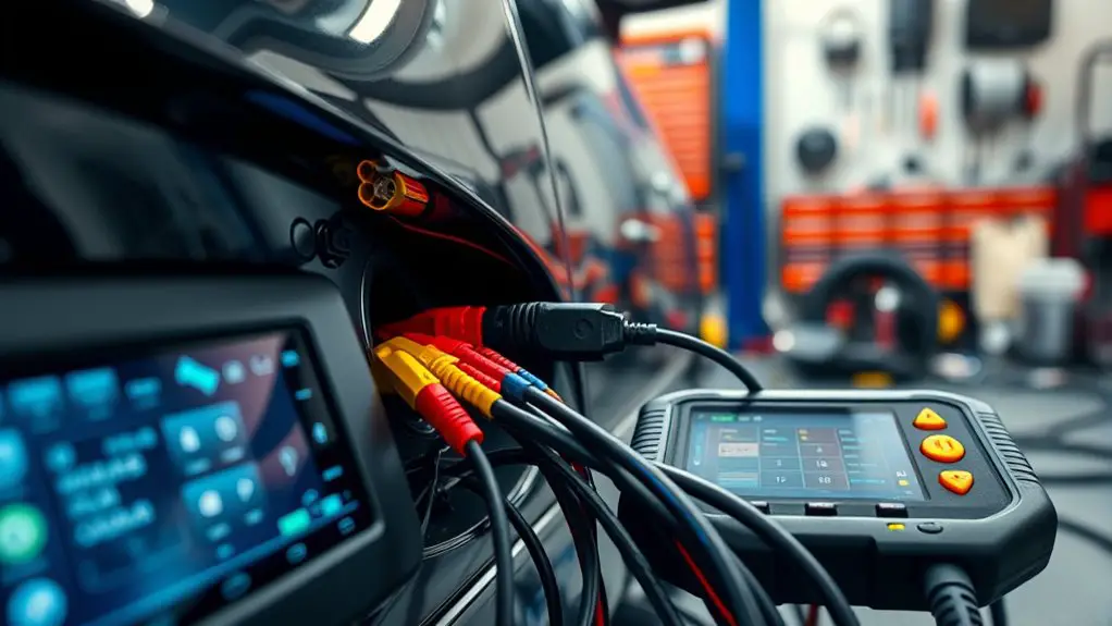
You’ll start by confirming the power source and cable integrity before connecting the scan tool. Inspect the cables, connectors, and adapters for any wear, then verify proper pin alignment and secure fittings. With power supplied and connections seated, proceed to test the link and verify data flow through the OBD interface.
Power and Cables
To set up the connection, start with the vehicle’s power source and the right cables: make certain the ignition is on or in accessory mode as required by your OBD adapter, and choose a compatible OBD-II cable that matches both the adapter and the vehicle. You’ll confirm a solid power supply by testing battery voltage and ensuring the fuse path for the OBD port is intact. Inspect cable types for quality and shielding, avoiding damaged insulation or loose connectors. Route cables away from heat, moving parts, and sharp edges to prevent wear. Use a manufacturer-approved power adapter if the tool demands it, and keep a clean, organized area to minimize interference. Once power and cables are verified, proceed to stable data communication and diagnostics.
Connector Setup
With power and cables in place, you’re ready to set up the connectors that establish the data link. You’ll verify connector types and align them to the tool’s input ports, guaranteeing the physical interface matches the required standard. Check pin configurations for critical signals (power, ground, data lines) and note any nonstandard spacing or keyed features that prevent misconnection. Secure the connector firmly to avoid intermittent contact, then inspect for bent pins or debris before power is applied. Confirm the accessory’s protective caps are removed only when connected, and store them to avoid loss. Finally, test a light tug on the harness to verify retention and prepare for a clean diagnostic session.
- Guarantee connector types match the tool and vehicle interface
- Confirm pin configurations align with the diagnostic protocol
- Secure and inspect all connections prior to power-on
Establishing Baseline Communication With the Vehicle
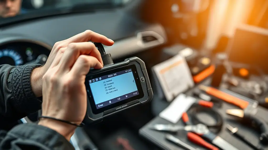
Establishing baseline communication with the vehicle starts by verifying the scan tool’s connection to the OBD interface and confirming the ECU’s responsiveness. You’ll perform a minimal handshake to guarantee the tool recognizes the vehicle network and that no physical faults block access. Next, initiate a baseline diagnostic session and request essential identifiers, such as the ECU type, protocol, and supported services. If the tool reports vehicle readiness, you’re closer to stable communication. Record initial status flags and any error codes, but avoid jumping to conclusions—baseline communication is about establishing a clean starting point. Confirm that the ignition is in the correct position and that no aftermarket adapters or adapters’ resistors are interfering. If the ECU responds with a positive status and stable data flow, you’ve achieved a reliable baseline. From here, proceed to targeted queries, keeping your focus on consistent data, reproducibility, and future diagnostic repeatability. Maintain discipline to avoid unnecessary chatter that could obscure vehicle readiness.
Checking Protocols and Data Link Layer Integrity
If you detect shaky timing or mismatches in responses, start by validating the protocol level handshakes and ensuring the data link layer is correctly synchronized. You’re checking that the transport and physical layers aren’t dropping frames or misaligning timestamps, because protocol integrity relies on clean exchanges. Perform zero-latency checks where possible, and confirm that each sent request receives a matching, timely response. Use data validation to verify CRCs, checksums, and length fields before interpreting payloads. If discrepancies appear, pause automated retries and document the exact conditions, then re-sync at the link layer before resuming higher-layer tests. This disciplined approach prevents cascading errors and preserves diagnostic accuracy under real-world conditions. Maintain a record of states, timeouts, and error codes to guide future comparisons and tooling improvements.
- Validate handshakes and synchronize data link timing
- Verify CRCs, checksums, and length fields for data validation
- Log timing, errors, and state changes for protocol integrity analysis
Isolating Cable, Power, or ECU Responsiveness Issues
To isolate cable, power, or ECU responsiveness issues, begin by swapping suspect cables and connectors one at a time to identify any intermittent or visible faults, such as loose pins or damaged insulation. You’ll want to trace each path from the scanner to the OBD adapter, testing continuity with a multimeter where practical and inspecting for corrosion or pin bend. Prioritize cable testing on the data lines first, then verify shield integrity and connector latches. If symptoms persist, swap the power supply or supply cable next, ensuring the unit receives a steady, within-spec voltage and current limit. Confirm ground integrity at the OBD port and scanner chassis; a marginal ground can masquerade as ECU non-responsiveness. Document changes and outcomes to build a diagnosis trail. If the tool relies on a separate power source, temporarily run off a known-good supply to rule out timing or voltage-related faults. This methodical approach reduces guesswork and accelerates isolation of the root cause.
Safe Troubleshooting Techniques to Avoid Damage
To minimize risk, start with Safe Handling Practices by disconnecting power before connecting or removing any OBD adapter. Follow Preventive Diagnostic Steps to verify tool compatibility and inspect cables for wear, ensuring proper grounding and secure connections. Maintain a methodical workflow, document each step, and halt if you encounter unexpected resistance or signs of damage.
Safe Handling Practices
Safe handling starts with small, deliberate steps to prevent damage to the vehicle, the OBD adapter, and the scan tool. You keep contact clean, avoid forcing connectors, and verify compatibility before insertion. Use proper handling techniques to minimize static risk, inspect cables for wear, and detach power when not testing. Maintain organized workspace and designate a dedicated storage area to prevent misplaced parts. Safe equipment storage is essential for longevity and reliability.
- Keep connectors capped when not in use and store in anti-static bags
- Handle cables by connectors, not by cable bodies, to reduce strain
- Label and segregate tools and adapters to prevent cross-contamination and misuse
Preventive Diagnostic Steps
Preventive Diagnostic Steps: start with a structured checklist to minimize risk before any probing or port insertion. You’ll verify tool compatibility, confirm vehicle and tool firmware versions, and inspect connectors for corrosion or debris. Next, power down the vehicle and the diagnostic tool, then unplug all cables to prevent accidental shorts. Ground yourself, then recheck the environment for static risks. When you reassemble, use recommended dwell times and gentle seating to avoid pin misalignment. Use diagnostic tools in a modular, non-invasive sequence: begin with basic communication tests, then proceed to protocol negotiation, keeping sessions brief to reduce wear. Document each step, note anomalies, and halt if readings deviate outside spec. This approach supports preventive maintenance and preserves tool longevity while maintaining performance freedom.
Recording Findings and Next Steps for Reproducible Diagnostics
When documenting findings, start with a clear, objective summary of the failure mode, the exact tools and firmware versions used, and the observed symptoms. You’ll record the sequence of events, note any deviations, and attach timestamped logs. Focus on reproducibility: include test conditions, wiring diagrams, and calibration state. For later review, generate concise diagnostic reports that translate findings into actionable steps. Preserve chain of custody for data, configurations, and tool screenshots. Emphasize traceability, so others can reproduce the scenario or challenge results.
- Clearly state the failure mode, toolset, firmware, and exact symptoms with timestamps
- Attach verifiable logs, screenshots, and re-test results to support conclusions
- Define next steps, acceptance criteria, and rollback or fallback procedures
Use precise terms, avoid fluff, and guarantee the record keeps moving toward a reproducible conclusion through disciplined record keeping and diagnostic reports.
Frequently Asked Questions
How Do You Verify Tool Firmware Compatibility With the Vehicle’s ECU?
Firmware fits if firmware updates match ECU specifications exactly. You verify by cross-checking the tool’s firmware release notes against the vehicle’s ECU protocol, chipset, and software version, then run a compatibility check in the tool’s module manager. Make certain you’re aligned with OEM documentation, confirm checksum or cryptographic signature, and test a noncritical drive cycle. If discrepancies appear, don’t proceed; update firmware or revert to the approved version before proceeding.
Can Adapter LEDS Indicate Specific Fault Types Beyond Basic Status?
Yes, adapter LEDs can help, but they rarely encode highly specific fault types. You’ll typically see LED indicator meanings tied to basic statuses (power, link, activity) rather than granular faults. For fault type identification, rely on the tool’s diagnostic codes and live data. Use LEDs as quick sanity checks, then drill into the ECU data stream to confirm or refine fault categories. Maintain a methodical flow and document results for reproducibility.
What Error Codes Indicate a Non-Ecu-Related Connection Issue?
Only a few non-ECU issues trigger clear error codes; look for connection diagnostics like CAN bus timeouts or no-communication faults. These aren’t ECU faults, but indicate wiring, adapter, or baud-rate problems. In error interpretation terms, codes such as UBs or P0? references can appear when the tool can’t establish a stable link. About 60% of failed sessions stem from physical connections, so verify pins, ground, and shield first.
Are There Hidden Handshake Steps Required by Certain OEM Tools?
Yes, some OEM tools require hidden handshake steps. You’ll need to align with handshake protocols and OEM specifications, otherwise sessions fail. Start by confirming device firmware, security keys, and nonces, then follow the secure-transport sequence precisely. You should authenticate before data exchange, respect baud rate and timing, and honor channel encryption expectations. If a step seems undocumented, assume an additional challenge or rekey, and verify compatibility with the tool’s vendor.
How to Distinguish Between Tool Timeout and ECU Response Delay?
You can distinguish them by observing timing patterns: timeout causes are abrupt, complete failures when the tool stops waiting, while ECU response delays show gradual latency or partial responses. Measure round-trip times, compare against baseline, and log successive polls. If retries fail consistently with the same cutoff, it’s a timeout; if you see sporadic late replies, it’s a response delay. Correlate with bus load, priority, and diagnostic service type for accurate separation.