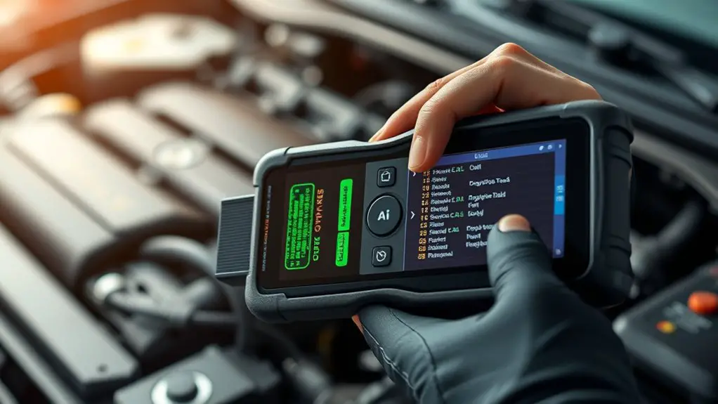
Step-By-Step: Using a Manufacturer-Level Scan Tool to Diagnose Can’t Read OBD Codes
Power the tool and confirm it’s recognized by the diagnostic computer, then calibrate it to your vehicle’s make, model, and year. Verify tool compatibility with your model and guarantee the right protocol and data speed. Access the diagnostic menu, select the correct subsystem, and establish a handshake before data calls. Read manufacturer codes, map OEM codes to meanings, and monitor live data for anomalies. Clear codes only after root causes are resolved, or you’ll miss critical clues—more steps await.
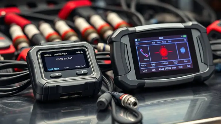
Tool Verification and Setup
To begin, verify that your manufacturer-level scan tool is properly powered and recognized by the diagnostic computer. Next, connect the tool to the vehicle’s data link port and confirm the ignition is in the on position without starting the engine. Confirm communication by observing the handshake indicators on the tool’s display and the diagnostic software. If recognition fails, cycle power, re-seat connectors, and reinitialize the USB/ETHERNET/WIFI channel as applicable. Proceed to tool calibration by following the procedure outlined in your user manual, selecting the correct vehicle make, model, and year. Establish a baseline by performing an empty run to confirm system stability and eliminate false positives. Verify date, time, and software revision to confirm compatibility with current diagnostic procedures. Document the calibration state and any fault flags. Maintain a clear record for future reference, and store credentials and licenses securely for authorized use. This straightforward setup supports precise, repeatable diagnostics.
Vehicle Compatibility Check
You’ll start by confirming the tool’s compatibility with both the vehicle’s make and model, as well as the year range and system family you’ll access. Next, reference the Tool Compatibility Guide to verify supported protocols, connector types, and software versions before you connect. This guarantees you can accurately retrieve OBD codes and perform meaningful diagnostics without compatibility gaps.
Vehicle Compatibility Check
A vehicle compatibility check guarantees the scan tool and the vehicle’s data protocols can communicate correctly before diagnostics begin. You verify that the tool supports the car’s protocol, data speed, and supported service IDs, confirming a stable link for subsequent steps. You compare the tool’s listing of supported vehicles to the exact year, make, model, and engine code, aligning each parameter to avoid mismatches. You assess the data bus type, wake-up method, and security access requirements, ensuring you won’t encounter unexpected prompts during fault reading. You document applicable vehicle specifications and any noted system limitations that could affect live data or freeze-frame reads. You reserve judgment on results until you confirm bidirectional communication, readouts, and stability across representative operating conditions.
Tool Compatibility Guide
Tool compatibility hinges on confirming the vehicle’s data protocol and the scan tool’s capabilities match precisely before diagnostics begin. You’ll verify protocol support, feature scope, and firmware compatibility to prevent misreads or tool lockouts. Focus on how tool features align with your test plan, and assess the user interface for efficiency under pressure. A compatible setup reduces uncertainty and speeds fault isolation, letting you trust live data and freeze-frame records during steps.
- Confirm vehicle data protocol, supported PIDs, and supported modes
- Assess tool features for bi-directional control, per-ISO standards, and update cadence
- Evaluate the user interface for clear data presentation, quick access, and reliable error messaging
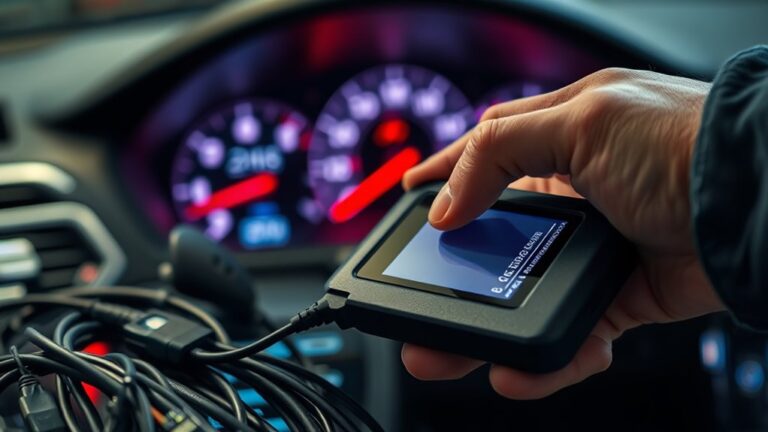
Accessing Diagnostic Modes
Accessing diagnostic modes is the first step in effectively using a manufacturer-level scan tool. You begin by powering down, then connect to the vehicle’s data-link port with the tool secured. Ascertain the tool recognizes the vehicle model and year before progressing. Enter the main menu and locate the diagnostic section, not the dealership-style splash screens. Select the most appropriate subsystem based on your symptoms, then switch to the specific diagnostic mode that corresponds to the task at hand. You’ll typically access modes for read/clear codes, real-time data, and component tests; map your goal to the correct mode precisely. Maintain a steady, methodical rhythm as you navigate prompts, avoid abrupt selections, and confirm each step before proceeding. Document results as you go, noting any deviations from expected prompts. Remember, accessing modes is foundational; clean, accurate setup simplifies every subsequent diagnostic step and supports reliable results.
Confirming Communication Protocols
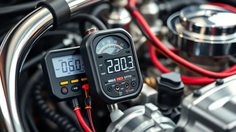
Once you’ve established the correct diagnostic modes, you must verify the tool and vehicle communicate reliably before proceeding with any tests. Confirming communication protocols is about matching the tool’s interface to the vehicle’s data layer. You’ll check that the tool negotiates the expected baud rate, voltage levels, and timing, and that the session begins without errors. Be aware of communication standards and protocol variations across manufacturers, as firmware updates or model changes can shift expectations. If the tool reports a mismatch, restore compatibility by selecting the correct protocol profile or updating the tool’s cross-check databases. Do not assume one standard fits all; validate each channel and message handshake before subtests.
- Verify the active protocol and session initialization before any data call
- Confirm voltage, timing, and baud parameters align with the vehicle’s expectations
- Document any protocol variations observed for traceability and future tests
This disciplined verification keeps subsequent diagnostics precise and reliable.
Reading Manufacturer Codes
Reading Manufacturer Codes requires isolating manufacturer-specific fault indicators from generic codes, then interpreting them within the vehicle’s data layer. You’ll map each dealer- or OEM-originated code to its precise meaning, distinguishing it from standard OBD-II identifiers. Begin by locating the exact fault category in the tool’s manufacturer code definitions, noting any prefixes, suffixes, or numeric ranges that signal subsystem context. Next, correlate the codes with stored service procedures, bulletin references, or calibration IDs to confirm applicability to your vehicle model. As you interpret manufacturer codes, maintain a disciplined approach: document code strings, time stamps, and test conditions to support diagnosis and potential repairs. Maintain consistency with the data hierarchy, ensuring you’re not conflating generic faults with manufacturer-specific indicators. This practice yields clearer fault trees, actionable steps, and reduces unnecessary part swapping. Remember, interpreting manufacturer codes elevates diagnostic precision and empowers measured, targeted fixes.
Live Data vs. Freeze Frame
Live data and freeze frame are complementary diagnostic tools: live data streams real-time sensor values and control states, while freeze frame captures a snapshot of these values at the exact moment a fault code is stored. You’ll use them together to build context: live data shows current conditions, freeze frame records the conditions tied to the fault. This pairing helps you identify intermittent issues and verify system integrity without guessing.
Live data shows current conditions while freeze frame fixes the fault moment for reproducible insight.
- live data benefits: observe trends, correlations, and timing between signals
- freeze frame importance: anchors fault conditions to a specific moment for reproducibility
- practical workflow: compare current readings to stored snapshot to confirm abnormality
Verifying Fault Codes With Real-Time Sensors
To verify fault codes using real-time sensors, start by cross-checking the stored codes against current sensor readings and control states. You’ll compare sensor data interpretation with the implicated parameters, ensuring the real-time values align with the diagnostic expectations for each fault. Focus on correlations between engine, transmission, and emission sensors and the corresponding fault codes to confirm consistency rather than coincidence. Document any discrepancies between fault code correlation and live data, noting where readings deviate from normal ranges or where sensor interpolation may mask a fault. Use the scan tool to monitor parameter trees in synchronized time windows, then isolate which sensor trends most closely reflect the coded issue. Maintain a disciplined approach: verify both persistence and reproducibility of the readings, and reassess after minor load or rpm changes. This method clarifies reality versus artifact, enabling confident diagnostic steps and precise next actions.
Clearing Codes Safely
Clearing codes safely requires a disciplined, stepwise approach to guarantee faults aren’t hidden or misrepresented by transient conditions. You’ll validate the need to erase codes only after confirming that the root causes are resolved or isolated. Use the tool’s clear command with the proper mode, then observe whether MIL illumination behaves consistently. Confirm pending codes are cleared, and recheck with a fresh read after a short drive to ascertain no new faults emerge.
Proceed cautiously: clear codes only after resolving root causes, verify no lingering conditions, then recheck with a fresh read after a short drive.
- code clearing techniques: verify fault resolution before erasing, and ascertain no dynamic conditions linger
- safe disconnection methods: power down procedures and connector handling to avoid data corruption
- verification after clearance: reinitialize sensors, run a diagnostic cycle, and confirm no pending codes return
Proceed with caution: document each step, including all vehicle conditions and tool responses. Maintain a deliberate pace, focusing on reliability over speed, so you preserve the integrity of the diagnostic trail and support future maintenance decisions.
Common Pitfalls and Workarounds
When you diagnose with a manufacturer-level tool, you’ll encounter Pinpoint Diagnostic Traps that can mislead if you overlook data context. You’ll also navigate Bypass Coding Gaps by recognizing where standard routines skip or mask fault details, requiring cross-checks with protocol-specific logs. Finally, Tool Protocol Nuances demand attention to vendor-specific command sets and session states to prevent misinterpretation of results.
Pinpoint Diagnostic Traps
Pinpointing diagnostic traps requires a disciplined approach: start by verifying the scope of the fault, then distinguish between connector, wiring, sensor, and ECU issues before chasing a code. You’ll apply diagnostic strategies that separate symptom from root cause, preventing misdirection into irrelevant subsystems. Treat each potential fault area as an independent module, validating inputs, references, and grounds before proceeding. Maintain a concise log of observations, test results, and timestamped changes to avoid repeating steps. When a code is misleading, revalidate with supplementary data—scan tool live data, measured values, and DTC freeze frame. Stay disciplined, and don’t chase a code you can’t substantiate with confirmable evidence. This mindset sharpens troubleshooting techniques and enhances repair confidence.
- Verify scope before chasing codes
- Separate modules to prevent cross-talk
- Document results for traceable diagnostics
Bypass Coding Gaps
Bypass coding gaps often trips up diagnosis when the tool’s output doesn’t align with actual vehicle behavior; the key is to identify where the scan tool’s data diverges from real-world signals and then apply targeted workarounds. You’ll evaluate mismatch points by cross-checking live sensor streams, GRPs, and actuator responses, then select a bypass technique that preserves data integrity. Focus on aligning stored codes with current diagnostics, rather than forcing a single reading to fit. Employ disciplined, repeatable steps: confirm codes, reproduce fault, monitor equivalents, and document behavior shifts. Implement coding strategies that neutralize nonessential flags while preserving essential safety and emission data. Use bypass techniques for root-cause clarity, not to mask underlying faults; aim for accurate, actionable results.
Tool Protocol Nuances
Tool protocol nuances hinge on how data flows from the scan tool to the vehicle ECUs. You’ll encounter protocol differences that affect data availability, timing, and interpretation. Understanding these distinctions helps you identify where your tool’s access or speed limits become bottlenecks, and guides you toward effective workarounds. Stay precise about the tool’s capabilities, and document any deviations you observe between expected and actual responses. Be mindful of sensor update rates, message IDs, and broadcast vs. targeted requests, since these factors shape diagnostic outcomes. Recognize tool limitations early to avoid false negatives and wasted time. With disciplined protocol awareness, you preserve momentum while maintaining accuracy.
- Choose protocols aligned with vehicle generation and ECU type
- Test sequentially to isolate where data gaps occur
- Record deviations for vendor support and future reference
When to Escalate to Advanced Diagnostics
When you’re using a manufacturer-level scan tool, escalate to advanced diagnostics when the basic scans fail to identify a clear fault, or when symptoms persist despite corrected codes. You’ll shift from filter-based checks to targeted data analysis, focusing on persistent patterns rather than single-event alarms. Begin by reviewing current escalation criteria: verify misfires, abnormal sensor trends, and drivability complaints that lack diagnostic trouble codes. If you observe inconsistent injector pulse widths, irregular MAP/MAF correlations, or suspect electrical grounding issues, initiate advanced techniques such as deep data logging, waveform capture, and module-to-module communication tests. Cross-check with alternate diagnostics from the OEM, and compare live data against manufacturer service bulletins. Document every anomaly, including timing, scope, and affected systems. Escalation isn’t a guess; it’s a structured path toward isolating root causes when standard scans don’t converge. Maintain rigor, repeatability, and traceability throughout the diagnostic process.
Frequently Asked Questions
Can Tool Firmware Updates Fix Unreadable OBD Codes?
Yes, tool firmware updates can help, but they’re not a cure-all. If codes are unreadable, firmware improvements may enhance communication stability and reduce false negatives, improving diagnostic accuracy. You’ll want to verify the update path, release notes, and supported adapters for your specific vehicle. Remember, updates address software glitches, not overt mechanical faults. Combine updated firmware with proper data interpretation, and you’ll preserve diagnostic accuracy while maintaining a sense of freedom in troubleshooting.
Do OEM Tools Require Vehicle-Specific Licenses?
License requirements vary by OEM and tool; some OEM tools require vehicle-specific licenses while others operate with broad access. You’ll encounter tool compatibility issues if licenses don’t match the supported vehicle makes or eras. In many cases, OEM tool licensing is mandatory for full functionality, updates, and factory codes. You’ll want to verify license scope, cross-check compatibility, and anticipate renewal needs to avoid gaps in diagnostic capability.
How Do You Verify a Tool’s CAN vs. K-Line Support?
You verify a tool’s CAN vs. K-line support by checking its documented data protocols and performing a live interface test. Look for explicit CAN, KWP2000, or K-line flags in the tool’s specs, then run a stall-free diagnostic session to confirm compatibility. Use diagnostic protocols like CAN-High/Low, ISO 9141-2, or ISO 14230. This guarantees tool compatibility, reliable data flow, and adherence to your vehicle’s protocols.
Can External Adapters Cause False Negatives in Readings?
Adapters can cause false negatives if they’re low quality, but high-quality adapter quality minimizes this risk. You should verify compatibility and shield against signal interference, especially in noisy environments. Yes, external adapters can introduce reading errors, so test with a known-good setup first. Confirm your adapter supports the protocol you’re testing, and check for impedance and shielding issues. By controlling adapter quality and reducing signal interference, you preserve reliable readings and maintain freedom in diagnostics.
What Safety Steps Prevent Data Corruption During Tests?
Yes. You protect data integrity by validating the test environment before you begin, using clean power, isolated grounding, and shielded cables. You’ll disable nonessential devices, preserve a stable clock, and log all changes. You maintain a tamper-evident setup, run integrity checks on storage, and verify tool firmware compatibility. You document every step, monitor for anomalies, and pause if corruption risk appears, then restart with fresh baselines to guarantee ongoing data integrity.