
Top 10 Diagnostic Tools Every DIYER Needs and How to Use Them
You’ll want a concise set of tools to diagnose and verify every system. Start with a digital multimeter for voltage, current, and resistance, then an OBD-II scanner for vehicle codes. Add a torque wrench, compression tester, and vacuum gauge for mechanical health. Use an infrared thermometer for hotspots, an oscilloscope or logic analyzer for signals, and proper probing gear for safe testing. Always document results and follow safety basics; more practical tips await if you keep exploring.
Digital Multimeter Essentials: Readouts, Modes, and How to Test
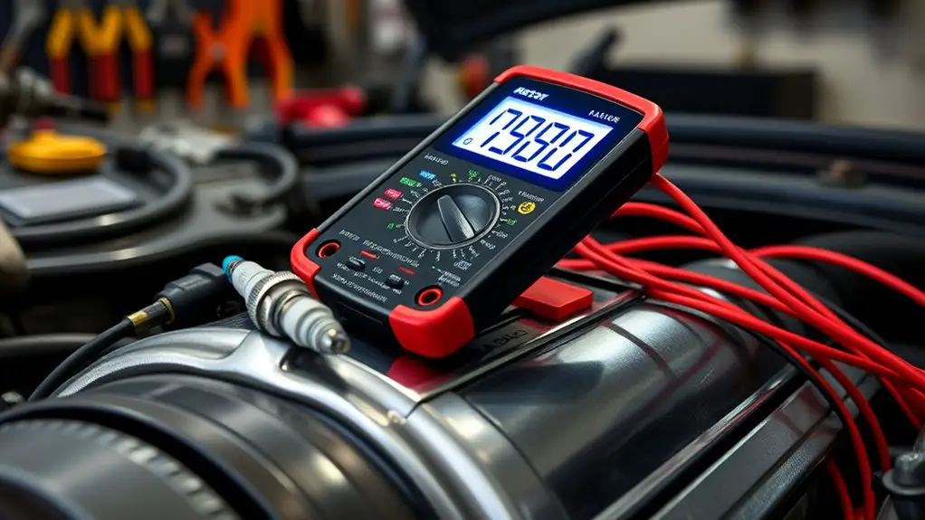
Digital multimeters, or DMMs, are purpose-built for measuring electrical parameters with a single instrument, so you can quickly verify voltage, current, and resistance without guessing. You’ll appreciate how readouts present values clearly, with units and sometimes a bar graph for trend. Learn to distinguish DC from AC by the mode selector; it matters for accuracy and safety. Multimeter features like auto-range, continuity beeps, and diode testing speed up decisions and reduce misreads. In testing procedures, set the appropriate range, connect probes with steady contact, and observe for spikes or drift. Keep the test leads in good condition, and use the common (COM) and measurement ports correctly to avoid damage. Document readings methodically, noting tolerances and environmental factors. Your goal is reliable data, not ambiguity, so verify with repeat measurements. With disciplined technique, you’ll trust your results and tackle more complex diagnostics.
Infrared Thermometer Use: Noncontact Temperature Tactics

Infrared thermometer use lets you capture noncontact temperature reads quickly and safely, concentrating on surface conditions without touching the target. You’ll assess hotspots and compare readings across components to identify abnormal temps that signal potential failures. Start with known-good baselines, verify distances, and document any deviations for hotspot troubleshooting.
Noncontact Temp Reads
Noncontact temperature readings with an infrared thermometer provide quick, noninvasive evidence of surface temperature. You’ll evaluate surfaces without contact, enabling rapid scans of equipment, wiring, and enclosures. Focus on accuracy: calibrate against known references, account for emissivity, and hold the device steady at the recommended distance. For noncontact applications, select appropriate settings for material type and reflectivity, and interpret readings within tolerances for your project. Use temperature measurement data to guide decisions about cooling, insulation, or component stress, but confirm suspicious results with a contact method if needed. Document conditions—ambient temperature, surface orientation, and angle—to guarantee repeatability. Maintain safety, protect sensors from moisture, and store units properly. This disciplined approach keeps your toolkit efficient without sacrificing independence.
Hotspot Troubleshooting
What signals a hotspot, and how can you verify it quickly with an infrared thermometer? You’ll use hotspot detection to pinpoint nonuniform heating and potential failures. Follow these steps with precision and intent:
- Identify abnormal temperature zones on equipment surfaces during operation.
- Compare readings against baseline specs to confirm deviations.
- Recheck with multiple angles to rule out reflective interference.
- Document trends to guide troubleshooting techniques and preventive actions.
This methodical approach minimizes guesswork and supports safe repairs. Use consistent distance, surface emissivity settings, and steady sweeps for reproducible results. Your freedom to fix things hinges on disciplined measurement. By integrating infrared thermometry into your diagnostic routine, you sharpen hotspot detection, streamline troubleshooting techniques, and reduce downtime without sacrificing safety. Stay curious, stay precise, and let data drive your decisions.
Code Readers and Scan Tools: Interpreting Vehicle Diagnostics
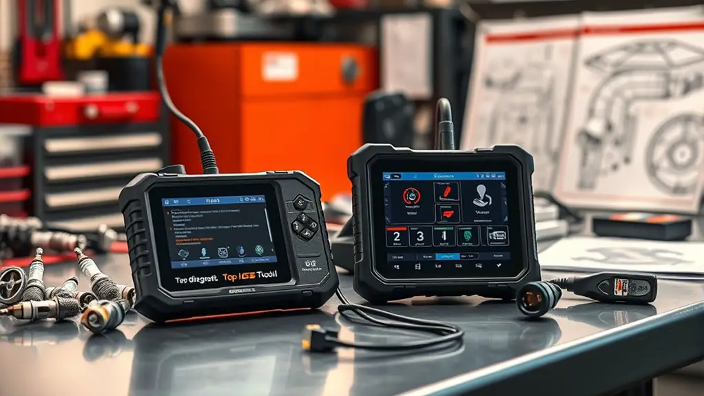
Code readers and scan tools are your first line of defense for diagnosing modern vehicles. You’ll approach diagnostics with a clear, structured mindset, focusing on data reliability and actionable insights. Begin with code reader basics: identify stored codes, pending codes, and freeze-frame data to anchor your investigation. Interpret the meaning of P-codes versus manufacturer-specific codes, then translate them into probable causes without jumping to conclusions. Next, evaluate scan tool features: live data streaming, graphing trends, and parameter thresholds that reveal intermittent issues. Use filters to isolate faults, compare current readings to baseline values, and note any deviations that align with your symptoms. Maintain a methodical workflow—verify codes, observe live data, reproduce symptoms, and rule out sensors before replacing components. Remember safety and documentation: record findings, clear codes only after repair, and recheck to confirm resolution. You’ll exploit these tools with disciplined curiosity and a sense of freedom.
Wire and Circuit Probing: Testers, Clamps, and Safe Handling
When you probe wires and circuits, start with safe techniques that prioritize control and visibility, such as confirming test paths before contact and using properly rated instruments. Maintain clean probe tips, secure clamps, and minimal contact time to reduce heat and noise pickup, and always verify instrument calibration and compatibility with the circuit under test. In practice, keep clearly labeled PPE and follow a repeatable sequence to minimize mistakes and protect both you and the equipment.
Safe Probe Techniques
Safe probe techniques are essential for accurate measurements and personal safety when working with wire and circuits. You’ll optimize readings by adhering to controlled probe handling and disciplined electrical safety.
- Inspect probes for cracks or frayed leads before every use, replacing worn parts immediately.
- Ground yourself and keep work surfaces dry to minimize shock risk during testing.
- Use insulated handles, clip leads lengthwise, and avoid contact with metallic parts while energized.
- Plan measurements, verify with a known reference, and document results for repeatability.
These steps empower you to probe confidently, balancing speed with precision. With disciplined probe handling, you preserve tool longevity and reduce danger, maintaining freedom to explore circuits safely.
Instrument Care Tips
Instrument care is essential for reliable readings and safe handling when probing with testers, clamps, and related accessories. You’ll maximize accuracy by inspecting probes for wear, loose connections, and insulation flaws before each use. Practice disciplined wire management to prevent accidental shorts and signal interference. Keep calibration dates current and log results to track drift over time. When handling live circuits, use appropriate personal protective measures and limit exposure to energized nodes. After sessions, wipe connectors clean and dry, and coil cables neatly to avoid kinking. Store tools in labeled bins to simplify retrieval and reduce cross-contamination between measurement types. Instrument maintenance and tool storage habits together extend lifespan, improve data quality, and support confident, freedom‑driven experimentation. Avoid clutter, perform routine checks, and replace worn components promptly.
Electrical Measurement Tools: Voltage, Current, and Resistance Basics
Electrical measurement is the backbone of safe, effective DIY electrical work, and understanding voltage, current, and resistance is essential to diagnose circuits accurately. You’ll use basic concepts to verify circuits and isolate faults without guesswork.
- Voltage measurement techniques: you measure potential differences with the proper range, probe placement, and reference to ground, ensuring no arc and using a calibrated meter.
- Current measurement methods: you employ in-line meters or clamp meters, maintaining conductor integrity and avoiding overloading the probe.
- Resistance basics: you test continuity and insulation by powering down, selecting the correct range, and interpreting open, short, or degraded paths.
- Safety and procedure: you de-energize circuits, discharge capacitors, and document readings to track changes over time.
Mastery combines accuracy, consistency, and a calm, methodical approach to diagnose faults quickly and safely.
Signal Probes and Logic Analyzers: Capturing Waves and Pulses
Signal probes and logic analyzers are essential tools for accurately capturing waves and pulses in real time. You’ll use probes to isolate signals at precise test points, while a logic analyzer records multi‑channel activity, revealing timing relationships that aren’t obvious on a single scope. Approach this methodically: verify ground references, choose appropriate bandwidth, and set vertical and timebase ranges to prevent aliasing or clipping. When capturing, label channels clearly and synchronize triggers to the event you’re studying, so you can reconstruct the sequence of logic states. Practice disciplined sampling: capture sufficient samples to support reliable signal waveform analysis, then review changes, duty cycles, and glitches with a critical eye. For modulation tasks, inspect pulse width modulation schemes at both fundamental and harmonic levels, confirming that PWM timing aligns with intended control signals. Use your findings to refine circuits, troubleshoot faults, and validate performance against design specifications.
Battery and Power Testing: Health Checks and Safe Disconnection
When evaluating battery health and power integrity, start with a clear checklist: verify the correct system ground, confirm safety precautions are in place, and inspect physical condition and labeling before any test.
You’ll approach this with discipline, tracking data points and outcomes to support confidence in battery maintenance and power analysis.
1) Safety-first disconnection: isolate the source, then secure cables with insulated grips and clear labels.
2) Baseline measurements: record voltage, current, and impedance, noting deviations from spec for trend analysis.
3) Load testing: apply controlled load steps, observe response times, and verify recovery without overheating.
4) Documentation and cycle care: log test results, maintenance dates, and upcoming service intervals to sustain reliability.
This methodical workflow minimizes risk while maximizing insight, keeping you in control. You’ll gain a sharper sense of power integrity, supporting confident DIY decisions and safer disconnections.
Oscilloscopes for DIYers: Visualizing Signals and Troubleshooting
You’ll start with solid probe techniques to capture clean, representative signals without loading the circuit. Look at signal waveforms to identify timing, amplitude, and noise issues, then apply targeted troubleshooting steps. This sets a precise foundation for diagnosing behavior across common DIY projects.
Probe Techniques
Probe techniques are about safely and accurately capturing waveforms with an oscilloscope, so you can diagnose timing, amplitude, and shape anomalies.
1) Understand probe types: attenuators, passive vs active, bandwidth limits, and ground leads.
2) Optimize probe placement: minimize loop area, shorten ground leads, and align to the source impedance.
3) Calibrate probes: compensate for latency and attenuation to preserve waveform fidelity.
4) Plan measurement strategy: pick reference points, establish a baseline, and document scaling.
This approach keeps your readings precise and repeatable, supporting confident troubleshooting. You gain freedom by selecting appropriate probe types for the task, placing probes to reduce noise, and ensuring compensation matches the scope. Focus on method, not guesswork, to reveal timing, amplitude, and shape details without introducing artifacts.
Signal Waveforms
Signal waveforms are the visual fingerprints of a circuit’s behavior, revealing timing, amplitude, and distortion at a glance. You’ll harness an oscilloscope to capture signals, interpret edges, and assess consistency under load. Focus on signal integrity: rise/fall times, overshoot, and settling, as you compare observed waveforms to expected references. Through disciplined waveform analysis, you identify latency, jitter, and noise sources, guiding corrective actions with confidence. Precision in probe placement, grounding, and channel calibration matters, so you maintain measurement integrity. Use the data to verify timing budgets and functional correctness before moving forward.
| Channel A | Channel B |
|---|---|
| Rising edge, 50% threshold | Rising edge, 50% threshold |
| Peak amplitude, baseline drift | Peak amplitude, baseline drift |
| Overshoot/undershoot | Overshoot/undershoot |
| Synchronous timing | Synchronous timing |
| Noise floor assessment | Noise floor assessment |
Practical Troubleshooting
Practical troubleshooting with an oscilloscope hinges on a disciplined, methodical approach: define the symptom, reproduce it under controlled conditions, and verify with targeted measurements.
- Identify the anomaly and establish a baseline, then compare against expected waveforms.
- Reproduce the fault using repeatable stimuli, isolating suspected stages without altering other subsystems.
- Apply focused diagnostics, using appropriate probes and timebase, to capture pertinent events.
- Correlate observations with known behavior, updating your diagnostic strategies as you refine hypotheses.
You’ll gain faster insight by documenting every measurement, ruling out noise, ground loops, and loading effects. This disciplined process sharpens troubleshooting techniques, clarifies diagnostic strategies, and preserves your analytical freedom while you methodically validate the root cause.
Specialty Diagnostic Gear: Temperature Mensors, Leak Detectors, and More
Specialty diagnostic gear like temperature sensors, leak detectors, and related tools fills gaps that general meters can miss. You’ll approach these devices with disciplined precision, validating each reading against known references. Temperature calibration matters: you’ll verify probes against a traceable standard, note ambient errors, and apply corrections to guarantee accuracy across ranges. When you deploy leak detectors, you follow a systematic protocol—identify potential seams or joints, establish baseline baselines, and quantify pressure or vapor signatures to distinguish true findings from background noise. You’ll document sensitivity, response time, and repeatability for each tool, so your results remain reproducible and defensible. This gear isn’t about guesswork; it’s about disciplined measurement and interpretation. You’ll integrate data with your existing toolkit, cross-checking anomaly signals with corroborating methods. In pursuit of freedom through reliable results, you’ll value portability, battery life, and clear audible/visual cues that translate complex signals into actionable steps.
Diagnostic Tool Safety and Quick-Start Tips: Getting Results Fast
Ever wonder how to start using diagnostic tools safely and effectively? You’ll want a concise, repeatable routine that emphasizes control, accuracy, and speed. Prioritize diagnostic tool maintenance and safety precautions to minimize errors and risk.
Efficient, safe diagnostics start with baseline checks, organized workspaces, and a disciplined, repeatable workflow.
- Establish a baseline: verify tool calibration, battery health, and firmware updates before every session to guarantee reliable readings.
- Prepare the workspace: declutter, illuminate the area, and segregate high-voltage, hot, or moving parts to reduce hazards and misreadings.
- Follow a methodical workflow: define the symptom, select the appropriate tool, perform non-destructive tests first, then confirm with secondary measurements.
- Lock in results and maintenance: document readings, label findings, and schedule quick diagnostic tool maintenance checks to sustain accuracy and readiness.
With this approach, you gain speed without sacrificing safety or precision, delivering deliberate, freedom-loving problem solving.
Frequently Asked Questions
How to Choose the Right Diagnostic Tool for a Specific Project?
Choosing the right diagnostic tool starts with your project requirements and tool compatibility. You assess goals, constraints, and precision needs, then map features to results. You’ll compare range, accuracy, and durability, ruling out options that miss your criteria. Narrow to a few models, check compatibility with your setup, and test usability. If a tool feels overbuilt or underpowered for the task, move on. Pick the one that delivers reliable data, with future-proof versatility your freedom-loving approach demands.
What Maintenance Keeps Tools Accurate and Reliable Long-Term?
Regular calibration techniques keep your tools accurate over time, and you should perform them on a defined schedule. Regular cleaning removes dust, oils, and debris that skew readings and slow responses. You’ll want to verify zero or reference values after calibration, and store tools in a controlled environment to minimize drift. Document results, use standardized procedures, and recheck after drops or impacts. Consistent maintenance sustains reliability, precision, and freedom to work confidently on any project.
Can Tools Measure Live Circuits Without Risk of Shock?
Non-contact voltage testers offer safe measurements, but no tool eliminates all risk. You’ll sense live circuits without touching them, yet you should still test the tester itself and follow proper procedures. The contrast between instant reassurance and hidden hazards highlights why routine verification matters. For live work, rely on PPE, lockout/tagout when possible, and keep your hands dry. You can stay confident, but never assume absolute safety; stay vigilant with non-contact voltage and disciplined practice.
How to Interpret Ambiguous or Inconsistent Test Results?
Ambiguity or inconsistency in test results demands disciplined test result analysis. Start by rechecking setup, verifying instrument calibration, and repeating measurements under controlled conditions. Compare results against expected ranges, look for outliers, and note any environmental factors. Use troubleshooting techniques like isolating variables, cross-checking with a secondary method, and documenting every step. If discrepancies persist, revisit assumptions, escalate with a broader baseline, and decide on a cautious next step before proceeding.
What Are Common Beginner Mistakes and How to Avoid Them?
Common beginner mistakes include misreading measurements and over reliance on tools. You’ll want to verify results by cross-checking with a second method, practice careful reading, and sketch your setup to avoid misinterpretation. Don’t skip calibration, and resist rushing tests—precision matters. Document assumptions and review each step critically. Build a mental checklist, stay curious, and trust your process. This disciplined approach lets you gain freedom while maintaining reliability and safety in your projects.