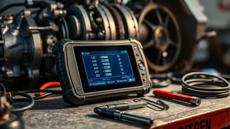
Step-By-Step: Using a Manufacturer-Level Scan Tool to Diagnose Security Immobilizer Codes
To diagnose immobilizer codes with a manufacturer-level scan tool, start by safely connecting to the correct diagnostic connector and verify power, ground, and reference signals before data link. Navigate the tool’s Menu to the immobilizer or security path, confirm the active vehicle profile, and check recent activity logs. Retrieve live fault codes, immobilizer history, and timestamped events, validating responses against expected OEM formats. If results mismatch, document, cross-check CAN frames, and proceed with disciplined, repeatable steps for accuracy. Continuous, precise workflow ahead will reveal more.
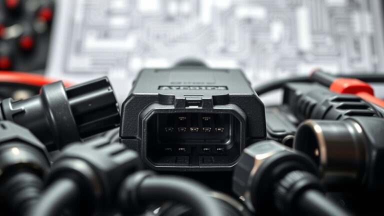
Connecting to the Vehicle’s ECU Safely
Connecting to the vehicle’s ECU safely begins with selecting the correct diagnostic connector and tool, then confirming power and ground are isolated before establishing any data link. You’ll verify the vehicle battery is within normal range and that no active load could cause spikes during connection. Follow strict ecu connection protocols: identify ground reference, inspect pins for damage, and confirm the tool’s compatibility with the ECU family. Avoid energizing the harness until you’ve secured a stable, clean ground and verified no harness shorts exist. Layout a minimal, purpose-built test plan to reduce impedance and noise on the data line. Maintain clean, dry contacts and use protective caps where applicable. Document the connector type, pinout, and tool settings for repeatability. This disciplined approach limits risk, supports reliable data exchange, and lets you proceed to diagnostic tasks with confidence, while keeping emphasis on vehicle battery precautions and accurate ecu connection protocols.
Navigating the Manufacturer Tool Interface

You’ll start by locating the Tool Menu to access core functions quickly. Use the navigation shortcuts to jump between sections like Vehicle/ECU selection and test routines, then verify you’re in the correct module before proceeding. This sets a precise workflow for accessing essential features efficiently.
Accessing Tool Menu
Accessing the Tool Menu is your first step in using a manufacturer-level scan tool. You’ll approach the interface with deliberate, methodical precision, focusing on tool features and predictable menu options. Navigate to the primary dashboard, then confirm device boot and connection status before proceeding.
- Identify tool features visible on the main screen
- Verify the active vehicle profile and module status
- Open the menu options to reveal submenus
- Check for recent activity indicators and logs
- Select the appropriate diagnostic path and confirmation prompts
Your goal is to establish a clean, responsive workspace, ensuring that each action is traceable and repeatable. Stay mindful of security prompts, document results, and preserve freedom by avoiding unnecessary rounds of backtracking. This disciplined approach sets a solid foundation for subsequent steps.
Navigation Shortcuts
Mastering navigation shortcuts starts with a clear mental map of the tool’s layout: know where the main dashboard, tool menu, and submenus live, so you can move quickly without losing context. You’ll exploit consistent key sequences to flip between panels, open recent sessions, and return to the dashboard without retracing steps. In the user interface, establish a habit of using the primary hotkeys first, then secondary ones for context-aware options. Prefer lower-friction paths: left-hand rail for staples, top bar for global actions, and quick-search to summon modules. Keep a mental note of where prompts appear, so you can anticipate confirmations, warnings, or errors. This discipline preserves momentum while you diagnose immobilizer codes with confidence, clarity, and a freedom-oriented workflow. navigation shortcuts enhance efficiency and control within the user interface.
Identifying Immobilizer-Related Diagnostics

Immobilizer-related diagnostics require a structured approach to confirm whether the vehicle’s security system is the source of trouble. You’ll verify presence, status, and interaction with the immobilizer circuits before pulling code interpretations. You aim for untangled results by isolating the relevant modules and confirming the fault path through repeatable checks.
- Identify the target immobilizer module and confirm its communication with the diagnostic tool
- Check power, ground, and reference signals to guarantee pin integrity
- Validate security feature status indicators and fault codes without conflating with other CAN messages
- Test immobilizer challenge/response behavior within safe, authorized limits
- Record timestamped results and correlate with vehicle immobilizer system logs for traceability
This approach keeps you aligned with immobilizer systems and security features, offering a precise, disciplined workflow. You gain clarity, reduce ambiguity, and preserve freedom to troubleshoot confidently without unnecessary detours.
Interpreting Security Code Responses
You’ll compare how security replies are structured across OEM formats, focusing on decoding methods and expected vs. actual values. Next, you’ll examine code response formats to map standard replies to actionable steps, highlighting any mismatches. Finally, you’ll outline troubleshooting paths for mismatched or ambiguous responses to guide reliable diagnosis.
Decoding Security Replies
Decoding security replies requires a precise, methodical approach: interpret each code or beacon within the response, map it to its meaning, and then validate it against the vehicle’s behavior. You’ll cross-check timing, sequence, and status flags to confirm consistency with expected security protocols, ensuring any anomaly triggers a controlled fallback. Focus on robust code validation: confirm that responses align with the immobilizer’s claim and aren’t corrupted by noise or misinterpretation. Maintain a log of decodes and their justifications to support repeatability and traceability. Use defined thresholds to distinguish standard retries from legitimate status changes. Precision here prevents false positives and guides safe, confident decisions about next steps.
- Interpret each beacon in the reply and map it to a defined meaning
- Match timing, sequence, and status flags to expected security protocols
- Validate responses against immobilizer behavior and code validation rules
- Log decodes with rationale for repeatability
- Separate legitimate signals from noise or corruption
Code Response Formats
Code responses arrive as structured messages from the immobilizer or gateway, and direct interpretation hinges on a consistent format. You analyze each reply by examining its code structure: header, payload, and checksum or parity. Establish a baseline template for expected fields, lengths, and delimiters so deviations flag anomalies. In practice, you map response elements to the corresponding security request, then verify integrity with response validation techniques such as checksum verification, length checks, and field-type consistency. Maintain a disciplined log that records timestamps, message IDs, and observed variations. A precise code structure analysis helps you distinguish valid sequences from noise. When formats shift, you pause to reassess parsing rules, avoiding premature conclusions and preserving system freedom through repeatable validation steps.
Troubleshooting Mismatches
When mismatches occur in security code responses, approach them as a structured diagnostic puzzle. You’ll verify data integrity, compare the response against expected patterns, and isolate variance sources without assumptions. Focus on timing, framing, and sequence alignment between the tool and the immobilizer. Document every divergence for traceability, then test under controlled conditions to reproduce the anomaly. Consider how diagnostic equipment compatibility might influence results and whether firmware or protocol handshakes differ from baseline. If responses drift after a security protocol updates, revalidate parameter sets and interpretters before reattempting access. Maintain disciplined logging, version tracking, and repeatable steps to confirm root cause. Keep the process calm, repeatable, and transparent, preserving your tooling freedom while pursuing accuracy.
- Verify data integrity against expected patterns
- Trace timing, framing, and sequence alignment
- Check diagnostic equipment compatibility
- Account for security protocol updates
- Maintain disciplined logging and repeatable steps
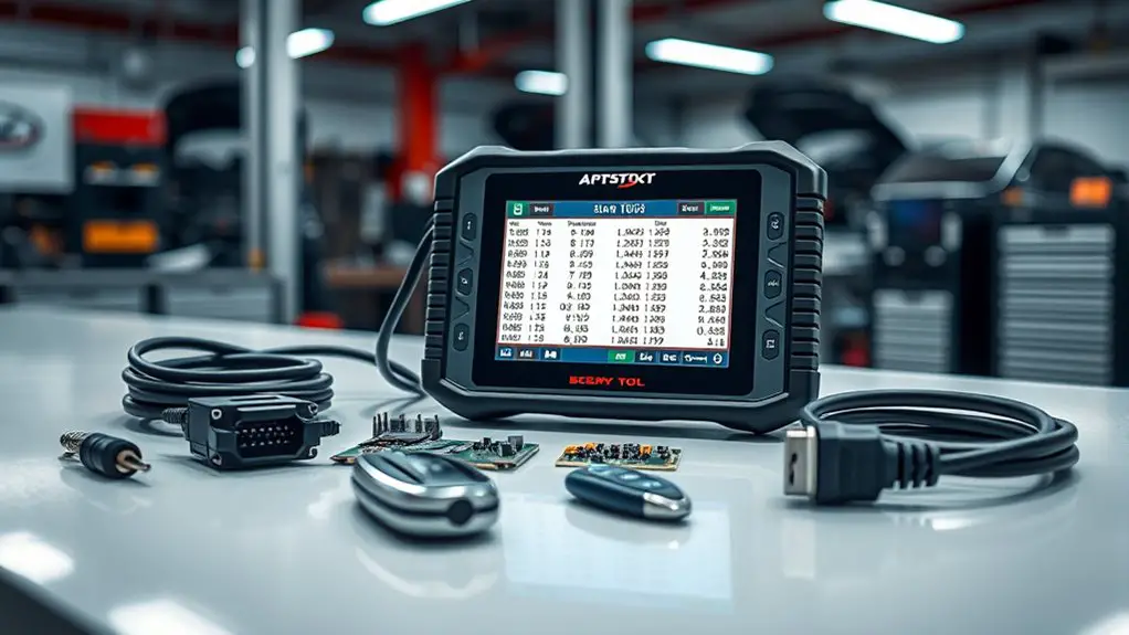
Verifying Fault Codes and History
To verify fault codes and their history, you should first confirm the scanning tool’s current session is connected to the vehicle and that it’s reading the same system you’re evaluating. You’ll perform fault code analysis by filtering active codes from stored ones, noting code numbers, descriptions, and status. Record the timestamp and the module that reported each item, so you can trace origins later. Next, initiate history retrieval to access past events, freeze-frame data, and recently cleared codes. Compare current codes with previous logs to identify intermittent issues or patterns, such as repeating DTCs after ignition cycles. Validate each fault against live sensor data, but avoid assuming causation without corroborating signals. Document any code groups or enhancements the tool provides, and flag codes that require deeper inspection. Maintain a concise, structured log so you can reference results during diagnostics or when communicating with maintenance teams.
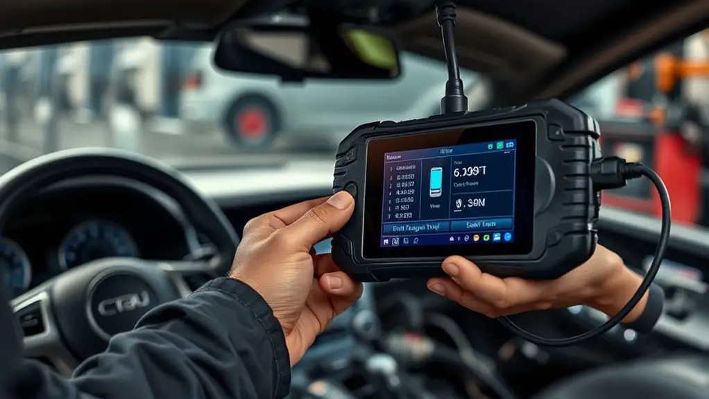
Cross-Checking With Vehicle Communication Protocols
Cross-checking with vehicle communication protocols requires you to verify that the scan tool’s data frames align with the vehicle’s bus traffic. You’ll compare timestamps, message IDs, and payload lengths to confirm coherence between tool output and actual ECUs. Focus on how vehicle protocols encode requests, responses, and error flags, ensuring no frame is misinterpreted as a valid command. This step guards against phantom readings and maintains fidelity to security standards while you pursue legitimate diagnostics. Maintain a disciplined data trail, log anomalies, and document deviations from expected sequences. Precision matters: a single mismatched frame could mask a failure or suggest tampering. Approach with a mindset of verification rather than assumption, and correlate results across multiple buses when available. Your goal is to confirm consistency, not force conclusions. If inconsistencies appear, revalidate tool configuration and consult documented protocol mappings.
Cross-check bus traffic meticulously; verify frame IDs, timing, and payloads against ECUs to ensure consistency and auditability.
- Verify frame alignment with bus traffic
- Compare IDs, lengths, and timing
- Cross-check payloads against ECU responses
- Note any protocol deviations
- Record steps for auditability
Planning Safe Diagnostic Procedures
Planning safe diagnostic procedures requires a structured approach that minimizes risk to personnel and equipment while preserving data integrity. You begin with diagnostic planning: define objectives,Identify relevant vehicle interfaces, and confirm tool capabilities before any connection. Establish a controlled environment, verify power sources, and reserve ignition-off time to prevent transient impacts. Document all safety precautions, including PPE, tool grounding, and secure cable routing to avoid strain or short circuits. Create a written protocol that sequences tool attachment, data logging, and verification steps, reducing improvisation under field conditions. Validate access permissions and log all activity to support traceability. Implement fail-safes for loss of communication or unexpected immobilizer responses, and determine rollback procedures to restore original states. Schedule periodic reviews of the plan, incorporating updates from vehicle documentation and tool firmware. Maintain clear communication with team members, ensuring everyone understands their role, timing, and escalation paths for any anomaly observed during diagnostic planning.
Common Pitfalls and How to Avoid Them
Even with a solid plan, common pitfalls can undermine diagnostic progress, so anticipate them and apply targeted mitigations from the outset. You’ll manage risk by verifying tool compatibility, updating firmware, and confirming vehicle data accessibility before you proceed. Avoid letting diagnostic assumptions drive the workflow; treat each step as verifiable, not presumed. Maintain strict sequence control to prevent cross-contamination of codes or data channels. Document every input and result to preserve reasoning traceability and simplify future audits. Stay aware of common errors, such as misinterpreting immobilizer responses or conflating security codes with ignition status. Practice disciplined test logic: isolate components, repeat key checks, and cross-check with independent sources when feasible. By adopting these practices, you minimize dead ends and keep progress aligned with objective criteria.
- Verify tool Compatibility and Firmware
- Separate Assumptions from Observations
- Exact Data Channel Validation
- Thorough Result Documentation
- Reproduce and Cross-Check Findings
Tips for Accurate Immobilizer Diagnosis and Documentation
To diagnose immobilizer issues accurately, start with a controlled, repeatable approach that separates observations from interpretations and documents every step. You’ll build a traceable workflow that supports diagnostic accuracy and future audits. Begin by confirming tool calibration, vehicle configuration, and ignition state before collecting data. Record sensor statuses, seed-and-key exchanges, and immobilizer system fault codes in timestamped logs, avoiding extrapolation from a single datum. Use cross-checks: correlate CAN messages, ECU responses, and immobilizer prompts across multiple cycles. Separate nuisance indicators from true faults by repeating measurements under consistent conditions. Document environmental factors, accessory loads, and battery health, since these influence signal integrity and interpretation. When conclusions arise, attach rationale, references, and, if applicable, re-test plans. Maintain concise, precise language and standardized terminology to preserve diagnostic accuracy and enable reproducibility by teammates, auditors, or future you. Clarity and discipline empower safe, effective immobilizer system interventions.
Frequently Asked Questions
How Often Should You Update the Tool’s Firmware for Immobilizer Work?
FAQ-focused and factual: you should update the firmware whenever the manufacturer recommends, typically during major releases or security patches, not on a rigid daily schedule. In practice, plan for quarterly or semiannual updates aligned with tool maintenance cycles, plus any critical advisories. This keeps immobilizer work consistent and reduces risk. Maintain a changelog, verify compatibility, and test after updates. Stay vigilant: firmware frequency should reflect risk, reliability, and regulatory expectations for tool maintenance.
Can Immobilizer Codes Be Retrieved Without a Physical Key?
No, immobilizer codes can’t be retrieved without a physical key in most systems. You typically need a valid key or updated key programming data to disengage the immobilizer. You’ll perform key programming procedures or use remote access through the tool to authorize a new key. For safety and legality, you should verify credentials, access permissions, and VIN-specific immobilizer maps before attempting any programming or code retrieval.
What Are the Legal Implications of Bypassing Immobilizers?
Bypassing immobilizers can trigger serious legal consequences, including criminal charges and civil liability. You may face theft, unauthorized access, or equipment tampering violations, plus potential fines and imprisonment. Ethically, it contravenes trust and safety commitments and risks endangering others. Legally, penalties vary by jurisdiction and intent—even attempts matter. If you’re pursuing legitimate diagnostics, obtain proper authorization, keep records, and use approved tools. Seek guidance from a qualified attorney to navigate compliance and protect your freedom to work legally.
How to Verify Tool Calibration Against OEM Security Updates?
You verify tool calibration by cross-checking readings against OEM updates. Start by loading the latest OEM updates, then run a known calibration sequence and compare results to manufacturer-stamped tolerances. Use a secure, documented procedure, log every datum, and confirm with a digital signature. If discrepancies appear, reflash the tool with the latest firmware and re-validate. Maintain traceability, validate against multiple vehicle models, and guarantee your workflow respects licensing and safety standards.
Which Data Logs Are Essential for Post-Diagnosis Review?
You need to record the essential parameters and diagnostic logs during post-diagnosis review. Capture ignition status changes, immobilizer challenge/response timestamps, ECU fault codes, tool session IDs, and timestamped voltage/current readings. Log prior to and after any reflash or key programming, noting loop delays and seed/key verifications. Guarantee data integrity with checksums, secure timestamps, and synchronized clocks. This structured set supports traceability, reproducibility, and a confident validation of security immobilizer diagnostics.