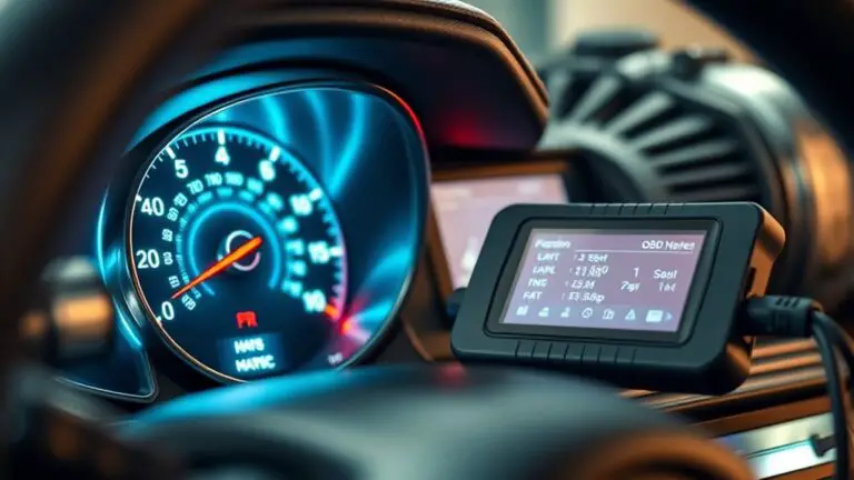
When to Trust the Scanner Vs Understanding Symptoms for No Communication With ECU
When you’re dealing with no communication from the ECU, don’t trust the scanner alone. Use it as a data point, not a verdict, and validate with hands-on checks. Confirm sensor signals, wiring integrity, grounds, and power stability first. Look for repeatable sensor patterns, timing, and voltage behavior, then differentiate wiring faults from ECU faults. If communication gaps persist, isolate the bus, verify connectors, and test with known-good components. Curious what steps come next? more insights await you.
Assessing When the Scanner Might Be Misleading
Even when a scan tool shows normal ECU codes or toastable readiness flags, the scanner can still mislead you about actual engine or system health. You’ll learn to separate data from meaning by examining context, timing, and scope. Scanner limitations include limited code sets, non-CAN diagnostics, and software version gaps that mask actual faults. Diagnostic pitfalls arise when you treat DTCs as definitive truth rather than indicators needing corroboration. Rely on trend data, freeze-frame snapshots, and supported parameter IDs to gauge consistency over a drive cycle. Be wary of false positives from renamed or cleared codes, and beware misinterpreting pending codes as resolved. Cross-check with live sensor data, fuel trims, misfire history, and actuator response to commands. If readings look normal but symptoms persist, document patterns, faktored workarounds, and constraints—then plan targeted tests. This disciplined approach keeps you aligned with reliable diagnostics, preserving freedom through informed, precise decisions.
Recognizing Symptoms That Demand Hands-On Investigation

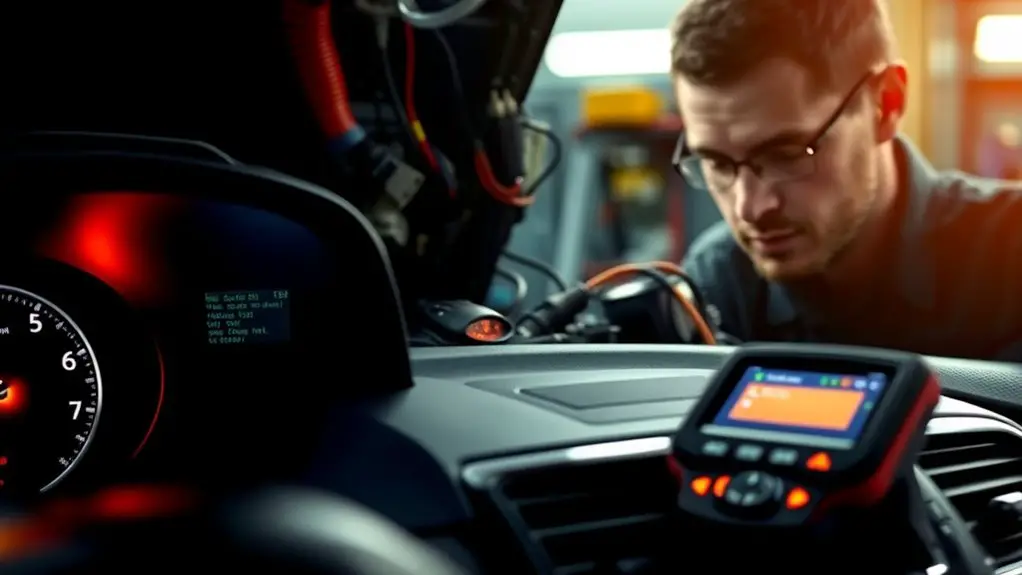
Hands-on indicators emerge when symptoms don’t align with scanner data, signaling an inspection is needed. Look for non-communicative clues, such as inconsistent sensor readings or physical fault symptoms that the ECU can’t explain alone. Together, these signals—hands-on indicators, symptoms requiring inspection, and non-communicative clues—guide you toward targeted, hands-on verification.
Hands-On Indicators
When symptoms point to ECU communication issues, you’ll rely on observable, tangible indicators that diverge from expected scanner data, requiring direct inspection and targeted testing. Hands-on indicators emerge where data mismatches or stalls surface despite normal fault codes. You’ll notice inconsistent sensor behavior, wiring flex under load, corroded grounds, and intermittent connector seating that influences communication reliability. Practical troubleshooting hinges on repeatable checks: continuity tests, pin-to-pin verification, and voltage rails under varying loads. You’ll validate the absence of passive faults by isolating modules and reproducing symptoms in controlled conditions. This approach emphasizes hands on diagnostics over speculation, pairing objective measurements with systematic elimination. The aim is decisive attribution, reducing diagnostic drift, and restoring confidence in ECU performance without unnecessary checks. Freedom in method, precision in result.
Symptoms Requiring Inspection
Certain symptoms signal the need for direct inspection rather than sole reliance on scanner data, indicating potential ECU communication faults that require hands-on verification. When symptoms persist despite clean ECU readouts, you must verify physical layers. Look for sensor malfunction indicators that aren’t resolved by software checks, and confirm proper signal integrity and grounding. Inspect harnesses for chafing, loose connectors, or corroded pins, as these wiring issues can mimic or mask genuine faults. Verify battery voltage stability and ignition noise that could skew readings. Check for inconsistent sensor latency, delayed responses, or sporadic zero-crossings, then map faults to specific circuits. Use controlled tests with known-good components to isolate the issue, prioritizing a methodical, repeatable approach over assumptions. Your goal: eliminate ambiguity through direct verification.
Non-Communicative Clues Together
Non-Communicative Clues Together: when scanner readings don’t align with observed behavior, concrete verification becomes essential. You’ll compare non verbal cues against stored data, isolating discrepancies that pure diagnostics miss. This approach emphasizes hands-on verification: repeat tests, cross-check sensor inputs, and simulate operating conditions to reproduce symptoms. You’ll document every anomaly, because diagnostic challenges often arise from timing, wiring, or intermittent faults rather than a single failing module. Treat incongruent results as a system signal, not noise. Narrow the gap by correlating behavior across subsystems, then verify with direct measurement rather than assumption. In the end, you gain a practical framework for mapping symptoms to roots, balancing scanner insight with real-world observation to reduce uncertainty and maintain freedom through informed action.
Interpreting Diagnostic Trouble Codes With Practical Caution
Interpreting diagnostic trouble codes (DTCs) requires a disciplined approach: treat each code as a data point that points to a probable fault area, not a definitive diagnosis. You’ll map codes to system tendencies, cross-check with recent activity, and consider environmental factors. Rely on scanner reliability as a baseline, but don’t let a single code drive certainty. Instead, perform symptom evaluation concurrently: note when codes appear, under what loads, and after resets. Prioritize repeatable patterns over one-off alerts, and recognize codes can be historical or courtesy flags. Use a concise, logical workflow: verify hardware integrity, confirm referenced sensors, and assess plausibility against vehicle behavior. Document findings to track evolving trends, not isolated events. Remain mindful that codes illuminate possibilities, not absolutes. This mindset keeps you objective, minimizes guesswork, and preserves your freedom to troubleshoot with curiosity rather than haste.
Differentiating Between Sensor, Wiring, and ECU Faults
When you’re distinguishing faults, start by comparing sensor signals versus wiring integrity and ECU responses. Look for consistent sensor patterns that change with electrical noise or harness resistance to separate sensor issues from wiring faults, then verify ECU fault indicators align with expected input ranges. This focused triage—sensor clues, wiring indicators, and ECU signals—narrows the fault domain and guides targeted testing.
Sensor Vs Wiring Clues
Sensor faults, wiring issues, and ECU problems can produce similar symptom patterns, but you can differentiate them by tracing signal consistency and fault timing: sensors typically show repeatable, voltage-based changes tied to a specific input, wiring faults yield intermittent or open/shorted readings that flip with movement or harness tension, and an ECU fault often presents as inconsistent data or a system-wide failure despite healthy sensors and wiring.
- Visualize a steady voltage ramp that mirrors a known input
- Notice readings that bounce when you wiggle a connector
- Expect sudden jumps with harness flex
- Track whether errors stay with a component or follow a harness
- Distinguish isolated sensor drift from global ECU anomalies and plan tests accordingly
ECU Fault Indicators
ECU fault indicators offer a higher-level view that ties together sensor reliability and wiring continuity with the ECU’s own processing behavior. You’ll use this to separate root causes: sensor faults produce biased or out-of-range readings; wiring issues cause intermittent or blank signals; the ECU itself can misprocess data or fail to reference inputs properly. Treat ecu error codes as directional clues, not final verdicts. When codes point to a sensor channel, verify sensor response, wiring harness integrity, and ground references before replacing components. If codes implicate wiring, inspect connectors, insulation, and continuity with a multimeter, then recheck through diagnostic tools. If codes persist after wiring fixes, the ECU may be faulty or programming corrupted. Always correlate with symptoms and functional tests for a precise conclusion.
When No Communication With the ECU Occurs: Immediate Checks
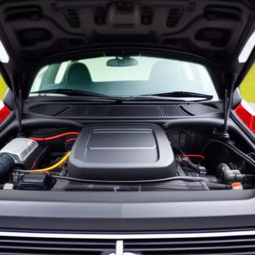
If the ECU isn’t responding, start with immediate hardware and connection checks to rule out simple faults before diagnosing software or wiring issues. You’ll assess interfaces, harness integrity, power supply, and grounding, then verify protocol compatibility and cable condition. This keeps your diagnostics tight, focused, and reversible.
- Loose grounds or corroded contacts that stall signals
- Damaged OBD or harness connectors interrupting communication protocols
- Insufficient battery voltage or unstable ground reference
- Faulty fuses or protective modules misrouting diagnostic data
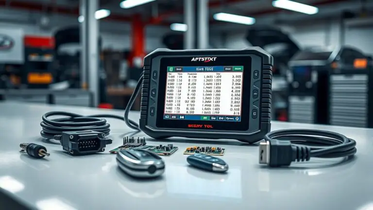
- Incompatible scan tool or software version skewing results
When those checks pass, document readings and proceed with structured diagnostic strategies, ensuring you don’t misinterpret noise as fault codes. Maintain a mindset of minimalism: eliminate the obvious, then interpolate. Your goal is a verifiable, repeatable baseline before deeper analysis, preserving freedom to navigate complex diagnostics without unnecessary risk.
Correlating Idle, Misfire, and Performance Symptoms to Likely Causes
When idle, misfire, or performance symptoms appear, start by mapping the symptom to likely fault classes rather than jumping to a single cause. You’ll model how idle fluctuations, misfire patterns, and performance dips align with core system domains: fuel delivery, ignition, ignition timing, air management, and sensor input. Use symptom analysis to distinguish transient events from persistent trends, then weigh diagnostic accuracy by how consistently readings reproduce the issue across conditions. Correlate idle instability with fuel and vacuum references, link misfire bursts to ignition coil or injector health, and associate performance dips with volumetric efficiency or airflow sensor hints. Avoid leaping to conclusions; instead, build a fault map that prioritizes repeatable correlations over single-point anomalies. Your goal is to narrow candidates efficiently, guiding targeted tests without premature component replacement. This approach preserves freedom to think broadly while maintaining rigor in attributing symptoms to plausible, testable causes.
Validating Sensor Signals Before Replacing Components
Next, validate sensor signals before replacing components to avoid unnecessary parts swapping. You’ll approach sensor validation as a diagnostic gate: confirm signal integrity, timing, and ground references before any component replacement. Treat the ECU as the arbiter of truth; if signals are out of spec, verify wiring harness continuity, shielding, and connector health, then recheck against live data. Focus on correlation between sensor output and expected engineering limits, not guesses. Precision matters: reference ranges, scan tool live data, and multi-sensor cross-checks to distinguish sensor fault from harness or ECU issues. When you’re confident in sensor behavior, you can justify a targeted component replacement rather than broad swaps. Document results clearly to maintain rigour and transparency. This disciplined approach preserves freedom to repair, reduces cost, and elevates reliability through deliberate validation rather than assumption.
- Visualize clean signals tracing through harnesses and grounds
- Compare live data against manufacturer tolerances in real time
- Rule out wiring faults before touching sensors
- Cross-check multiple sensors for consistency
- Replace only after confirming functional thresholds are met
Step-By-Step Approach to Isolating a Communication Gap
To isolate a communications gap, begin by establishing a clear test plan that targets the ECU’s bus, sensor backplanes, and network message timing. You’ll map how data travels, where gaps appear, and what protocol precedes or follows a fault. Use a structured checklist: verify physical connections, confirm power stability, and isolate the bus from modules to rule out collateral faults. Next, run a baseline using known-good messages to define normal timing windows, then compare with failing traces to spot skew, jitter, or dropped frames. Apply targeted troubleshooting strategies: vary load, simulate sensor inputs, and monitor arbitration behavior across communication protocols. Document each deviation, correlating symptoms with timing anomalies rather than assumptions. Maintain a minimal, repeatable sequence to reproduce gaps. Stay disciplined: avoid detours, focus on verifiable evidence, and iterate until you isolate a single fault path. Your freedom comes from precise, evidence-based conclusions.
Translating Scanner Data Into Real-World Troubleshooting Actions
From the baseline and gaps identified earlier, you translate scanner data into actionable troubleshooting steps by mapping every anomaly to a concrete system impact. You don’t chase every spike; you test hypotheses against core functions, sensing how faults ripple through the vehicle’s control loop. Focus on symptom analysis to separate noise from meaning, and acknowledge scanner limitations so you don’t confuse correlation with causation. Build a prioritized plan: confirm the most critical system is healthy, then confirm the next. Link data points to tangible tests, not abstractions, so results guide repair decisions with clarity.
Translate scanner data into actionable steps; test hypotheses on core functions, not every spike.
- A misreadable sensor value becomes a testable diagnostic, not a reason to panic
- A transient fault triggers targeted checks instead of wholesale replacement
- A parameter drift prompts recalibration or software update
- A consistent code with no symptom mismatch flags a systemic review
- Anomalies aligned with known subsystem failures sharpen your path to resolution
Frequently Asked Questions
How Can Scanner Data Be Cross-Checked With Live Sensor Readings?
You can cross-check scanner data by comparing live sensor readings frame-by-frame, watching for drift, lag, or anomalies. Start with scanner calibration, then map each reading against actual sensor outputs under steady states. Look for consistent correlation, recalibrating if deviations exceed tolerance. Use statistics like rms error and correlation coefficients to quantify accuracy. Trustworthy alignment means sensor accuracy stays within spec during tests; investigate discrepancies before relying on the scanner for diagnostics.
What Non-Ecu Symptoms Indicate a Faulty Harness or Connector?
If you notice intermittent misfires, stiffness in starting, or electrical accessories behaving erratically, these non-ECU symptoms point to harness damage or connector corrosion. You might see flickering dashboards, erratic gauge readings, or parasitic drains that don’t track sensor data. Inspect for frayed insulation, loose pins, and corrosion at terminals. A compromised harness or dirty/loose connectors can mimic ECU faults, so verify continuity and clean or replace affected harness segments as needed.
When Should You Distrust a Random Diagnostic Code?
Hope is a broken mirror; you distrust a random diagnostic code when its diagnostic accuracy falters or the code interpretation is inconsistent with symptoms. You should verify against live data, torque history, and multiple scans, not take it at face value. If readings contradict behavior, question the signal. You’ll gain clarity by cross-checking with labors like wiring integrity and ECU communication, embracing disciplined evaluation over quick conclusions.
Can a Misfire Occur Without Any Scanner Alert?
A misfire can occur without a scanner alert. You might see symptoms like rough idle or loss of power even when the ECU isn’t flagging a code. Consider misfire indicators such as uneven firing, vacuum leaks, or degraded spark. Scanner limitations mean some misfires aren’t captured in codes or live data. You’ve got to trust symptoms, test components, and verify with diagnostic methods beyond the scanner for a clear diagnosis.
What Steps Validate a Sensor Before Replacing It?
You validate a sensor by checking signal integrity, response time, and cross-referencing with known-good ranges. Use sensor validation techniques like bench tests, ECU log correlation, and look for faulty sensor indicators such as drift, hysteresis, or out-of-range emissions before replacement. Confirm wiring continuity, grounding, and connector health. If readings align with diagnostic trouble codes and engine performance, you’re justified; otherwise, further tests are warranted. This disciplined approach minimizes unnecessary replacements while ensuring reliability.