Why Your Diesel Truck Heater Fails and How to Diagnose Heater Control Valve
If your diesel truck heater is underperforming, check for coolant flow issues, electrical faults, or a faulty heater control valve. Start by tracing the coolant path to confirm flow to the heater core, then test valve position against engine temperature and load changes. Inspect wiring, fuses, and connectors for corrosion or damage, and verify the control module sends clean signals. If symptoms persist, you’ll uncover steps that reveal more about valve function and seal integrity. More details await.
Common Causes of Diesel Truck Heater Failures
Common causes of diesel truck heater failures typically arise from issues with the cooling system, fuel supply, and electrical controls. You’ll inspect contributing factors methodically to isolate faults without guesswork. The heater core can become clogged or corroded, reducing heat transfer and airflow efficiency. Check for restricted coolant flow, leaks, and persistent low coolant levels, because a compromised loop starves the heater of warmth. Thermostat issues may prevent proper temperature regulation, causing delayed heat or overheating clues. Verify thermostat operation, housing integrity, and gasket sealing to avoid air pockets that hamper heat output. Electrical controls, fuses, relays, and wiring should be tested for continuity and proper voltage; a failing control signal can disable the blower or valve. Airflow obstructions, such as blocked ducts or a malfunctioning blower, degrade performance. Maintain clean coolant, correct concentrations, and secure connections to guarantee predictable operation. Timely diagnosis hinges on separating cooling-system anomalies from fuel-supply and electrical faults to maintain reliable warmth.
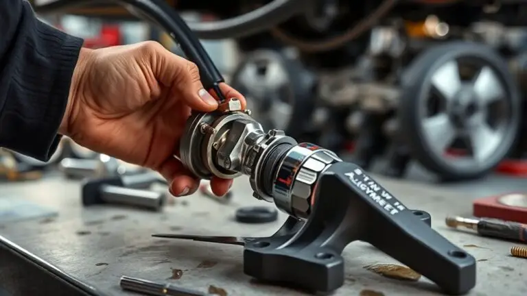
How the Heater Control Valve Works in Diesel Engines
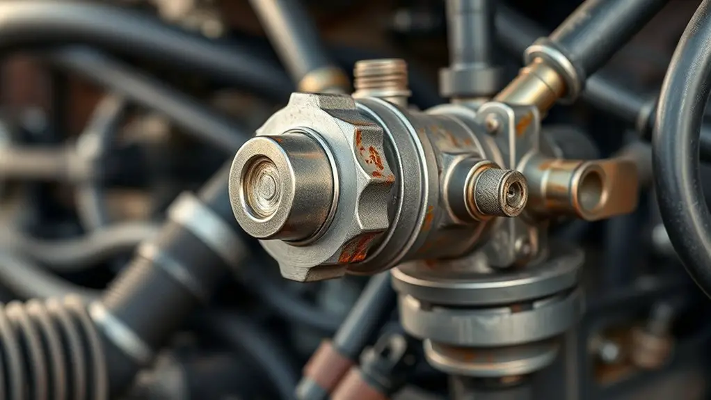
The heater control valve in a diesel engine modulates coolant flow to the heater core, balancing warmth and engine cooling as operating conditions change. You’ll find it inline with the heater circuit, receiving pressure from the water pump and returning to the cylinder head or intake manifold depending on design. Valve operation hinges on a simple actuation: a solenoid or vacuum diaphragm shifts a plunger or flap to open or close the coolant passage. When the demand for cabin heat rises, the valve opens, allowing hot coolant to circulate through the heater core; when cooling or throttle is high, it closes to reduce heat transfer. Reliability relies on clean passages, proper seals, and accurate control signals from the heater switch or engine management. You test the valve by observing flow with the system hot and pressurized, and by verifying that control commands produce the expected opening and closing.
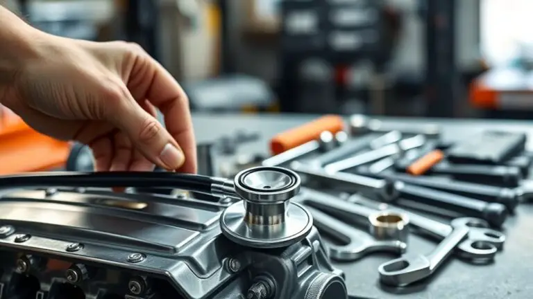
Diagnosing Symptoms That Point to the Valve
If you notice cabin heat inconsistent or delayed, start by confirming that the symptoms align with a valve issue rather than other cooling system faults. Approach this methodically: compare observed heat delivery with expected behavior from the valve’s positions. Look for demands that trigger abrupt temperature swings or failure to reach setpoints at multiple fan speeds. Record symptoms such as partial heating, delayed warm-up, or heat that reverts after acceleration. Perform valve testing by tracing coolant flow path and valve position relative to engine temperature, listening for valve actuator movement, and verifying that vacuum or electrical signals align with commanded states. Eliminate air trapped in lines and verify blend door operation separately if accessible. Correlate timing of symptom onset with engine load changes, since valve faults often manifest under load shifts. If symptoms persist, treat the valve as the root cause of deteriorating heater performance, not ancillary components.
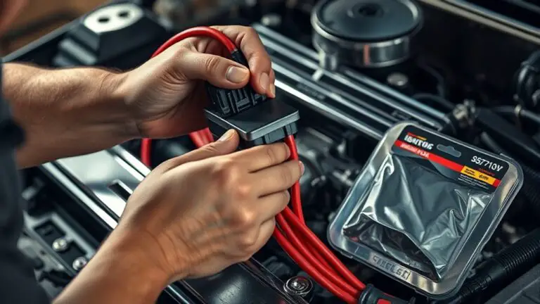
Electrical Issues That Impact Valve Operation
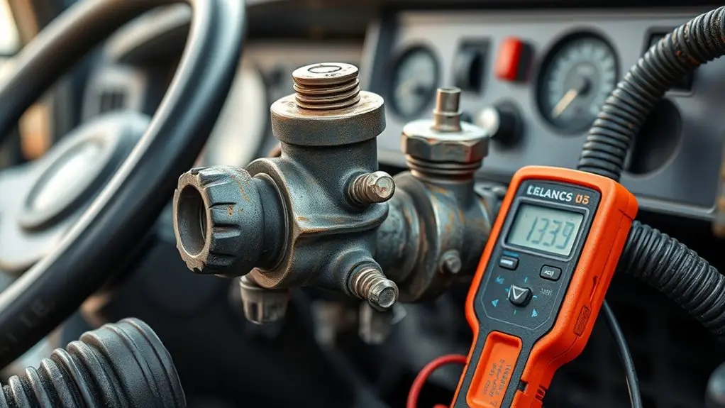
Electrical issues can directly affect valve operation, so after verifying the valve’s mechanical behavior, focus on the electrical pathways that control it. You’ll start with the power source: confirm voltage stability, remove corrosion on terminals, and check for loose grounds that disrupt current flow. Next, test electrical connections for continuity and resistance within tolerance; a high-resistance splice or cracked connector can mute the signal to the actuator. Inspect the valve circuitry itself—watch for damaged windings, burned traces, or degraded insulation that impede response time. The control module or switch must deliver a clean, debounce-free signal; verify proper grounding and absence of voltage spikes. When diagnosing, segregate the signal path from the power path to isolate faults quickly. Document observed symptoms and measured values so you can compare against spec sheets. Correct wiring, solid electrical connections, and intact valve circuitry restore reliable operation and prevent intermittent failures in the heater system.
Coolant Flow and Temperature: What to Check
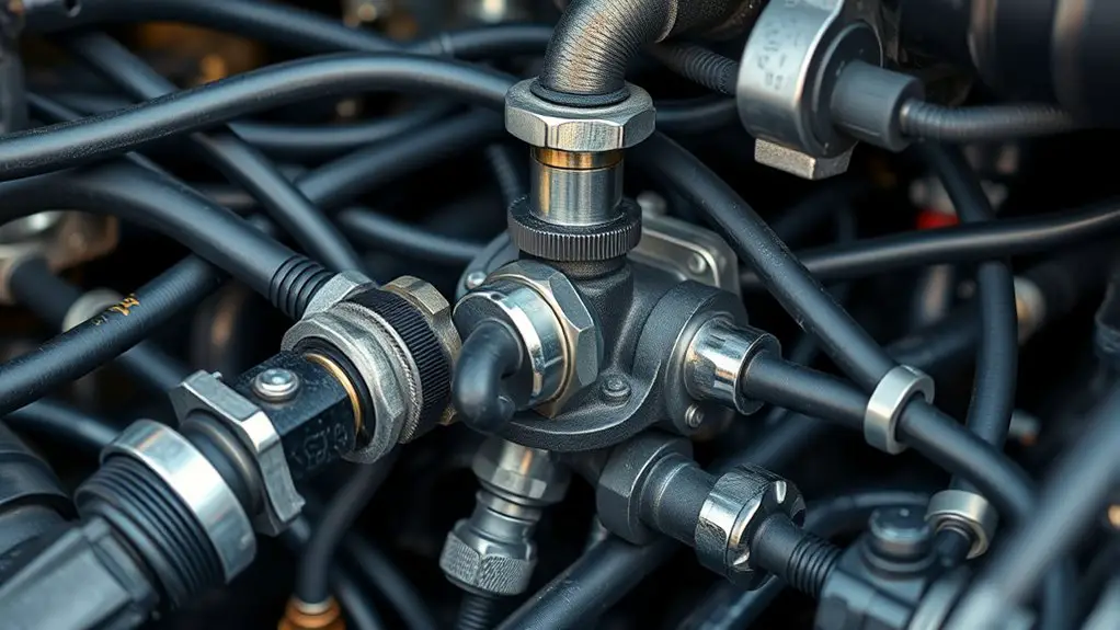
Are coolant flow and temperature behaving as expected, or are readings signaling trouble? You’ll verify core metrics with a calm, systematic approach. Start by checking coolant temperature at the inlet and outlet of the heater core; compare to factory specs and operating range. Small deltas can indicate partial flow issues, while large swings point to restrictions or sensor faults. Next, assess flow directly: feel or measure stream temperature difference across the heater core while the engine reaches operating temperature. If the outlet remains near ambiant or the rise is minimal, suspect flow restrictions or a partially closed valve. Inspect hoses for collapse, kinks, or soft spots that reduce circulation. Inspect the thermostat operation and radiator cap integrity, as these affect overall coolant dynamics. Finally, review the heater core for sediment buildup or external obstructions. Document any deviations and correlate them with perceived heat performance to guide targeted remedies.
Steps for Safe Diagnostic Procedures
To proceed safely from evaluating coolant flow and temperature, establish a controlled diagnostic workflow. You’ll define objectives, list required diagnostic tools, and sequence steps to minimize risk. Begin with documenting baseline readings, then verify electrical connections and fuse integrity before applying power. Use diagnostic tools to monitor sensor feedback, heater control valve position, and actuator current, ensuring readings are within spec. Establish lockout/tagout procedures to prevent accidental startup, and wear appropriate PPE for hot surfaces and moving parts. Proceed with gradual power application, observing for abnormal heat, noise, or smells; halt if symptoms appear. Keep the engine and heater system at safe temperatures, and avoid forcing components beyond their rated range. Maintain a clean work area, label wires, and segregate high-voltage or high-current circuits. Safety precautions should be reviewed before each test, and you should record all results for traceability. Plan exit criteria for early cessation if unexpected conditions arise.
When to Test for Valve Function and Seal Integrity
Valve function and seal integrity should be tested after confirming baseline electrical and hydraulic readings and only when the system is hot or cold as specified by the manufacturer. You’ll verify valve response with the ignition state and heater controls, then observe actuator movement, flow direction, and temperature changes at outlet points. Perform seal checks by inspecting gasket seating, shaft seals, and wiring harness integrity for stiffness, corrosion, or arcing. If readings deviate from spec, document the exact condition and follow a controlled test sequence to isolate variables, ensuring heat or cold cycles reproduce the same results. Record timing, actuator travel, and valve position relative to commanded inputs. This process confirms functional readiness and identifies leaks or binding before proceeding to maintenance tasks. Prioritize safety, repeatability, and traceability to support reliable diagnosis and future service decisions.
Confirm baseline readings, verify actuator travel, and document cycle-specific results to ensure valve integrity and safe maintenance.
- Confirm baseline readings before testing
- Validate actuator travel and seal seating
- Note cycle-dependent anomalies for traceability
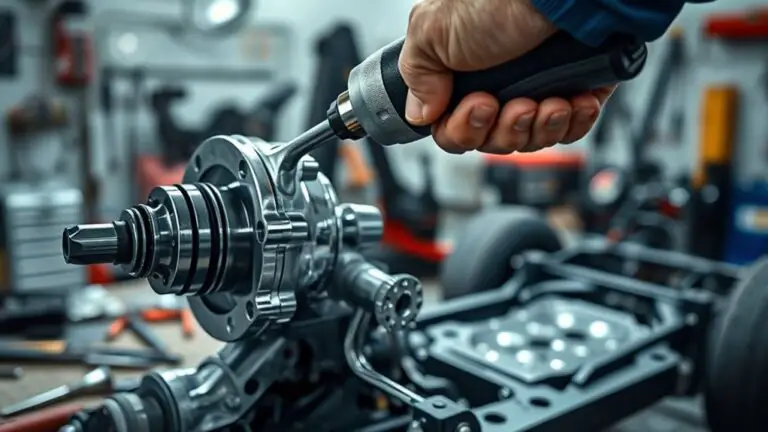
Replacing or Repairing the Heater Control Valve
With baseline readings established and functional checks completed, you’ll move into replacing or repairing the heater control valve. You’ll assess valve integrity, access routes, and mounting hardware, then choose a path: valve replacement tips or targeted repair techniques. If replacing, select an OEM or quality aftermarket valve, depressurize system, disconnect battery, drain coolant, and cap lines to prevent contamination. Install with proper torque, verify fit, then refill and bleed air until steady heat returns. If repairing, inspect seals, actuators, and by-pass passages; reseal or swap internal components only if you can keep calibration intact. Post-install, run through heat cycles and monitor for leaks, proper valve position, and no dash indicator faults. Document procedures for future reference and test under load. Valve replacement tips and repair techniques both demand clean work, precise alignment, and verification of heat output.
| Step | Focus |
|---|---|
| 1 | Preparation |
| 2 | Execution |
| 3 | Verification |
Preventive Maintenance to Avoid Future Failures
Preventive maintenance is essential to extend the heater system’s life and prevent unexpected failures. You’ll reduce risk by scheduling disciplined care, not reactive fixes. Focus on preventive checks and routine inspections that catch wear before it harms performance. Keep the heater core, hoses, and valve connections clean and accessible so you can verify seals and torque without guesswork. Establish a cadence: quarterly checks for fluid levels, electrical harness integrity, and thermostat operation; annual tests for vacuum lines and actuator response. Document results to track trends and plan replacements before they fail. Use quality fluids and filters that meet spec, and replace worn clamps to prevent leaks. When testing, simulate cold-start conditions to confirm valve timing and heater control signals respond promptly. Your goal is predictable heat, minimal downtime, and maximum system longevity.
Schedule quarterly checks, track trends, and replace worn clamps to ensure reliable, long-lasting heater performance.
- Schedule preventive checks and routine inspections with traceable records
- Verify seals, connections, and actuator diagnostics regularly
- Use quality consumables and monitor performance trends diligently
Frequently Asked Questions
Can a Faulty Heater Valve Affect Engine Warming Time?
A faulty heater valve can slow engine warming, you’ll see longer warm-up and reduced heater performance. Yes, it can affect engine efficiency because coolant routing is altered, causing cooling loop inefficiencies. Inspect valve operation, actuator response, and vacuum or electrical signals. If the valve sticks open or closed, coolant flow is unbalanced, delaying heat buildup. Systematic testing improves heater performance and keeps engine efficiency on target. Keep diagnostics precise, methodical, and data-driven. You’ll regain freedom in operation.
Do Exterior Weather Conditions Impact Valve Operation?
Exterior weather conditions can affect valve operation. You’ll notice tighter tolerances during temperature fluctuations that stress seals and actuators. To minimize impact, perform regular valve maintenance, inspect hoses for stiffness, and guarantee bedding is stable. Keep connections clean and free of corrosion. Monitor for binding as temps swing, and recalibrate if needed. By addressing valve maintenance proactively, you preserve consistent temperature control despite weather shifts and reduce unexpected heater failures.
Can Air Pockets in Coolant Mimic Valve Failures?
Air pockets can mimic valve failures, yes. You’d notice uneven coolant circulation and fluctuating temps when trapped air blocks flow, just like a faulty control valve. You’re chasing symptoms of air pocket symptoms: intermittent heater output, sudden heat loss, or gauge spikes. Check for burping, bleed procedures, and proper coolant level. In practice, diagnose with a careful purge, monitor flow, and confirm consistent circulation to avoid misattributing a coolant-air issue to valve failure.
Is the Valve Field-Serviceable Without Special Tools?
Yes, you can field-service the valve without special tools, but proceed carefully. Use basic hand tools, a flashlight, and a clean workspace. Follow valve maintenance tips: disconnect power, relieve pressure, and test movement with clean fluid. For troubleshooting techniques, verify actuator alignment and actuator wiring, inspect seals, and check for leaks. Document steps, avoid forcing components, and re-seat firmly. If uncertain, consult service manuals and safety procedures to prevent damage.
How Does Vehicle Age Influence Valve Reliability?
Vehicle age tends to reduce valve reliability as seals and housings wear. You’ll notice harder actuations, slower response, or leaks that worsen with mileage. Over time, valve material softens or cracks, and corrosion accumulates in passages. Your maintenance history matters: earlier, regular service keeps internals clean and seals intact, while gaps in servicing accelerate failure. Track wear, replace worn components, and document maintenance to predict remaining life and avoid unexpected heater loss.