Common Wiring Faults That Cause Fault Codes After Battery Disconnect in Safety Systems
After a battery disconnect, you’ll likely see fault codes from loose or damaged connections, grounding or bonding lapses, insulation damage, or misrouted circuits. Check critical joints for corrosion, frayed wires, and bent pins, then reseat connectors and test under load. Verify low-resistance grounding paths and inspect bonded conductors for continuity. Trace circuits to prevent crosstalk and confirm proper routing. Document anomalies and apply systematic tests to avoid false positives; more details await if you continue.
Common Causes of Post-Disconnect Faults in Wiring
Post-disconnect faults in wiring typically arise from a combination of mechanical stress, insulation degradation, and improper reconnection practices. You’ll map how each factor undermines reliability, then prioritize fixes that restore wiring integrity and connection stability. Mechanical stress—bends, twists, or pinches—weakens conductors at joints and strain-relief points, creating micro-cracks that later fail under load. Insulation degradation—aging, chemicals, heat, or UV exposure—lowers dielectric strength, increasing leakage paths and arc risk. Improper reconnection practices, including loose terminals, mixed gland seals, or reversed polarity, introduce intermittent contacts that mimic software fault codes or sensor errors. You’ll verify termination tightness, inspect sheath integrity, and confirm correct connector orientation, documenting changes for traceability. During repairs, maintain consistent torque specs and use compatible materials to preserve electrical margins. By prioritizing systematic checks, you sustain wiring integrity and connection stability, reduce post-disconnect anomalies, and support predictable system performance, while empowering you to pursue safer, freer operation through disciplined maintenance.
Detecting Loose and Damaged Connections After Repowering
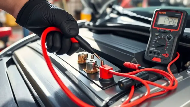
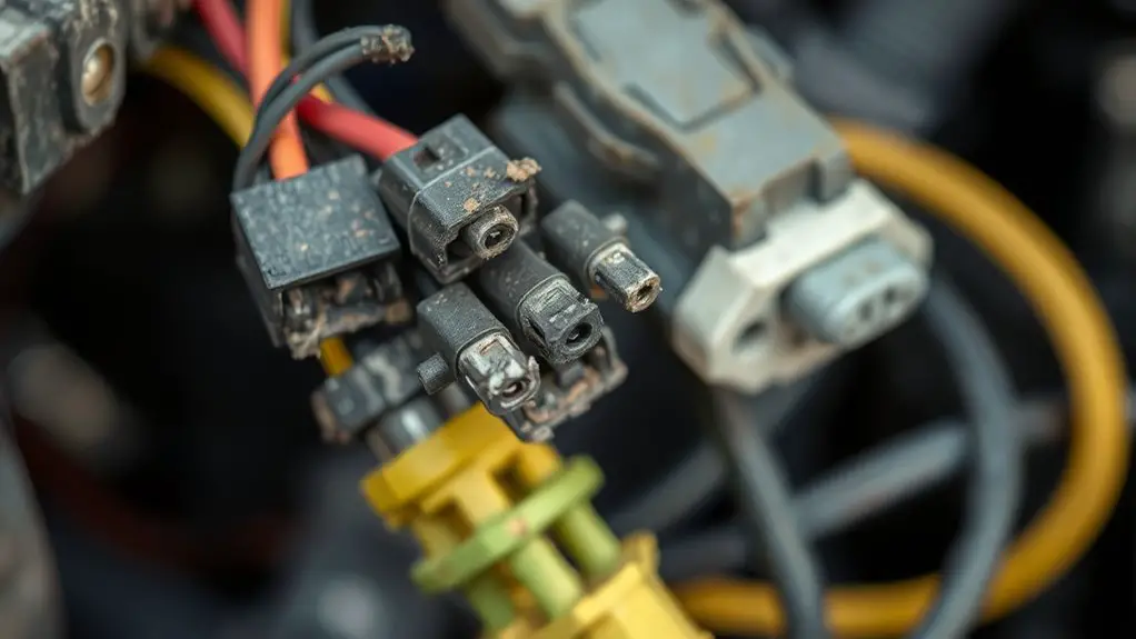
After repowering, start with a controlled check for looseness and damage by testing each critical connection point under load and at rest. You’ll verify that terminal blocks, harness pins, and ground lugs seat firmly and show no play. Perform a step-by-step inspection: inspect connectors for corrosion, fraying, or bent pins; confirm shielded cables remain intact; and confirm fasteners are torqued to spec without over-tightening. Proceed with connection testing under typical operating current to detect intermittent contact that only appears under load. Then repeat with the system at idle to catch high-resistance paths that vanish when current flows. Document any marginal readings and re-seat or replace parts as needed. Maintain consistent test conditions and compare results against baseline. Use a continuity assessment to ascertain continuous paths exist where expected. This disciplined approach helps you preserve reliability while preserving freedom to troubleshoot.
Grounding and Bonding Issues That Trigger Alarms

You’ll examine how grounding integrity lapses and bonding conductor faults can set off alarms, pinpointing where the fault originates. Start by mapping the path from grounding electrode to the system return, noting any impedance changes that elevate fault currents. Then assess bonding connections for continuity and low resistance, documenting any gaps that could trigger false or missed alarms.
Grounding Integrity Lapses
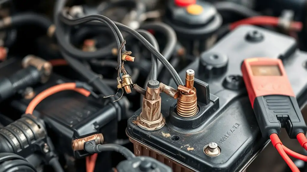
Grounding integrity lapses occur when the reference path or bond between equipment and earth is compromised, causing false alarms or missed safety signals. You’ll check for clean, continuous connections and verify that impedance remains within spec. System health depends on stable reference potential, so inspect grounding techniques for proper routing, shielding, and isolation where required. Look for corrosion, loose terminals, and damaged conductors, and document any deviations from the established ground scheme. Ascertain grounding equipment meets design tolerances and is compatible with the environment, including moisture, chemical exposure, and vibration. Use calibrated testing to confirm low-resistance paths and promptly remediate any increases. Maintain a concise log of findings, actions taken, and residual risk, so alarms reflect true conditions and you preserve operator confidence.
Bonding Conductor Faults
Bonding conductor faults can trigger alarms when the bond between equipment and the earth or between metallic enclosures isn’t solid or compliant. You’ll verify connections at each enclosure, ensuring low-resistance paths to earth and proper bonding to auxiliary structures. Inspect for loosened screws, corroded lugs, or degraded conductors, and replace as needed to restore continuity. Document all Bonding points, confirming that clamps, straps, and jumpers meet recognized bonding techniques. Test continuity with appropriate instruments, recording resistances that meet defined thresholds for your system. Consider environmental factors: vibration, moisture, and thermal cycling can loosen bonds over time. Schedule regular conductor maintenance, prioritizing critical safety paths and redundant bonds where applicable. Maintain an auditable trail of tests, findings, and remediation steps to sustain reliable fault code behavior.
Insulation Damage and Short-Circuit Risks Post-Power Restoration
After power restoration, insulation damage can silently create dangerous short-circuit conditions; remaining faults may only become evident once currents surge. You’ll want a disciplined approach: inspect exposed conductors, verify insulation integrity, and note any nicks, cracks, or softened areas. Surface flaws can hide deeper breaches that escalate under load, so treat every irregularity as a precursor to fault codes. Follow a systematic check: isolate the circuit, perform continuity and insulation resistance tests, and compare readings against manufacturer specs. Document environmental factors—temperature, humidity, and vibration—that may stress insulation after reconnection. Prioritize short circuit prevention by addressing compromised sections before re-energizing, and guarantee protective devices are calibrated to detect abnormal currents promptly. Maintain a log of findings to drive ongoing reliability. You’re aiming for controlled restoration, where every connection preserves insulation integrity and reduces the risk of sudden faults, preserving safe, functional operation.
Misrouted Circuits and Wiring Crosstalk After Reconnection
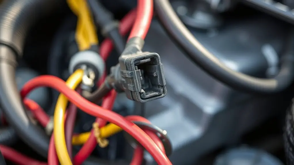
Misrouted circuits and wiring crosstalk often surface after reconnection when unintended conductors share pathways or receiver points are misallocated. You’ll investigate with a methodical mindset, tracing routes and confirming endpoints before energizing. Focus on circuit tracing to prevent mislabeling and guarantee each signal lands where it should. Crosstalk emerges when adjacent wires couple fields, so keep parallel runs brief and segregate power from data lines. Document each step, verify harness integrity, and test with controlled energization to observe any signal interference patterns.
| Step | Action |
|---|---|
| 1 | Map all connections and confirm receiver allocations |
| 2 | Inspect bundles for tightness and separation |
| 3 | Validate signaling paths under load, noting anomalies |
Use these checks to minimize ambiguity and maintain operational freedom. When doubt arises, pause and re-map rather than push forward. Precision in wiring discipline protects safety networks and supports confident re-closure after disconnection.
Systematic Diagnostics for False Positives in Safety Networks
You’ll start by identifying common false positive patterns in your safety network and documenting their triggers. Then, you’ll implement a structured diagnostics approach, focusing on isolating false positives after disconnects and verifying system responses. Finally, you’ll use this data to refine your diagnostics workflow, ensuring repeatable, low-noise detection without impacting safety compliance.
False Positive Patterns
False positive patterns occur when diagnostic signals indicate a fault that isn’t actually present, leading you to chase non-existent issues. You’ll map symptoms to specific fault codes, then test in a controlled sequence to rule out noise, grounding issues, and timing glitches. Approach each pattern with a hypothesis, not a conclusion, and document every step for traceability. Focus on false alarms that emerge after transient events, load changes, or firmware quirks, and differentiate them from genuine degradation. Track intermittent signals by correlating date stamps, sensor readings, and network traffic, ensuring you don’t overreact to short-lived spikes. Adopt a conservative threshold strategy: confirm with repeatable observations before invoking repairs. This disciplined pattern keeps you from unnecessary interventions while preserving system safety and operator trust.
Diagnostics After Disconnect
When a node or link is disconnected, start with a controlled diagnostic sequence to distinguish intentional removal from latent false positives. You apply systematic testing to confirm fault codes reflect real faults, not transient anomalies. Use diagnostic tools to verify continuity, resistance, and isolation, then compare results against wiring standards. Document each step to guarantee repeatability and traceability. If codes persist, re-check power sequencing and ground references before reasserting normal operation. Maintain a disciplined record to support safe decisions and clear rollback procedures. Table below conveys core concepts succinctly.
| Step | Action | Verification |
|---|---|---|
| 1 | Isolate | Confirm isolation using diagnostic tools |
| 2 | Measure | Compare readings to wiring standards |
| 3 | Validate | Reconnect and retest for consistency |
Frequently Asked Questions
How Do EMI Filters Influence Post-Disconnect Fault Codes?
EMI filters influence post-disconnect fault codes by shaping transient behavior and noise immunity. You’ll see smoother EMI performance because properly designed filters limit high-frequency surges that trigger false faults. Filter design matters: the right cutoff, attenuation, and grounding reduce residual noise that your safety system might misinterpret. You’ll gain clearer diagnostics, fewer spurious codes, and more predictable behavior. In practice, validate with controlled disconnect tests to confirm consistent EMI performance and reliable fault-code reporting.
Can Software Calibration Cause False Alarms After Battery Reconnection?
Software calibration can trigger false alarms after reconnection if calibration errors occur. You’ll want to verify software updates are current and that new firmware hasn’t introduced timing or checksum glitches. Check the calibration against baseline references, revalidate sensor offsets, and perform a controlled reboot to clear transient flags. If alarms persist, document the exact sequence, rollback to a stable version, and re-run tests. You seek freedom, so insist on reproducible, artifact-free status before operation.
Do Sensor Wake-Up Sequences Affect Immediate Fault Code Generation?
Sensor wake-up sequences can trigger immediate fault codes if wake up thresholds aren’t met or are crossed too quickly. You should verify that sensor activation aligns with expected timing, avoiding premature reads right after reconnection. Maintain clear margins for wake up thresholds and implement debounce logic to prevent false alarms. By methodically tuning activation windows, you preserve system freedom while ensuring reliable fault detection without unnecessary interruptions.
Are Rotary Switches Prone to Misreadings After Power Restoration?
Rotary switches can misread after power restoration if contact wear or improper calibration exists. You should verify rotary switch calibration and inspect contact wear before assuming a fault. Start with a controlled power-up, then test each position for consistent readings. If readings drift, replace worn contacts or recalibrate. Regular maintenance reduces drift, ensuring reliable signals. This approach respects your freedom to troubleshoot methodically and confirms you’re not blaming the system, only addressing root causes.
What Role Do Surge Suppression Devices Play in Misdiagnosed Faults?
You ask: surge suppression devices can prevent misdiagnosed faults by filtering transients and stabilizing voltage, but they won’t fix wiring integrity issues or non-ideal connections. You’ll rely on proper placement, grounding, and matching surge protection ratings to equipment. Treat misreads as symptoms, not causes. When used correctly, surge protection reduces nuisance fault codes, yet you must verify wiring integrity to guarantee accurate diagnostics and avoid false positives during power restoration.