Cost and Time Estimate to Fix AC Cycles on and off
You’ll get a clear, data‑driven plan for diagnosing and fixing your AC cycling on and off, with realistic on‑site time estimates and transparent parts costs. Start with a 0.5‑hour initial inspection, then 1.0 hour for electrical checks, and 0.5 hour for performance verification. Expect parts like wiring harnesses, sensors, or control boards to run $20–$150 each; motors or compressors vary widely. If needed, refrigerant adds $35–$120 per pound. More steps ahead can reduce repeat cycling—keep reading for details.
Understanding Why AC Cycles Off and On

Air conditioning units cycle on and off to maintain the set temperature while keeping the compressor under load and the system from overworking. You’ll notice short periods of cooling followed by pauses, which helps balance efficiency and comfort. The core idea is that the system responds to small temperature errors and external conditions by modulating activity rather than running flat out. AC cycling causes can include thermostat placement, improper load, and refrigerant pressures that aren’t ideal. Temperature fluctuations arise when the outdoor temperature, sun exposure, or occupancy levels shift faster than the unit can compensate. Another factor is duct leakage or blockage, which changes airflow and makes the conditioned space less stable. To diagnose, monitor runtime versus setpoints, confirm that the thermostat senses accurately, and verify airflow. With precise measurements, you can identify whether fixes are mechanical, electrical, or related to refrigerant charge, and plan targeted maintenance or replacements accordingly.
Diagnosing Power and Thermostat Issues
Start by checking power signals to confirm the thermostat and control board are getting clean, stable voltage during cycles, recording any voltage dips or interruptions. Then examine thermostat control clues—verify settings, sensor readings, and wiring integrity to pinpoint if a faulty sensor or loose connection is triggering unnecessary cycling. Finally, map the cycling pattern to likely causes, using data like restart delays and compressor lockouts to distinguish power issues from thermostat problems.
Diagnosing Power Signals
Diagnosing power signals begins with a clear read of the thermostat and control board voltages, wiring states, and signal timing. You’ll map expected vs. actual voltages, confirm common-mode or ground references, and note repeatable cycles. Focus on clean data: measured exact values, tolerances, and timing windows for each relay and sensor input. Use a structured approach to power signal analysis: verify supply rails, check for floating inputs, and correlate readings with system behavior under call-for-heat or cool. Document anomalies, then isolate whether the issue stems from control wiring, harness integrity, or a failing component. This electrical signal troubleshooting mindset helps you determine root causes quickly, enabling precise fixes and reducing unnecessary replacements.
Thermostat Control Clues
Thermostat control clues—often the most telling fingerprints of power and thermostat issues—start with a careful read of voltage rails, reference grounds, and the thermostat’s demand signals across heat and cool cycles. You’ll trace whether the control board sends clean, consistent signals or shows chatter, which hints at wiring faults or a marginal supply. Check the thermostat calibration to guarantee the device translates room temperature into accurate calls for heat or cool; a mismatch here skews cycles and wastes energy. Inspect temperature settings for unexpected offsets, and confirm that setpoints align with actual room readings. Document any drift over time, and verify that sensors respond promptly to changes. Accurate calibration and clear temperature settings empower faster fixes and steadier, freedom-loving comfort.
Cycling Cause Identification
To identify cycling causes, you’ll first map how power and thermostat signals interact during heat and cool calls, noting any irregularities in voltage, grounds, or control board communications that coincide with on/off cycles.
| Power signal | Thermostat response | Likely issue |
|---|---|---|
| Stable voltage | Proper call signals | Normal cycling |
| Fluctuating voltage | delayed/erratic calls | Cycling frequency spike |
| Ground fault | misreads | Sensor/PCB fault |
| Control board chatter | rapid on/off | Low energy efficiency |
| Damper/relay mismatch | uneven cycling | Mechanical snag |
Focus on data: voltage logs, ground continuity, and board diagnostics. Quick fixes target obvious faults, while persistent patterns indicate sensors or boards needing replacement. Track cycling frequency trends; improvements often boost energy efficiency and comfort.
Inspecting Refrigerant and Charging Levels

Inspecting refrigerant and charging levels is a critical step because improper amounts can cause short cycling, reduced cooling, and compressor damage. You’ll verify charge against factory specifications, then measure pressure and superheat to confirm proper refrigerant mass. Start with a visual check for refrigerant leaks, listening for hissing sounds and inspecting connections, service ports, and lines for oil stain or corrosion clues. If a leak is suspected, repair it before charging to avoid rework. Use calibrated gauges and a proven charging technique, following manufacturer guidance and local codes. Document intake and outlet pressures, ambient temperature, and desired superheat range; deviations guide whether you’re under- or overcharged. When adding refrigerant, do so in small increments, pause to recheck pressures, and avoid overcharging, which can raise head pressure and reduce efficiency. After charging, recheck all operating parameters and note any anomalies. This approach supports controlled, data-backed decisions and minimizes repeat visits.
Evaluating Capacitor, Contactor, and Electrical Components
After confirming refrigerant and charging accuracy, you’ll want to turn your attention to the electrical side: capacitor, contactor, and related components. You’ll assess capacitor health with capacitor testing, looking for swelling, leakage, and ESR deviations, then compare against spec sheets. For the contactor, inspect for pitting, welded contacts, and excessive bounce; note coil resistance and coil voltage compatibility. Document cycle behavior during energize/de-energize and record any audible chattering. Use this data to decide if capacitor replacement or contactor replacement is warranted, prioritizing components with the highest failure likelihood and the greatest impact on cycling reliability.
| Factor | What to measure |
|---|---|
| Capacitance health | Capacitance value vs. rated spec, leakage current |
| Contact resistance | Contact wear, coil resistance, mechanical sticking |
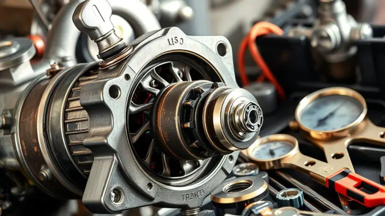
Diagnosing Compressor-Related Causes
Compressor-related faults often lie at the heart of cycling issues, so start with a structured fault-hypothesis approach: confirm compressor operation under load, measure current draw, and compare against nameplate data to distinguish under- or over-compression, stuck valves, or failed cycling. You’ll verify suction and discharge pressures, listen for abnormal noise, and inspect mount integrity for vibration-induced faults. Record baseline amperage at rated voltage and note any deviations during cycles; a high draw with low head pressure points to overload or compressor wear, while low draw may signal suction restriction or failed starting components. Evaluate compressor types in your system—reciprocating, scroll, or screw—and match symptoms to typical failure modes. Plan targeted maintenance actions: tighten or replace worn valves, clear blockages, and confirm refrigerant charge is correct. Document results, troubleshoot methodically, and update maintenance schedules to prevent recurrence—compressor maintenance is your frontline defense against erratic cycles and downtime.
Labor Time: Estimating On-Site Diagnosis and Repair
When you move from diagnosing compressor-related faults to estimating on-site labor, you shift from identifying symptoms to mapping time, sequence, and cost. You’ll quantify labor efficiency by tracking diagnostic steps, repair tasks, and test iterations, then translate them into realistic on-site hours. Use diagnostic tools to confirm faults quickly, minimizing wasted trips and rework. Build a time model that assigns each action a fixed duration and a contingency buffer for unknowns. Record the sequence: initial inspection, electrical checks, refrigerant verification, component testing, and final performance verification. This approach yields precise estimates and actionable benchmarks.
| Step | Task | Estimated Time (hrs) |
|---|---|---|
| 1 | Initial inspection | 0.5 |
| 2 | Electrical & control checks | 1.0 |
| 3 | Diagnostics with tools | 1.0 |
| 4 | Performance verification | 0.5 |
This framework supports transparent pricing, aligns with labor efficiency goals, and leverages diagnostic tools for faster, freer work outputs.
Parts and Materials: Common Costs for Fixes
In this section, you’ll map the typical parts and materials that show up in AC repair jobs, with concrete cost ranges and substitution guidance. You’ll see replacement parts priced by function, not brand, so you can compare options quickly. Expect common components like capacitors, contactors, relays, and contact-set switches with material costs in the ballpark of $5–$25 for small parts and $25–$120 for high‑quality, longer‑life pieces. Fans, motors, and compressors carry higher ranges, roughly $75–$350 for motors and $400–$1,800 for compressors, depending on size and efficiency. Refrigerant is priced per pound, often $35–$120, plus cylinder service fees. Labor‑related component pricing covers wiring harnesses, sensors, and control boards, typically $20–$150 per item. For repair services, expect diagnostic charges offset by parts, with total job costs framed by the part mix and replacement frequency. Plan for substitutions to balance reliability and cost.
Preventive Steps to Reduce Future Cycling Problems
Regular preventive steps can considerably cut cycling problems by addressing the root causes: dirty filters and coils, improper refrigerant charge, and worn electrical connections. To begin, commit to preventive maintenance every season: replace or clean filters, inspect coils for frost or dirt buildup, and verify airflow and duct integrity. Next, confirm refrigerant charge matches manufacturer specifications; under- or overcharging triggers short cycling and efficiency losses, so measure pressure with proper gauges and adjust as needed. Then, test electrical components for loose connections, worn contactor points, and capacitor health; faulty hardware can cause intermittent cycling and voltage dips. Schedule regular inspections of the thermostat and control board to guarantee correct cycling thresholds and sequencing. Document findings and track corrective actions, costs, and time to resolve issues. By prioritizing preventive maintenance and routine inspections, you gain reliability, energy savings, and fewer surprise breakdowns—empowering your freedom to live without constant HVAC uncertainty.
Frequently Asked Questions
How Long Does a Typical AC Cycling Repair Take Onsite?
Repair duration for an onsite AC cycling issue typically runs a few hours, depending on root cause and access. You’ll often see 2–4 hours for a full diagnostic and core repairs, with potential extensions if parts are needed. Keep in mind technician availability can shift timing. Track your schedule, request proactive updates, and have a contingency plan. If timelines stretch, ask for confirmation of ETA and alternative options to minimize downtime.
Which Thermostat Settings Trigger Unnecessary Cycling?
Setting thermostat settings that trigger unnecessary cycling include very short or very long temperature hold ranges, sudden setbacks, and aggressive fan modes; avoid them. Calibrate your thermostat to the true average room temperature, and monitor cycling frequency after changes. When you see rapid on/off, adjust Hysteresis and verify sensor placement. Regular thermostat calibration helps reduce cycling frequency while preserving comfort, efficiency, and freedom to tailor comfort zones.
Do Refrigerant Leaks Always Require a Full Charge Replacement?
Refrigerant leaks don’t always require a full charge replacement, but often you’ll need a targeted repair and recharging of the affected circuits. You’ll want to identify refrigerant types, locate the leak (leak detection), repair it, and then pressure-test. If the system saw significant loss, a full charge might be necessary. Stay data-driven: document leak rate, use appropriate tools, and verify with a quality vacuum pull and final charge for reliable performance.
Can Low Voltage Supply Cause Frequent Cycling?
Yes, low voltage supply can cause frequent cycling. When voltage fluctuates, your compressor may start and stop to protect components, leading to uneven cooling. To diagnose, monitor voltage levels at the air handler and main panel, note any cycling patterns, and check for loose connections or undersized wiring. Address voltage fluctuations by stabilizing supply, upgrading to a proper breaker size, or calling an electrician. If cycling persists, contact a HVAC pro to rule out other cycling causes.
Are DIY Fixes Safe for Refrigerant or Electrical Issues?
You should not DIY refrigerant handling or electrical repairs. Refrigerant handling requires licensed certification and specialized tools, plus environmental safeguards. Electrical safety demands shutting off power, using proper PPE, and testing with approved meters—far beyond casual fixes. DIY attempts can worsen leaks, risks fire or shock, and void warranties. If you suspect refrigerant or electrical issues, contact licensed technicians who follow safety standards, document findings, and provide actionable, data-driven repair plans. Your safety and compliance matter most.