Cost/Time Estimate and Common Bolt Patterns Mismatch for Sway Bars
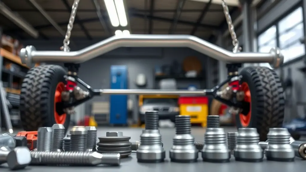
Sway bar bolt-pattern mismatches stem from chassis design, suspension geometry, and brake-assembly constraints, so expect variability in bolt-circle (PCD), thread pitch, and shoulder lengths. Typical fixes involve adapters, bushings, or redesigned mounting plates, with costs anchored to fasteners, spacers, and potential new brackets. Plan for lead times by item, plus diagnostic and test-fit labor to confirm clearance and binding. If you keep scrolling, you’ll uncover actionable timing and cost ranges, plus practical recovery options.
What Drives Sway Bar Bolt Pattern Mismatches
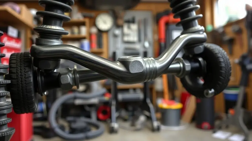
Bolt-pattern mismatches on sway bars arise from differences in vehicle design and aftermarket interchangeability. You’ll see variability rooted in chassis architecture, suspension geometry, and brake-assembly constraints that define hole spacing, stud count, and diameter. Sway bar design choices—tube diameter, end-link interface, and bushing geometry—drive compatibility with factory cams and mounts, shaping which aftermarket options fit without adapters. Installation challenges are real: you must verify cross-vehicle bolt-circle, thread pitch, and shoulder lengths, then assess mounting bracket compatibility and clearance with exhausts, steering linkages, and subframes. Mismatches aren’t just a bolt size issue; they reflect how a bar integrates with a specific vehicle’s load paths and sway characteristics. Expect potential spring-rate implications if a bar’s geometry alters leverage. Before committing, map the intended upgrade to your chassis, confirm hole alignment, and anticipate rework or adapters. Precision matching reduces fitment risk and preserves intended handling behavior.
Understanding Common Bolt Pattern Standards
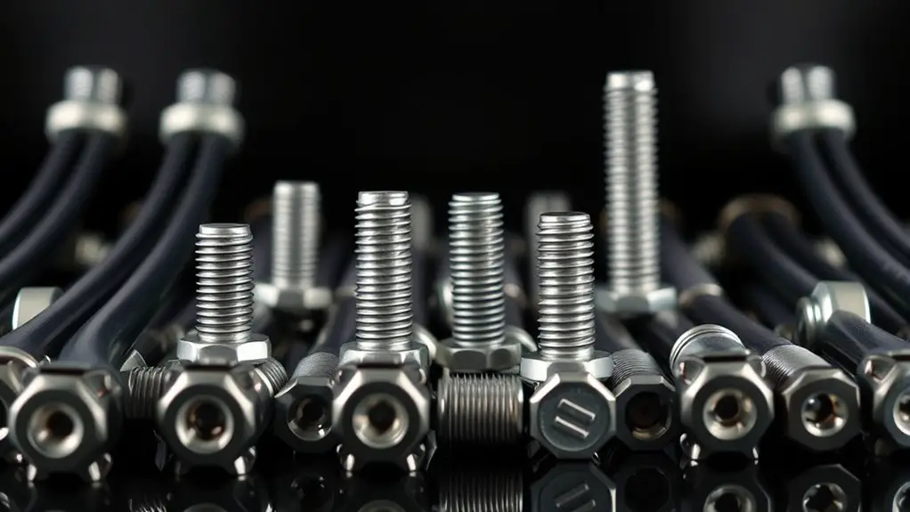
Bolt pattern standards define hole count, circle diameter, and center-to-center spacing you’ll encounter with sway bar mounting. You’ll need to align bolt patterns across mounting hardware, vehicle applications, and aftermarket components to guarantee proper fit and load transfer. Expect common measurement formats to appear in spec sheets, including PCD (mm or inches), bolt diameter, and thread pitch, so you can verify compatibility quickly.
Bolt Pattern Standards
Understanding bolt pattern standards is essential for ensuring wheel compatibility across vehicles and aftermarket parts. You assess bolt circle diameter, bolt count, and hub offset as core metrics, then map them to compatible sway bar specifications. You’ll encounter bolt pattern variations that reflect manufacturing eras, regional practices, and vehicle classes, so you compare each target wheel’s pattern against your existing sway bar mounting geometry. Precision matters: misaligned patterns yield misfit, unsafe loading, or accessory interference. Document each pattern family, noting standard spacings, thread sizes, and center bore requirements, then translate those findings into actionable fit checks during procurement. This approach supports freedom to mix and match within verified limits, while avoiding unnecessary fabrication delays. Conclude with a concise compatibility matrix to guide install decisions and future swaps.
Sway Bar Mounting
Sway bar mounting relies on matching mounting geometries to the vehicle’s suspension and chassis fixtures, so you’ll assess common bolt pattern standards to guarantee correct linkage attachment. You’ll align sway bar types with the knuckle, control arm, or chassis mounts, verifying hole spacing, thread engagement, and fastener class. Precision matters: choose compatible installation tools that fit your torque specs and clearance. Document孔 patterns and any adapters early, then prepare the mounting surface by cleaning, deburring, and verifying flatness. Select appropriate fasteners and washers, ensuring corrosion resistance and correct grip. During fitment, check for binding, contact with stabilizer bushings, and sufficient articulation range under load. This disciplined approach minimizes rework and supports reliable performance, accommodating freedom of choice within strict engineering limits.
Common Measurement Formats
Common bolt-pattern formats are defined by diameter, pitch, and bolt circle diameter (BCD), plus the number of holes. You’ll translate specs into actionable tolerances, then compare measurement formats for consistency. Understanding measurement formats helps you assess measurement accuracy and identify outliers via standard deviations, ensuring repeatable fits across suppliers. The goal is to align calipers, gauges, and CAD tolerances with practical outcomes, not abstract math. Use standardized formats to reduce misinterpretation when documenting bolt patterns for sway bars and mounts. Below is a concise reference table you can apply directly in field notes.
| Diameter (mm) | Pitch (mm) | BCD (mm) |
|---|---|---|
| 12.0 ±0.05 | 1.5 ±0.02 | 60.0 ±0.10 |
| 14.0 ±0.05 | 1.75 ±0.02 | 68.0 ±0.10 |
| 16.0 ±0.05 | 2.0 ±0.02 | 72.0 ±0.10 |
Typical Sway Bar Compatibility Scenarios
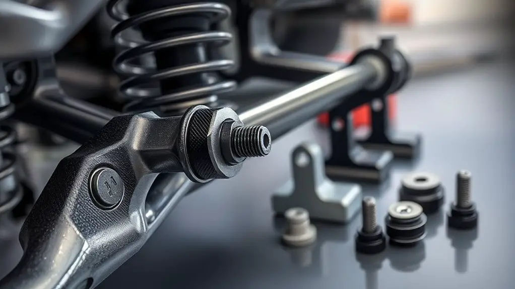
You’ll start by checking bolt pattern basics to confirm a match or identify a mismatch early. In typical scenarios, you’ll compare spoke wheel and sway bar mounting patterns, noting sleeve sizes, bushing types, and leverage geometry that affect compatibility. This sets up practical decisions for adapters, spacers, or modified links when standard patterns don’t align.
Bolt Pattern Mismatch Basics
A bolt pattern mismatch occurs when the mounting holes on a sway bar’s bracket don’t align with the vehicle’s hub or control arm pattern. In this topic, you’ll learn the basics of how bolt pattern compatibility governs fit, alignment, and load transfer. You’ll compare common configurations, recognize standard counts, and identify nonmatching diameters or spacing that create interference or unsafe mounting. Expect precise criteria: center-to-center spacing, bolt diameter, thread pitch, and stud count. You’ll assess sway bar differences across generations, trim levels, and aftermarket options without conflating vehicles. This knowledge supports practical decisions about compatibility testing, part selection, and installation sequencing. Stay focused on measurable tolerances, documentation, and reproducible checks to guarantee consistent performance and predictable handling.
Common Compatibility Scenarios
Sway bar compatibility presents a set of typical scenarios based on mounting configuration, control arm geometry, and hub spacing. You’ll map sway bar types to chassis constraints, then assess compatibility factors that drive fitment and performance. Understanding these scenarios helps you anticipate conflicts early, reducing rework and costs. Each case highlights a practical decision point, from bolt pattern alignment to lever arm clearance and end-link articulation.
- Mounting position and bar diameter dictate interference risk and stiffness outcomes
- Control arm geometry defines lever ratio, affecting roll stiffness and balance
- Hub spacing and mounting studs drive compatibility factoring into adaptors or new links
- Material and coating compatibility influence longevity and maintenance cadence
Apply these factors with discipline to optimize fit, ride quality, and overall project efficiency.
Quick Cost Assessments for Mismatch Fixes
When evaluating quick costs for mismatch fixes, start with a clear scope of the required corrective action and the materials involved, then translate that scope into unit costs and time estimates. You’ll target the minimal viable change set that resolves bolt-pattern mismatches without overengineering. Focus on direct components: fasteners, bushings, spacers, and any adapter plates, plus short labor tasks for verification. Translate parts list into cost analysis figures: unit price, supplier lead times, and expected scrap or rework. Then convert tasks into labor hours at your standard shop rate, accounting for diagnostic checks and test fitting. Prioritize fixes that restore compatibility with existing sway bar geometry while preserving torque specs and material integrity. Document assumptions and contingencies so stakeholders grasp risk and margin. Deliver a concise, actionable snapshot: cost analysis and mismatch solutions expressed as totals with confidence intervals, ready for decision, procurement, and schedule alignment.
Time Estimates for Part Sourcing and Installation
Estimating sourcing and installation times begins with cataloging lead times for each required part—fasteners, bushings, spacers, adapters, and any special brackets—then sequencing the tasks to minimize downtime.
You’ll map installation duration by item groups, flagging critical path items, and aligning supplier windows with your workshop schedule. Sourcing challenges crop up when vendors stock is limited, cross-compatibility gaps exist, or custom parts are needed, so you plan contingencies rather than surprises. Precision here saves you rework later.
- Lead-time transparency reduces guesswork and accelerates decisions
- Clear BOM links to installation duration keeps schedules tight
- Contingency buffers manage supplier variability without panic
- Explicit sequencing minimizes machine idle time and tooling changes
The result is a predictable cadence you can trust, enabling safe progress without compromising performance. Your upgrade remains efficient, deliberate, and aligned with your freedom to pursue uninterrupted driving joy.
Strategies to Avoid Delays During Upgrades
To avoid delays during upgrades, prioritize upfront risk assessment and tight change-control with your sourcing and install teams. You’ll map vendor lead times, material tolerances, and assembly constraints before you commit to a path, reducing late-stage rework. adopt a formal upgrade planning process that reserves buffer for critical steps and clearly assigns owners for decisions, sign-offs, and change requests. Streamline procurement by aligning preferred suppliers with exact bolt patterns, coatings, and fastener grades, then lock in availability windows and shipping methods to prevent shortages. During installation, codify sequence, torque specs, and fixture alignment to minimize rework from misfits or misloads. Use short, precise checklists that feed into your installation efficiency metrics, and require conformance before progressing. Maintain transparent dashboards so teams anticipate dependencies, flag risks, and reallocate resources quickly. This disciplined approach sustains momentum, reduces idle time, and supports predictable timelines without sacrificing safety or quality.
Practical Repair and Adaptation Options
Practical repair and adaptation options focus on keeping systems operational with minimal downtime while preserving safety and integrity. You’ll apply targeted sway bar adaptations and proven repair techniques to restore function without overhauling the entire suspension. Prioritize compatibility, material integrity, and load paths, then validate with quick checks to guarantee continued alignment and balance. Preparedness includes documenting part sources, torque specs, and approved fasteners to sustain long-term reliability.
Practical sway-bar fixes preserve safety with minimal downtime and clear, testable steps.
- Swiftly assess bolt pattern mismatches and select compatible bushings and end links to restore load transfer
- Implement conservative shim options or bracket modifications that preserve geometry without compromising safety
- Use verified repair techniques that maintain fatigue resistance and maintainable serviceability
- Validate post-repair performance with practical road testing and straightforward inspection criteria
These steps emphasize minimal downtime, safety, and predictable outcomes, empowering you to maintain control while pursuing freedom in your repair workflow.
Case Studies: Real-World Mismatch Fixes and Timelines
Case studies reveal how real-world mismatches are identified, prioritized, and resolved on tight timelines, demonstrating practical approaches that balance safety, performance, and downtime. You’ll see how teams map failure modes, quantify risk, and select mismatch solutions that preserve essential bolt pattern integrity while minimizing rework. Real world examples show rapid triage, targeted part substitutions, and on-vehicle validation to confirm clearance, load paths, and durability. You’ll learn to align engineering judgment with supplier data, factory tolerances, and field feedback, creating actionable roadmaps that avoid overengineering. The emphasis is on reproducible steps, not guesswork, so you can implement fixes with predictable outcomes and documented timelines. Below, a quick reference captures common tradeoffs, enabling you to communicate decisions clearly to stakeholders.
| Item | Risk/Impact | Resolution Time |
|---|---|---|
| Case A | High misfit risk | 24–48 h |
| Case B | Moderate clearance issue | 8–16 h |
| Case C | Durable alternative | 72 h |
| Case D | Hidden interference | 16–40 h |
| Case E | Material mismatch | 48–96 h |
Frequently Asked Questions
How Do Aftermarket Hubs Affect Sway Bar Bolt Patterns?
Installing aftermarket hubs can alter sway bar bolt patterns, so you’ll often see mismatches. You’ll need adapters or redesigned mounts to preserve sway bar compatibility and maintain safe suspension geometry. Check hub stud spacing, bolt-hole alignment, and fastener class. If you don’t adjust, you’ll risk binding or ineffective sway control. In practice, verify with your vehicle’s service specs, then confirm with the sway bar supplier that the chosen hubs and bar share compatible bolt patterns.
Can OEM Paint Mismatch Hide Bolt Pattern Inconsistencies?
OEM inconsistencies can’t hide bolt pattern issues, no matter the paint. You’ll want to verify pattern alignment with a caliper and cross-check against OEM specs; paint just masks wear or misalignment rather than correcting it. If patterns differ, suspect hub or sway-bar mounting deviations. In practice, inspect paint durability around fasteners to gauge coating integrity, not to validate fit. Rely on precise measurements and documented tolerances for reliable, freedom-driven maintenance results.
Are There Universal Sway Bar Fixes That Fit All Patterns?
No, there aren’t universal sway bar fixes that fit all patterns. You’ll encounter compatibility gaps, so you’ll rely on sway bar adapters or brand-specific kits. You’ll assess bolt pattern, diameter, and end-link style, then select adapters that preserve geometry and load paths. You’ll prioritize safety and precision, documenting tolerances. You’ll avoid pretend universality, embracing targeted, practical solutions that deliver real, measurable improvements for your setup.
Do Weight Ratings Influence Bolt Pattern Compatibility Decisions?
Weight ratings do influence bolt pattern compatibility decisions. You should evaluate weight capacity alongside compatibility factors to guarantee safe, effective sway-bar mounting. If the chosen setup exceeds the rated load or alters stress distribution, you’ll compromise handling and component life. Compare manufacturer specs, consider dynamic loads, and verify that mounting patterns align within tolerances. You’ll benefit from conservative selections and thorough testing to maintain performance while preserving freedom in your configuration choices.
What Safety Risks Come From Forced Adapter Solutions?
One interesting stat: nearly 40% of forced adapter setups experience some form of failure within the first 90 days. You should know that forced adapters raise installation hazards and can cause adapter failures, leaking into control, steering, and suspension performance. You’re trading safety for expediency, so verify load ratings, align bolt patterns, and inspect every fastener. If anything looks off, stop. Regular torque checks and secure mounting reduce risk and protect you on the road.

