Electrical Troubleshooting Flowchart for Faulty ECU Connections
When troubleshooting faulty ECU connections, start by understanding the ECU’s role and look for common symptoms like irregular engine performance or warning lights. You’ll need essential diagnostic tools such as a multimeter and an oscilloscope. Begin with an initial inspection of electrical connections and use a systematic flowchart approach to test power and ground circuits. Analyzing sensor inputs and verifying communication with diagnostic tools will help pinpoint issues. Continue to explore detailed steps for effective troubleshooting.
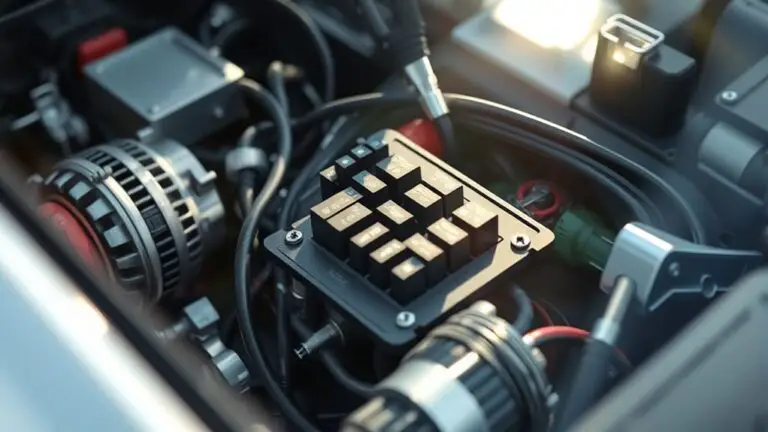
Understanding the Role of the ECU
Understanding the role of the Engine Control Unit (ECU) is essential for effective electrical troubleshooting, as this component acts as the brain of the vehicle’s engine management system. The ECU functionality overview indicates its responsibility for processing data from various sensors, adjusting engine parameters, and ensuring peak performance. It continuously interacts with critical components like the fuel injectors, ignition system, and throttle control, enabling seamless communication across the vehicle’s network.
When you grasp how ECU component interaction influences engine behavior, you reveal the potential for precise diagnostics. This knowledge empowers you to identify anomalies in the system, ensuring that you can address electrical issues efficiently. By analyzing input signals and their corresponding outputs, you can trace faults that may hinder performance. Understanding these interactions not only enhances your troubleshooting skills but also brings you one step closer to mastering the intricacies of automotive technology, providing you with the freedom to navigate repairs confidently.
Common Symptoms of Faulty ECU Connections
Several common symptoms can indicate faulty ECU connections, and recognizing them promptly is essential for effective troubleshooting. You might notice irregular engine performance, such as stalling or difficulty starting, which often suggests ECU failures directly related to poor connection integrity. Diagnostic trouble codes (DTCs) may appear inconsistently or not at all, indicating a communication breakdown between the ECU and other components. Additionally, warning lights on the dashboard may illuminate unexpectedly, signaling potential malfunctions. You could experience erratic behavior of vehicle systems, such as the transmission or fuel management, which further points to compromised connections. Finally, intermittent electrical issues, such as flickering lights or malfunctioning sensors, can also stem from faulty ECU connections. By being aware of these symptoms, you can streamline your troubleshooting process, ensuring you address the root cause effectively and restore your vehicle’s peak performance.
Tools and Equipment Needed for Troubleshooting
To effectively troubleshoot electrical issues, you need specific diagnostic tools tailored for accurate readings. Connection testing equipment is vital for verifying circuit integrity, while proper safety gear guarantees your protection during the process. Understanding these essentials will enhance your troubleshooting efficiency and safety.
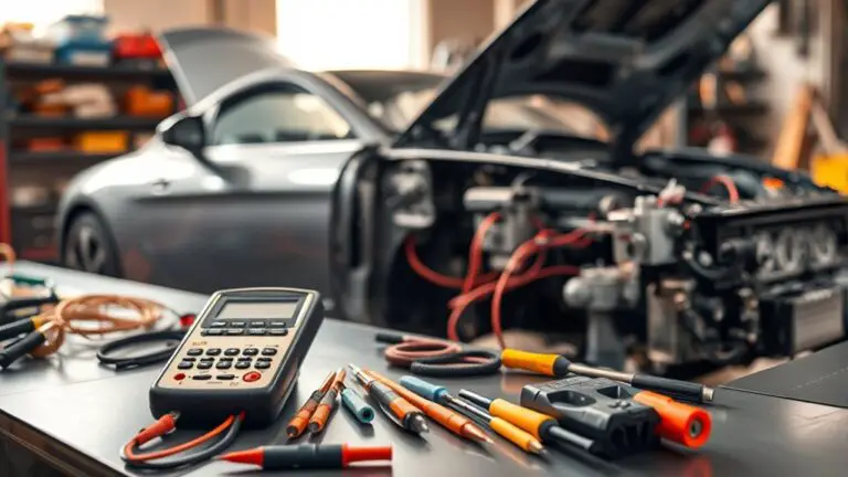
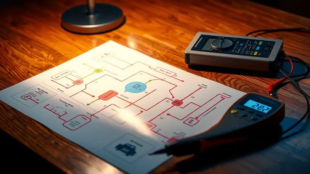
Essential Diagnostic Tools
When tackling electrical issues, having the right diagnostic tools at your disposal is crucial for an efficient and effective troubleshooting process. Start with a multimeter, which allows you to measure voltage, current, and resistance, giving you insights into circuit health. An oscilloscope can be invaluable for visualizing waveforms, helping you identify irregularities in signal patterns. Don’t overlook a basic automotive scan tool; it retrieves diagnostic trouble codes and offers real-time data from the ECU. Having a wiring diagram handy guarantees you understand circuit layouts, enabling more effective troubleshooting techniques. Finally, consider investing in a good quality test light to quickly check for power and ground issues. Equipping yourself with these essential diagnostic tools sets the foundation for successful troubleshooting.
Connection Testing Equipment
Connection testing equipment is essential for diagnosing electrical issues effectively. You’ll need a multimeter to measure voltage, current, and resistance, ensuring you assess connection quality accurately. An oscilloscope can help visualize signal waveforms, allowing you to identify irregularities in data transmission. Don’t overlook a circuit tester; it’s critical for verifying continuity in wiring. Additionally, a wire harness tester is invaluable for checking connectors and pin integrity. Remember, equipment calibration is fundamental for reliable results; regularly calibrate your tools to maintain accuracy. Using these tools will empower you to tackle electrical faults with confidence, ensuring you maintain high standards of connection quality in your troubleshooting efforts.
Safety Gear Requirements
Electrical safety gear is essential for anyone troubleshooting circuits and systems. To protect yourself, you need the right personal protective equipment (PPE). Start with insulated gloves to prevent electric shock, ensuring they meet electrical safety protocols. Safety goggles are crucial for eye protection against sparks or debris. A hard hat can be necessary in environments where overhead hazards exist. Non-conductive footwear will further shield you from electrical hazards on the ground. Additionally, consider using a voltage tester to check for live circuits before touching any components. Following these precautions not only safeguards your well-being but also enhances your troubleshooting effectiveness. By adhering to established safety protocols, you maintain freedom in your work while minimizing risks associated with electrical systems.
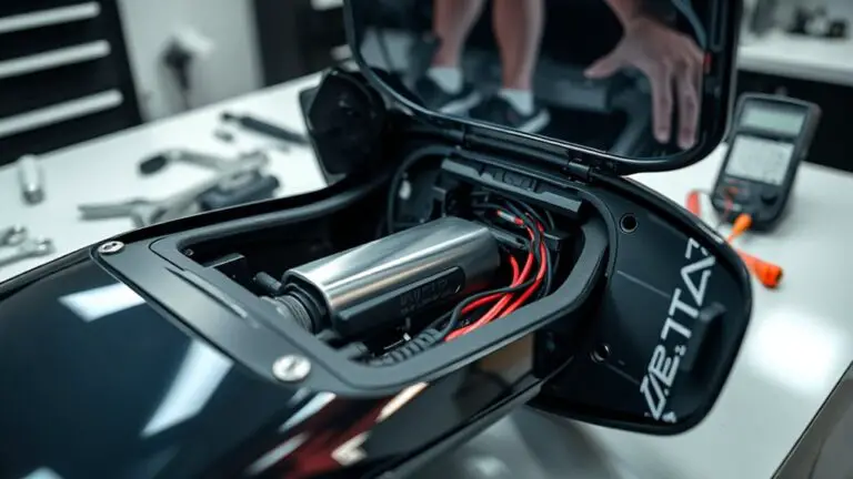
Initial Inspection of Electrical Connections
Before diving into complex troubleshooting, it’s essential to conduct a thorough initial inspection of electrical connections. Start with an initial connection assessment, focusing on both the condition of the connectors and the integrity of the wiring. Utilize visual inspection techniques to identify any signs of wear, corrosion, or physical damage. Pay close attention to loose connections, frayed wires, or burnt terminals, as these can greatly impact performance.
Make sure to inspect the pins within connectors for proper alignment and cleanliness. A simple cleaning can sometimes resolve intermittent issues. Check for any moisture ingress, as this can lead to short circuits or erratic behavior. If you notice any anomalies during your inspection, document them for further analysis. This foundational step sets the stage for effective troubleshooting, ensuring you address the most obvious issues before moving on to more complex diagnostics.
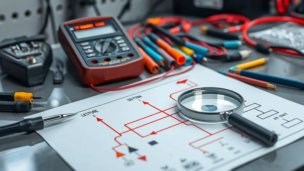
Using the Flowchart: Step-by-Step Guide
As you navigate the electrical troubleshooting flowchart, it’s essential to follow the steps methodically to pinpoint issues effectively. Pay attention to common ECU problems that may arise, as they often indicate underlying faults. Your ability to interpret the flowchart accurately will enhance your troubleshooting efficiency and accuracy.
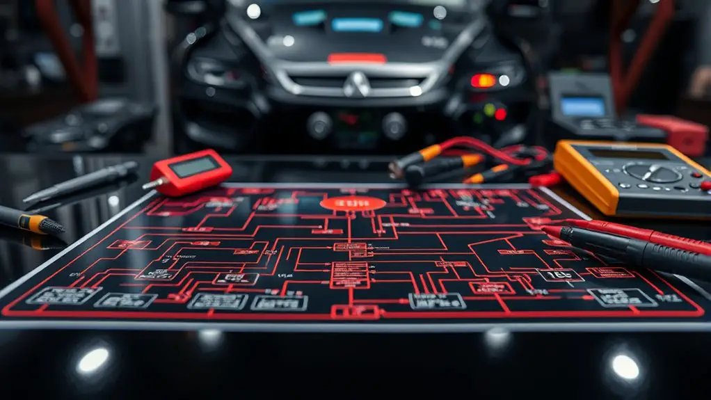
Flowchart Navigation Tips
How can you effectively navigate the electrical troubleshooting flowchart? Start by familiarizing yourself with the flowchart symbols; each represents a specific action or decision point. As you move through the flowchart, follow the arrows to guarantee you’re adhering to the logical flow of troubleshooting strategies. When you encounter a decision point, carefully evaluate the situation based on the symptoms reported. Make certain to document your findings at each step, as this helps maintain clarity and provides context for any subsequent troubleshooting. If you’re uncertain, don’t hesitate to backtrack to previous steps to reassess. Remember, thoroughness is key; rushed navigation can lead to overlooked issues, complicating the troubleshooting process. Stay methodical, and you’ll find success.
Common ECU Issues
One common issue with Engine Control Units (ECUs) is communication failure, which can greatly impact vehicle performance. This often stems from various ECU failure modes, including software glitches or hardware malfunctions. It’s important to scrutinize wiring harness vulnerabilities, as damaged or corroded connections can disrupt signals between the ECU and other components. When using the flowchart, start by verifying power supply and ground connections, then check for continuity in the wiring harness. If you identify faults, addressing these vulnerabilities is vital for restoring functionality. Keep in mind that intermittent issues may require further investigation, so don’t hesitate to reevaluate connections and harness integrity throughout your troubleshooting process. Your vehicle’s best performance depends on it.
Identifying Wiring Issues and Shorts
Identifying wiring issues and shorts is a critical step in electrical troubleshooting, often requiring a systematic approach. First, you’ll want to assess the wiring integrity by visually inspecting the harness for damage, fraying, or corrosion. Pay close attention to connectors and junction points; these are common culprits for shorts. Use a multimeter to check for continuity and resistance, which can reveal unexpected connections that may indicate a short circuit.
Next, isolate circuits by disconnecting components to narrow down the problem area. If a short is suspected, carefully trace the wiring back to its source, looking for any signs of contact with conductive surfaces or other wires. Document your findings and adjustments, maintaining a clear record of each step. By methodically identifying and resolving wiring issues, you’ll enhance system reliability and prevent future faults.
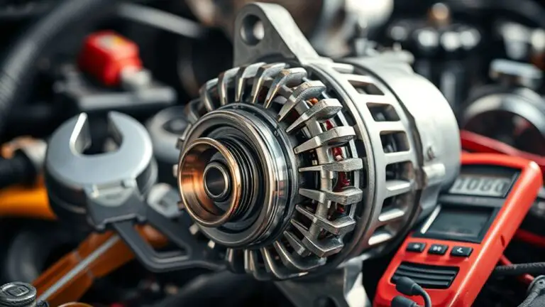
Testing ECU Power and Ground Circuits
Testing ECU power and ground circuits is essential for diagnosing electrical issues within a vehicle’s system. Proper ECU power testing and ground circuit verification guarantee that your vehicle’s electronic control unit receives the necessary voltage and is properly grounded. Here’s how to approach the testing:
- Check Voltage Supply: Use a multimeter to measure the voltage at the ECU connector. You should see the expected voltage levels.
- Inspect Ground Connections: Verify that all ground connections are secure and free from corrosion. A poor ground can lead to erratic ECU behavior.
- Look for Shorts and Opens: Check for continuity in the power and ground circuits. An open circuit or short can disrupt the ECU’s operation.
Analyzing Sensor Inputs and Outputs
When analyzing sensor inputs and outputs, you need to validate the signals being received to guarantee they’re accurate and reliable. Employing effective input validation techniques is essential for identifying potential issues early in the troubleshooting process. Additionally, understanding output signal interpretation methods will enable you to diagnose system behavior and make informed decisions.
Sensor Input Validation Techniques
As you explore sensor input validation techniques, it becomes essential to confirm that the data received from sensors accurately reflects the physical parameters they are meant to measure. Implementing robust validation processes can greatly enhance data reliability. Consider these key strategies:
- Sensor Calibration Methods: Regularly calibrate sensors to ensure they provide accurate readings based on known reference points.
- Data Accuracy Checks: Perform consistency checks against historical data or expected ranges to identify anomalies or outliers.
- Redundancy Measures: Utilize multiple sensors for critical measurements to verify data integrity through cross-validation.
Output Signal Interpretation Methods
Understanding output signal interpretation methods is vital for effectively analyzing sensor inputs and their corresponding outputs. By focusing on output signal analysis, you can guarantee signal integrity and identify potential issues.
Here’s a simple table to guide you:
| Sensor Type | Expected Output | Common Issues |
|---|---|---|
| Temperature | Voltage level | Noise interference |
| Pressure | Frequency pulse | Signal degradation |
| Position | Analog signal | Voltage drop |
Evaluating these signals helps you pinpoint discrepancies. By comparing expected outputs to actual readings, you can take corrective actions to maintain system performance. Always keep signal integrity in mind, as it’s essential for accurate analysis and reliable operation of your ECU.
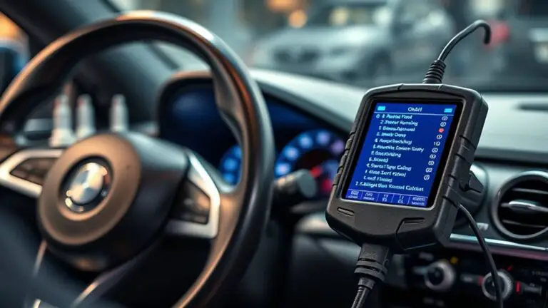
Verifying Communication With Diagnostic Tools
How do you guarantee that your diagnostic tools are effectively communicating with the electrical system? Start by checking the compatibility of your tools with the specific ECU’s diagnostic protocols. Ascertain that you’re using the correct settings and parameters to minimize communication errors. Here’s a quick checklist:
- Confirm tool readiness: Make sure your diagnostic tool is powered and up to date.
- Establish a solid connection: Verify that all connectors are secure and free from corrosion.
- Run a communication test: Use the tool’s built-in functions to check for error codes or response times.
Final Steps and Best Practices for Resolution
Once you’ve confirmed that your diagnostic tools are effectively communicating with the electrical system, it’s time to focus on resolution. Implement targeted troubleshooting strategies to identify and isolate the root cause of the fault. Begin by cross-referencing error codes with manufacturer specifications to narrow down potential issues.
Utilize resolution techniques such as re-seating connectors, repairing damaged wiring, or replacing faulty components. Always guarantee that you’re adhering to proper safety protocols during this process to maintain the integrity of both the system and your well-being.
Once repairs are made, run a thorough diagnostic check to confirm that all systems are functioning correctly. Additionally, document your findings and actions taken for future reference. This practice not only helps in maintaining clarity but also aids in quicker diagnostics should the issue arise again. By employing these strategies, you’ll enhance your troubleshooting efficiency and guarantee a robust resolution.
Frequently Asked Questions
What Are Common Causes of ECU Connection Failures?
ECU connection failures can feel as frustrating as a locked door when you need to get inside. Common causes include issues with the wiring harness, where wear and tear might lead to broken wires or shorts. Connector corrosion is another culprit, often due to moisture exposure, which disrupts the electrical flow. To guarantee reliability, regularly inspect these components, keeping your vehicle’s brain functioning smoothly and giving you the freedom to drive without worries.
How Can I Prevent Future ECU Connection Issues?
To prevent future ECU connection issues, prioritize preventive maintenance and conduct regular inspections of your vehicle’s electrical systems. Check for corrosion, loose connections, and damaged wiring. Keeping connectors clean and secure can greatly reduce the risk of failures. Additionally, staying informed about any software updates or recalls can help maintain peak ECU performance. Being proactive in these areas will guarantee a reliable driving experience and minimize unexpected problems down the road.
Are There Specific Brands Known for ECU Connection Problems?
Think of your vehicle’s ECU like the brain in a complex machine; if it’s not wired right, problems arise. Certain brands, like Bosch, have been known for failures, often leading to connection issues. Similarly, some Ford models have reported ECU-related problems. If you’re seeking reliability and freedom from constant repairs, it’s wise to research specific models and their histories before making a purchase, ensuring you avoid these troublesome connections.
Can ECU Faults Lead to Engine Performance Issues?
Yes, ECU faults can definitely lead to engine performance issues. When the ECU misinterprets data due to faulty connections, you might experience poor fuel efficiency, sluggish acceleration, or even stalling. Effective ECU diagnostics are essential to pinpoint these faults. By analyzing the signals sent to various components, you can identify discrepancies that affect overall engine function. Addressing these issues promptly can restore your engine’s performance and guarantee smoother operation.
Is Professional Help Recommended for ECU Troubleshooting?
Yes, professional help is recommended for ECU troubleshooting. Imagine your car’s engine misfiring; it could be a faulty ECU. Technicians use advanced diagnostic tools and sensor testing to pinpoint the issue accurately. They can interpret error codes and check connections that you might overlook. While DIY methods may work for some, the complexity of modern ECUs often requires expert knowledge to guarantee a thorough and effective resolution. Trusting professionals can save you time and frustration.