Step-By-Step: Fixing a Faulty Wheel Speed Sensors That Triggers ABS Light on
To fix a faulty wheel speed sensor that triggers the ABS light, start by diagnosing fault codes and verifying live data for each wheel to locate the implicated sensor. Inspect wiring, connectors, and harnesses for damage or corrosion, then test coil resistance and sensor output with proper equipment. Replace or repair the faulty sensor, reseat connectors, and apply dielectric grease where appropriate. Recheck all codes, then perform a controlled road test to confirm proper ABS operation and sensor data sync. You’ll uncover deeper steps as you continue.
Diagnosing ABS Sensor Faults and Symptoms
When diagnosing ABS sensor faults, start by confirming the fault code(s) and reviewing live data from the wheel speed sensors. You’ll map codes to specific wheels and scan for intermittent signals, dips in voltage, or irregular PWM patterns. Observe wheel speed readings during steady rotation and boot-up; inconsistent values suggest sensor or harness issues, not just a controller fault. Note how fast you scroll through sensor data to detect sporadic drops or spikes that align with a warning interval. Compare data across all four corners to identify asymmetry, which points to a likely sensor malfunction causes. Look for known failure modes like open circuits, shorted wires, or degraded connectors. ABS warning indicators should correlate with abnormal readings, confirming the fault source. Document findings clearly, correlating codes with live data. This methodical approach keeps you focused on measurable symptoms, enabling precise diagnosis and targeted repairs.
Safety Precautions Before Starting Work
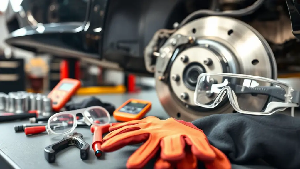
Before you begin, gather the required PPE and tools, and confirm the vehicle is securely supported. You’ll approach this work with discipline and clear steps, minimizing risk to yourself and others. Wear safety gear that fits, and verify you have a fire extinguisher and a first-aid kit within reach. Establish a safe workspace: disconnect the battery if advised by the manual, allow components to cool, and keep a clean, organized bench. Review emergency procedures in case of fluid spills or injury. Keep hands dry and avoid loose garments. Maintain lighting, ventilate if indoors, and avoid distractions. If something feels uncertain, pause and reassess.
| Safety gear | Tools and setup |
|---|---|
| Eye protection, gloves, closed shoes | Torque wrench, screwdrivers, jack stands, rags, container for fluids |
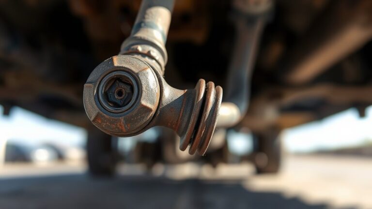
Locating Wheel Speed Sensors on Your Vehicle
Locating wheel speed sensors on your vehicle requires a systematic approach to identify each sensor and its wiring without causing damage. You’ll scan the brake rotors, hubs, and gears for discreet, often metal-encased components that connect to the wiring harness. Expect two sensors per axle, with one on each wheel, positioned near the rotor or tone ring. The sensor locations may vary by make, model, and ABS system, so refer to the service manual for exact geometry. Look for small connectors, short harness runs, and protective boots that seal against moisture. Verify wiring routes follow frame members and avoid hot exhaust or moving components. Distinguish wheel speed sensors from other pickups by their positioning and connector shape. Confirm grounding points are solid and corrosion-free before testing. A precise visual map now saves you confusion later.
- Visual inspection of each wheel area
- Connector and harness routing checks
- Rotor/tone ring proximity assessment
- Grounding and corrosion scan
- Cross-reference with vehicle manual
Tools and Equipment You’ll Need
To diagnose and fix a faulty wheel speed sensor, assemble a focused set of tools and equipment that cover measurement, access, and electrical testing. You’ll want a digital multimeter with min/max, an automotive scan tool, and a simple ohm/continuity tester for quick checks. Include a small mirror, flashlight, and a magnetized pick to aid access without disturbance. For mechanical access, carry jack stands, wheel chocks, and a set of metric and Torx sockets; a pry tool or trim removal tool helps without damage. A handheld flashlight, disposable nitrile gloves, and clean rags keep the workspace tidy and safe. For sensor-specific work, obtain a spare sensor or known-good unit for reference during tests, and confirm compatibility with sensor types used on your vehicle. Ascertain you have a service manual or OEM guidance, since proper diagnostics depend on vehicle-specific wheel speed sensor behavior and wiring schematics. Wheel speed measurement and sensor types guide your method.
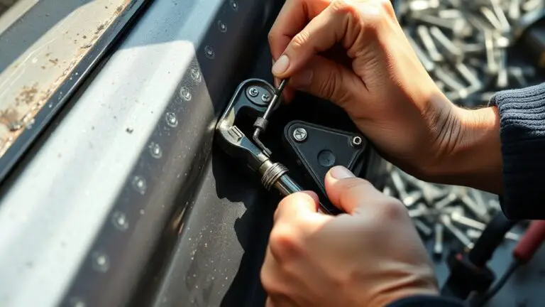
Inspecting Wiring, Connectors, and Harnesses
With the wiring harnesses in mind, you’ll inspect the pathways that carry power and signals to the wheel speed sensor. You approach this with a calm, precise method—no guesswork, just solid checks that prevent rework. Focus on continuity, insulation integrity, and protection from wear. You’ll document findings for reliable diagnosis and future maintenance.
- Check for damaged insulation and pinched wires near the hub and wheel well
- Inspect connectors for corrosion, bent terminals, and secure locking features
- Verify that harnesses are routed away from heat sources and moving parts
- Confirm terminal seating and pin alignment through careful connector evaluation
- Look for stress points where loom ties or zip ties have pinched or fatigued the wires
During wiring inspection, separate the sensor circuit from auxiliary harnesses to avoid cross-talk. Repair or replace compromised sections, re-seat connectors fully, and recheck all paths for dobrail integrity before you proceed to testing.
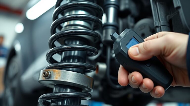
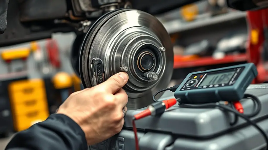
Testing Sensor Resistance and Signal Output
You’ll start with resistance testing by measuring the sensor’s coil resistance against the manufacturer’s spec, ensuring the reading is within tolerance at room temperature. Next, you’ll verify the sensor’s signal output by monitoring the electrical waveform or voltage range under simulated wheel speed, comparing it to expected levels. Use a multimeter or oscilloscope, document the values, and note any deviations that suggest a fault or needed adjustment.
Resistance Testing Basics
Resistance testing basics: before you measure, confirm the sensor’s wiring and reference ground are correct, then set your meter to the appropriate range to obtain stable readings.
- Use the proper sensor testing equipment to minimize noise and error
- Verify cold resistance with the wheel at rest for consistency
- Record baseline values and compare to OEM specifications
- Note insulation integrity and connector condition before testing
- Document any deviation and plan a targeted inspection
This approach aligns with resistance measurement techniques, ensuring repeatable results. You’ll work with deliberate test points, avoiding stray paths that skew data. Maintain clean contacts, avoid heat influence, and separate power-off steps from measurement to prevent transient errors. Fidelity in this phase supports accurate diagnosis and prepares you for subsequent signal-related checks.
Signal Output Check
To verify the sensor’s signal output, connect the appropriate test equipment and reference ground, then monitor both the steady-state resistance and the dynamic signal during rotation. You’ll judge signal interpretation by comparing peaks, troughs, and timing to expectations, ensuring output consistency under load changes and wheel speed. Document deviations and repeat at multiple speeds to confirm reliability.
| Condition | Observation |
|---|---|
| Static resistance | Within spec, no drift |
| Dynamic waveform | Clean pulses, no jitter |
| Speed ramp | Timely shifts, no lag |
| Load variation | Output stable, repeatable |
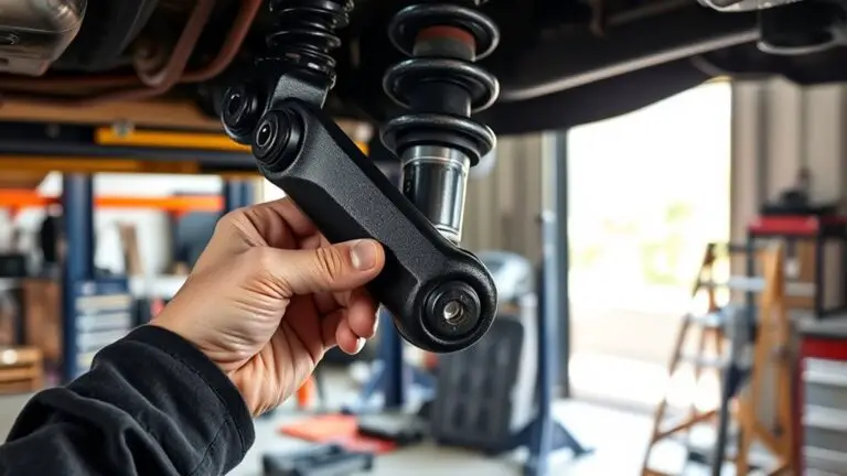
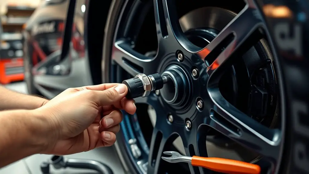
Replacing or Repairing a Faulty Wheel Speed Sensor
Replacing or repairing a faulty wheel speed sensor requires careful diagnosis and a controlled workflow. You’ll identify whether the issue is sensor failure, wiring, or connector corrosion, then decide between replacement or targeted repair. Follow precise steps to minimize risk to the ABS system and maintain vehicle safety.
Replacing a faulty wheel speed sensor requires careful diagnosis, targeted repair, and safe, precise replacement of components.
- Inspect harness connectors for corrosion, frayed wires, and proper seating.
- Verify sensor positioning and gap to the tone ring with the correct tool.
- Clean or replace sensor connectors; apply dielectric grease where appropriate.
- Swap a faulty sensor with an OEM part or test a suspect unit in a known good harness.
- Document readings, perform sensor replacement techniques, and capture fault codes for troubleshooting tips.
This approach keeps you in command, preserving freedom to work efficiently. Maintain clean work surfaces, use torque specs, and recheck system readiness after installation to guarantee reliable ABS operation.
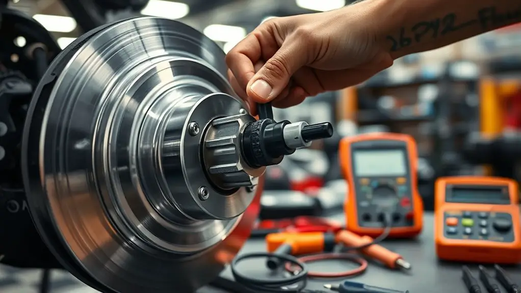
Verifying ABS System Function After Repairs
After completing the sensor repair, perform a post-repair ABS check to confirm system readiness and activation of the ABS warning light behavior. Then verify sensor function across all wheels and confirm no fault codes persist via the vehicle’s diagnostic tool, performing a system diagnostic refresh if needed. Document results clearly and proceed with road testing only after all subsystems show nominal readings.
Post-Repair ABS Check
Once the repair is complete, perform a structured post-repair ABS check to confirm system integrity before road testing. You’ll verify the ABS system readiness you just reinstated, guaranteeing no fault codes remain and that the controller communicates correctly with each wheel sensor. Focus on clean diagnostics, repeatable results, and clear pass/fail criteria during this post repair inspection.
- Confirm no pending codes and clear any that reappear after a brief scan
- Confirm proper wheel speed sensor data flow during rotation
- Validate ABS controller reports and fault history are reset
- Guarantee brake pedal feel is stable and ABS engages only on genuine slip
- Verify no abnormal ABS cycling during simulated stop or light brake test
Sensor Function Verification
Sensor Function Verification: start by confirming that each wheel speed sensor provides clean, band-limited signals within expected voltage ranges as the wheel turns, and that the ABS controller accurately samples these signals without interruption. You’ll verify that no intermittents or ground faults distort data, and that signal timing aligns with wheel position under varying load. Use diagnostic tools to observe real-time waveform shapes, amplitudes, and noise floor, ensuring consistent cadence across all channels. Perform sensor calibration checks to confirm that outputs map to actual rotational speed with minimal error, recalibrating if necessary. Confirm the ABS module recognizes each sensor’s state changes without spurious missing pulses. Document acceptance criteria, then proceed only when all channels meet specified thresholds and stability targets.
System Diagnostic Refresh
Building on the sensor-function checks, a focused System Diagnostic Refresh evaluates the ABS system’s behavior as a whole after repairs. You’ll confirm that repaired channels synchronize with the control module, and that the actuator outputs respond predictably under load. Use diagnostic tools to cross-check wheel-speed sensor data, pump operation, and modulator function, ensuring no lingering faults. The goal is a clean, repeatable system state, not just a single test pass.
- Verify consistent wheel-speed readings with no phantom deltas
- Confirm proper pump and modulator engagement during simulated braking
- Check for zero fault codes after clearing and retesting
- Measure ABS hydraulic pressure response under controlled input
- Validate stability of ABS warning light behavior across cycles
Frequently Asked Questions
Can ABS Light Come on From Causes Other Than Wheel Speed Sensors?
Yes, the ABS light can come on from causes other than wheel speed sensors. You might face sensor malfunction, but also brake system issues like low fluid, worn pads, or caliper sticking, plus electrical faults in the ABS control module or wiring. Anticipate a single fault sounding the alarm while others hide behind multiple faults. Start by scanning for codes, verify sensor data, inspect hydraulics, and check for corroded connectors before replacing components.
How Long Should a Repaired Sensor Last Before Recheck?
You should expect the repaired sensor to last multiple years under normal driving, but verify during a recheck at least every 12 months or 12,000–15,000 miles, whichever comes first. Sensor longevity depends on installation quality, wiring protection, and road conditions. Track performance expectations by noting consistent wheel speed readings and no ABS faults. If a discrepancy appears, re-test, inspect harnesses, and consider replacement rather than patching. Maintain proactive checks to sustain reliability and safety.
Will ABS Brake Bleed Be Required After Sensor Replacement?
Replacing the sensor itself usually doesn’t require a full ABS bleed, but it can depend on the system. You’ll likely not need a brake fluid bleed unless you disturbed the lines or contaminated fluid. After sensor installation, cycle the ignition, drive softly to let the ABS learn, and scan for codes. If a pressure check shows air or contamination, bleed only the affected circuit. Precision matters, but freedom means you verify with a diagnostic tool.
Do I Need Specialized Tools to Test Sensor Output?
You don’t strictly need specialized tools, but you do need proper sensor testing with diagnostic equipment. You can test output using a multimeter or scan tool to read wheel speed sensor data and consistency. Confirm you have accurate reference specs and use the diagnostic equipment to verify signal integrity and voltage ranges. If readings are off, recheck wiring, gaps, and harness routing. Precision matters, so document everything for reliable, repeatable results.
Can Aftermarket Sensors Affect ABS System Calibration?
Yes, aftermarket sensors can affect ABS calibration if they’re not compatible. You should verify sensor compatibility with your vehicle’s ECU and wheel hub geometry, and consider the quality level of aftermarket parts. Choose aftermarket quality sensors that match OEM specs, then recheck ramping and tone wheel alignment. After installation, you must recalibrate or relearn the ABS sensors per your vehicle’s procedure to maintain proper braking control and avoid false ABS activations.