Step-By-Step: Fixing a On-Board Charger Fault Safely
To fix an on-board charger fault safely, start by powering down, unplugging the charging supply, and isolating the system. Assess safety first, checking for moisture, damaged connectors, and excessive heat. Gather PPE and insulated tools, then review fault indicators against the manufacturer’s codes. Verify the input power and wiring, guarantee proper grounding, and segment the circuit to isolate the fault. Inspect gaskets, seals, and connectors, then retest with low current. More detailed steps await if you continue.
Assess Safety First: Understanding On-Board Charger Faults
Evaluating safety is the first and most critical step when an on-board charger fault is suspected. You approach the task with purpose, not haste, and you’ll map a clear path through uncertainty. Begin by identifying symptom patterns—unusual heat, intermittent charging, or fault codes—so you know what to verify. Next, confirm power-down and isolation: disconnect the vehicle, unplug the charging supply, and lockout the circuit to prevent accidental re-energizing. Adhere to safety protocols that prioritize personnel protection and equipment integrity. Assess the environment for moisture, residue, or damaged connectors, which can masquerade as faults. Document findings with objective notes and photographs to support diagnostics and future prevention. Maintain a controlled workspace, keeping knots of energy paths visible and uncontaminated. Finally, establish escalation criteria: if symptoms persist after basic checks, proceed with structured diagnostics or consult qualified technicians. Your focus remains safety-first, precise, and disciplined.
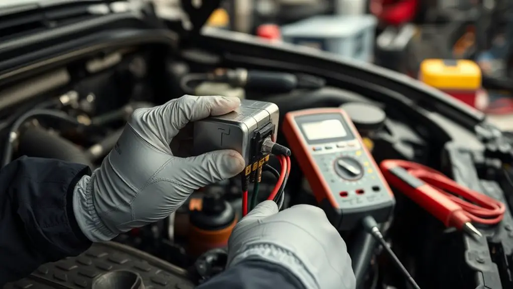
Tools and PPE You’ll Need for Safe Troubleshooting

You’ll need a clear set of tools and PPE designed for electrical diagnostics and safe handling of high-voltage systems. In this section, you’ll select equipment that enhances safety and precision, aligning with safety guidelines and your freedom to troubleshoot confidently. Choose gear that demonstrates rugged reliability and clear labeling, so you can work with focus and reduce guesswork.
- InsulatedTools: voltage-rated, non-slip grip, and clearly marked categories
- DielectricGloves: rated for the expected voltage, with outer gauntlets for protection
- SafetyShield: face and eye protection that fits over glasses and a metal-free visor
- VoltageDetectorKit: non-contact and contact-capacitance options for quick verification
Keep maintenance logs, inspect gear before use, and retire items showing wear. This approach guarantees you stay within essential equipment parameters without compromising agility or safety. Remember: your confidence grows when tools and PPE align with concrete safety guidelines and practical, precise execution.
Interpreting Fault Indicators and Diagnostic Codes

When a fault indicator lights up or a diagnostic code appears, start by confirming the symptom against the vehicle’s service documentation and your safety plan. You’ll translate the code into actionable steps, noting the exact code, the operating state, and any recent changes or events. Record time, temperature, and whether the charger was connected to a valid power source. Compare the indicator lights with the manufacturer’s fault-code table and any retrofit documentation you trust. Prioritize reproducibility: can you recreate the fault under controlled conditions, or is it intermittent? If multiple codes appear, identify the dominant fault and treat it as the primary failure mode. Keep a running list of likely causes and verify them with targeted tests. Document all findings succinctly, reserving conclusions for repair decisions. Throughout, maintain a clear focus on safety, ensuring access to emergency shutoffs and adherence to your plan. Fault codes and indicator lights guide, never replace systematic verification.
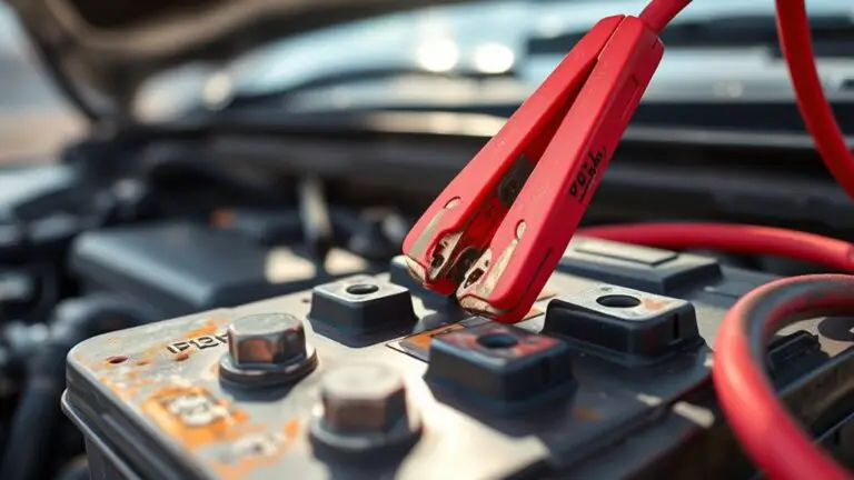
Verifying Power Supply and Inputside Wiring
Once you’ve logged the fault indicators and ruled out obvious causes, start by confirming the incoming power supply and input-side wiring are healthy before proceeding with further diagnostics.
Once fault indicators are logged, verify the incoming power and input wiring before deeper diagnostics.
- Perform a power supply check at the source and verify voltages meet spec during idle and load conditions
- Inspect input wiring for signs of damage, loose connections, corrosion, or insulation wear during a careful wiring inspection
- Verify proper grounding and shield integrity to prevent stray currents from skewing readings
- Confirm breaker or fuse ratings match the system requirements and are free of nuisance trips
Keep tools insulated, follow lockout-tagout practices, and document any anomalies you find. If readings deviate from expected values, stop and reassess before moving deeper. The goal is a clean baseline of power supply health and wiring integrity to support accurate fault isolation later. Proceed only when you’ve established stable input conditions and safe access.
Isolating the Fault: Segmenting the Charging Circuit
You’ll start by outlining fault isolation techniques to localize issues without disturbing unrelated circuits. Next, segment the power path to limit risk, verifying each section step by step with proper de-energization and safe isolation practices. This methodical approach keeps safety front and center while guiding you toward pinpointing the fault area.
Fault Isolation Techniques
Segmenting the charging circuit is a foundational step in fault isolation, because it lets you pinpoint which section is causing an issue without exposing the entire system to risk.
- Apply controlled power-downs and verify isolation boundaries before tests
- Use fault detection methods to identify abnormal readings without altering normal operation
- Document each segment’s behavior and compare against expected parameters
- Follow troubleshooting protocols to escalate only when defined thresholds are exceeded
Keep your approach precise and iterative: test, observe, and record results, then reassess. Maintain PPE, use insulated tools, and minimize live-contact exposure. Confirm connectors are clean and seated, and that shielding is intact. If an anomaly persists, isolate the suspected module and re‑confirm with a second, independent test. This disciplined method reduces risk while guiding you toward the root cause.
Segmenting Power Path
As you segment the power path, start by mapping the main supply, contactors, and high-current routes to establish clear isolation boundaries; then power down, verify each boundary, and test progressively downstream to pinpoint where faults appear. You’ll focus on power distribution logic, tracing paths from the source through fuses and breakers to the charger input. Maintain strict circuit protection discipline: confirm ratings, verify interlocks, and document each step before moving on. Isolate subsections, recheck continuity, and compare with expected norms, ensuring no hidden load remains energized. Verify that relays respond correctly under test conditions and that any faulted segment is clearly identified without upsetting neighboring channels. Finish with a concise risk assessment, ready to proceed to targeted repairs safely.
Safe Isolation Practices
When isolating the charging circuit, start by confirming the main power source is de-energized and locked out, then verify each boundary with independent testing before proceeding. You’ll implement disciplined safety protocols and clear isolation methods to prevent arc flash or backfeed. Focus on establishing a safe boundary, then isolate the fault segment without compromising other circuits. Maintain a calm, controlled sequence, documenting each step and result for traceability. Keep PPE and tools dedicated to the task, and resist rushing through checks that protect you and others. After isolation, recheck all connections and signs of energy before work continues. Remember: precision, accountability, and discipline enable freedom from risk.
- Verify shutoff boundaries with independent tests
- Lockout, tagout, then recheck
- Use dedicated, rated tools
- Document results and status continuously
Inspecting Connectors, Cables, and Seals for Damage
You should begin by checking cable integrity for any cuts, fraying, or exposed conductors, tightening or replacing damaged sections as needed. Next, inspect seals and for moisture, ensuring gaskets are intact and dry before reassembly. Finally, examine connector pins for bending, corrosion, or corrosion, and verify proper seating and secure locking before testing.
Inspecting Cable Integrity
Inspecting cable integrity starts with a careful physical check of the connectors, cables, and seals. You examine for visible cracks, cuts, and swelling, then verify that fittings are snug and free of corrosion. Move slowly, noting any signs of damage that could affect insulation or current flow. Remember cable wear and insulation integrity are critical for safe operation; don’t overlook hidden frays inside sheathing.
- Inspect connector pins for corrosion or bending
- Look along the cable length for cracks, kinks, or heat marks
- Check strain relief and attachment points for looseness
- Test seals near joints for any deformation or gaps
If you spot damage, tag the component and avoid use until replaced or repaired by a qualified technician. Prioritize safety and clarity over haste.
Seals and Moisture Check
Seals and moisture check begins with a careful examination of all entry points and joints for signs of degradation or intrusion; any gaps, deformation, or softened sealant warrant closer inspection. You’ll inspect connectors, cables, and seals for evidence of moisture intrusion and compromised seal integrity, focusing on tightness, alignment, and continuity. Look for cracks, pinching, or corroded fasteners, then document findings before proceeding. Use a clean, dry workspace and gentle handling to avoid disturbing gaskets. If you detect leakage, address it only after power is isolated. The following quick table guides your visual checks:
| Area | What to look for | Action if abnormal |
|---|---|---|
| Seals | Cracks, deformation | Replace sealant or gasket |
| Cables | Water stains, fraying | Abduct or replace affected length |
| Connectors | Condensation, stiffness | Clean and reseal, reseat properly |
Connector Pin Condition
When checking connector pin condition, start by safely isolating power and removing any covers to expose the mating surfaces. You inspect for wear, bending, masking, and any signs of pin corrosion; replace any damaged pins and reseat properly. Check connector alignment so pins mate cleanly without forcing. Look for scorched or melted areas, salt deposits, or moisture ingress. Clean with approved contact cleaner if allowed, and dry completely before reassembly. Verify seals are intact and seating is snug to prevent future corrosion. Document findings and retest the circuit with low current before full use. Maintain a proactive mindset, prioritizing safety, accessibility, and reliability.
- Inspect alignment and seating for proper engagement
- Look for pin corrosion and replace as needed
- Check seals and moisture protection
- Clean and dry contacts using approved products
Testing Components: Fuses, Relays, and Protective Devices
Testing components like fuses, relays, and protective devices is a practical, stepwise check you can do to rule out common failures in an on-board charger. You’ll verify fuse integrity with a visual inspection and continuity test, ensuring no micro-fissures or discoloration exist. Relays get a direct coil test and a contact resistance check, confirming proper actuation and clean, low-resistance paths when energised. Protective devices—surge suppressors, thermistors, and circuit breakers—warrant inspection for scorch marks, proper trip values, and correct sizing for the system’s fault current. Document readings and compare them to manufacturer specs; deviations point to fault detection techniques you can apply before more invasive work. If a component shows doubtfully high resistance or intermittent operation, consider careful component replacement strategies, using compatible parts and secure terminals. Keep the sequence logical, note outcomes, and proceed only when measurements meet defined thresholds.
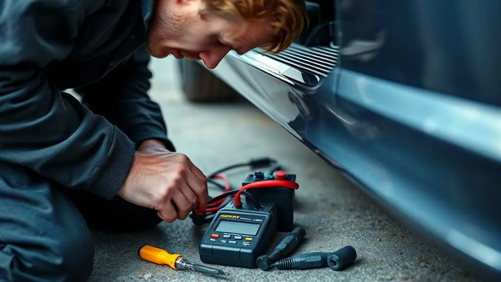
Safe Testing Procedures After Each Intervention
After each intervention, you should follow a disciplined testing routine to affirm that no new issues were introduced and the system remains safe to operate. Begin with a visual check for obvious damage, loose connections, and signs of heat or distress. Next, perform noncontact voltage readings where applicable, verifying expected potentials match the schematic. Proceed to functional tests on affected subsystems, documenting results and noting any deviation. Ascertain protective devices reset properly and that indicators reflect correct status. After each test, re-check safety interlocks and enclosure integrity before powering. Maintain a clear log to support intervention verification and traceability. If any anomaly appears, halt further testing and reassess before continuing. Prioritize repeatability, minimal disruption, and defined pass criteria to safeguard operation and future interventions. Remember, disciplined testing protects both equipment and freedom to use it confidently.
- Confirm safe testing parameters and documented results
- Verify no unintended interactions between subsystems
- Validate interlocks, indicators, and reset behavior
- Record outcomes for traceability and future reference
Post-Repair Validation and Preventive Tips
Post-repair validation is essential to confirm the charger operates safely and reliably, so you should start with a structured verification plan and clear pass criteria. You’ll document test steps, expected outcomes, and safety checks, then execute them in a controlled sequence. Begin with external inspection for loose connectors, damaged insulation, and signs of arcing. Move to functional tests using rated loads, monitoring voltage, current, temperature rise, and fault codes in real time. If anything diverges from spec, halt and isolate the fault, then re‑test after corrective action. Record results meticulously to support traceability and future maintenance. Integrate post repair maintenance into a routine: schedule checks for wiring strain, connector wear, and cooling performance. Implement preventive inspections that focus on safety interlocks, insulation integrity, and enclosure ventilation. Leave no ambiguity about pass/fail criteria, and validate that the system behaves under fault conditions as designed. End with a concise handover note for ongoing reliability.
Frequently Asked Questions
What Safety Gear Is Mandatory for On-Board Charger Work?
Safety goggles and insulated gloves are mandatory for on-board charger work. You should also wear flame-resistant clothing and non-conductive footwear, and use a face shield when sparks or splashes are possible. Keep a properly rated maintenance mat, insulated tools, and a voltage tester nearby. Before starting, de-energize, lockout/tagout, and verify absence of voltage. Follow manufacturer guidance, monitor environment for moisture, and never bypass PPE. Safety first, then you’ll work with confidence and freedom.
Can I Diagnose Faults Without Touching Live Circuits?
Yes, you can diagnose faults without touching live circuits. Start with fault diagnosis using non-contact methods and portable instrumentation. Use circuit testing on de-energized modules only, verify isolation, and follow manufacturer procedures. Keep your gloves, eye protection, and insulated tools on hand, and confirm zero voltage before any probing. Document readings carefully, then plan safe test steps. This approach lets you assess issues while preserving your safety and maintaining control over the fault diagnosis process.
How Do I Confirm a Fault Is Intermittent or Persistent?
A fault is intermittent if it appears inconsistently; a persistent fault shows up every time you reproduce the condition. Start with careful fault testing and controlled observation techniques: log timestamps, note environmental factors, run partial tests, and repeat cycles. Don’t rush conclusions—verify once more after minor changes. If it disappears, call it intermittent; if it remains, mark as persistent. Maintain safety, document findings, and trust repeatable patterns to guide repairs.
What Follow-Up Steps Ensure No Reoccurrence of Faults?
To prevent reoccurrence, you should implement preventive maintenance and schedule regular inspections after any fault. You’ll verify fault history, replace worn components, tighten connections, and update firmware if applicable. Document findings, set trigger points for checks, and train operators on early warning signs. Maintain a log for trend analysis, perform functional tests, and confirm safety interlocks. By staying proactive, you reduce risk, enhance reliability, and preserve the freedom to operate confidently.
Are There Common Mistakes That Escalate Charger Damage?
Shadows reel like tangled wires, a symbol of risk you must respect. Yes—common mistakes escalate charger damage: skipping diagnostics, using damaged cables, ignoring heat, and plugging into unsuitable power. You should perform charger maintenance with care, note fault codes, and avoid improvisation. Use diagnostic tools properly, verify grounding, and disconnect before inspection. Stay methodical, safety-conscious, and free-spirited in testing. Don’t rush; precision protects your rig and your ride.