How to Prepare Your Car and Tools Before Tackling Fault Codes Returning After Repair
Start by cleaning and inspecting all electrical connections, especially battery and fuse-block grounds, then work outward to sensors and actuators. Verify power and ground integrity with a multimeter, checking for stable voltage and low resistance on chassis and battery grounds. Set up a safe, well-lit workspace, organize tools by function, and use PPE. Calibrate and validate diagnostic tools, then map a systematic scan plan and data-logging protocol. If issues persist, you’ll uncover deeper steps you can pursue next.
Cleaning and Inspecting Electrical Connections
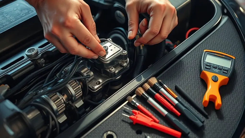
Cleaning and inspecting electrical connections is essential for reliable fault-code diagnostics. You approach this task with a clear plan: identify likely problem areas, assess terminal cleanliness, and verify secure mating. Begin at the battery and fuse-block grounds, then work outward to sensors and actuators. Look for signs of connection corrosion—green or white residue, darkened terminals, or looseness. Document any corrosion present, but don’t assume it’s the sole cause of a fault; test continuity where possible to confirm impact. As you clean, use appropriate contact cleaners that evaporate fully and won’t leave residues. After cleaning, inspect for cracking insulation or frayed wiring that could compromise signals. Apply a thin layer of dielectric grease to each connector pin and back-shell if the manufacturer allows; this helps seal moisture and slows corrosion. Re-seat connectors firmly, ensuring a crisp, audible click. Finally, recheck voltages and grounding paths to validate that nothing else was disturbed during the inspection.
Verifying Power and Ground Integrity
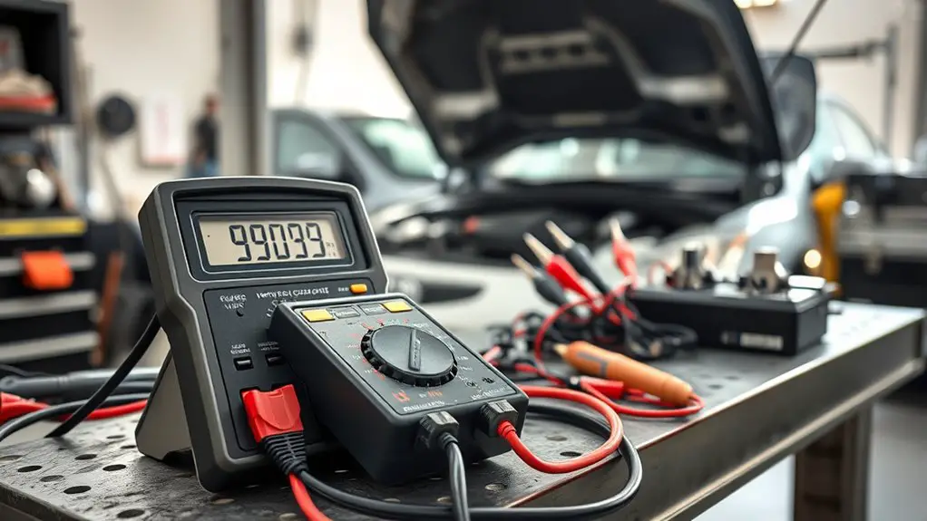
Verifying power and ground integrity requires a structured, evidence-based approach. You’ll start by confirming the battery and main fuses supply stable voltage, then test chassis and battery grounds for continuity. Any significant resistance here can masquerade as sensor faults. Use a multimeter to measure voltage drop under load, noting readings across wiring harness grounds and common returns. When power faults exist, trace paths with wiring diagrams to isolate sections without tearing apart the entire loom. Document each node’s voltage and resistance to build a clear, testable map for circuit analysis. Pay close attention to connector integrity, corrosion, and pin deformation; even small gaps create high resistance that skews ECU inputs. Establish a baseline by comparing readings to the vehicle’s service data, and repeat checks after any service. This disciplined approach minimizes false positives and supports reliable fault-code resolution.
Preparing a Safe and Organized Work Environment

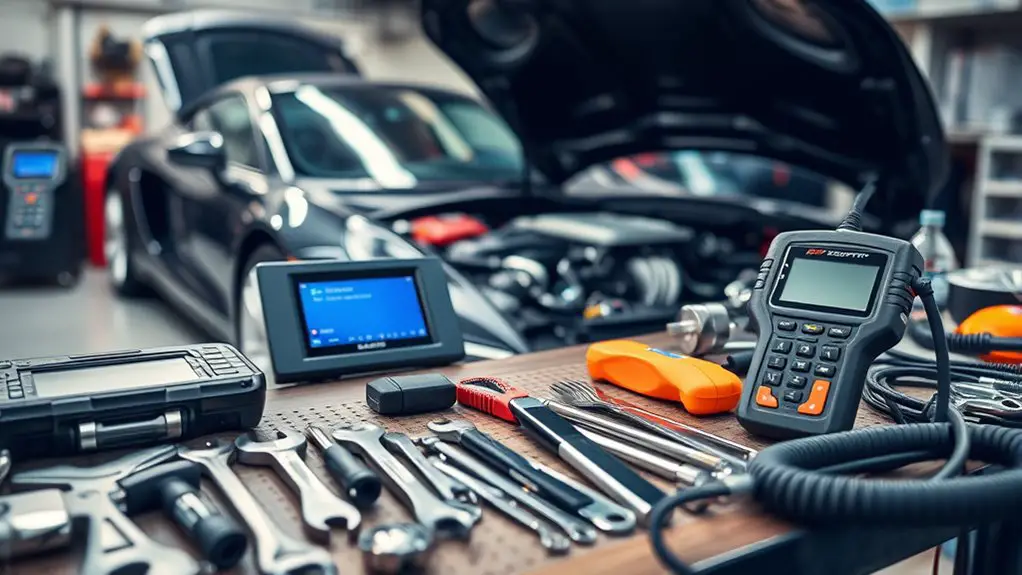
Set up your work area with a clearly defined bench, adequate lighting, and non-slip surfaces to minimize distractions and errors. Organize tools by function and frequency of use, so you can access what you need without interrupting the diagnostic flow. Establish safety protocols—PPE, battery disconnects, and proper spill control—to protect you and guarantee consistent results.
Work Area Setup
A well-organized work area is the foundation for accurate fault-code diagnosis. You set a clean, uncluttered baseline, then define zones for inspection, testing, and documentation. Begin with a deliberate workbench arrangement that prioritizes flow: clear access to tools, components, and reference manuals without cross-traffic. Establish adjacency between diagnostic panels and power sources, while isolating potential hazards from sensitive electronics. Lighting considerations are essential: even, shadow-free illumination reduces misreads and fatigue, with adjustable color temperature to discern connector wear and coating discoloration. Keep a small, labeled trash and bin for discarded packaging to prevent contamination. Maintain a stable surface, anti-static mats where needed, and a dedicated space for testing devices. Finally, document layout decisions for reproducibility and safe, repeatable diagnostics.
Tool Organization
Tool organization forms the backbone of safe, efficient fault-code diagnosis. You’ll create a workflow that minimizes missteps and maximizes clarity, using deliberate placement and tracking. Emphasize tool storage and labeling to reduce search time and errors, especially under pressure. A disciplined, freedom-minded approach keeps you in control rather than chasing chaos.
- A designated workstation with clear borders, containers, and enough space for prompts and manuals
- Clearly labeled drawers and bins so you always know where a tool belongs
- A visible checklist for before-torque, before-start, and post-diagnosis tasks
- A consistent return-to-home routine, preserving alignment with your diagnostic sequence
This methodical setup supports autonomous work, keeps risk low, and enhances confidence during fault-code recovery.
Safety Protocols
To keep the fault-code workflow from the previous topic clean and reliable, you’ll start by establishing a safe, organized work environment. You methodically assess the workspace, remove hazards, and designate clear zones for tools, parts, and diagnostic devices. Safety gear is non-negotiable: gloves, eye protection, and antistatic footwear reduce risk while you handle energized components. You implement a basic lockout/tagout mindset, ensuring circuits are deenergized before inspection. Emergency procedures are documented and visible, with a simple means to summon help and report incidents. You verify lighting, ventilation, and fire safety, then review electrical and chemical risks specific to your vehicle. Finally, you maintain a concise, up-to-date log of tasks and safety checks to preserve focus and minimize deviation.
Collecting and Calibrating Diagnostic Tools
You should start by calibrating your diagnostic tools to guarantee accurate readings, confirming each device’s measurement baseline before use. Next, acquire the necessary scanners and interfaces, verifying compatibility with your vehicle make and model and noting any firmware requirements. Finally, validate tool calibration with known reference values or a control vehicle, documenting results to ensure consistency across fault-code tests.
Calibrate Diagnostic Tools
Calibrating diagnostic tools is a critical, step-by-step process that guarantees measurements are reliable before any fault codes are interpreted. You approach calibration with a calm, methodical mindset, checking instrument accuracy against known standards and ensuring you’ve chosen the correct diagnostic tool types for the job. Set a strict calibration frequency, then document each adjustment and result to maintain traceability. Consistency matters: use the same reference sources, environmental conditions, and connection methods every time. Validate readings by cross-checking with a secondary instrument when possible, and reject outliers before proceeding. This disciplined routine underpins trustworthy diagnostics and empowers you to act with confidence.
- Visualize alignment with precise reference standards
- Picture stable connections and repeatable measurements
- Envision consistent environmental controls
- Imagine a clear log supporting ongoing calibration frequency decisions
Acquire Necessary Scanners
With calibrated tools in place, gathering the right scanners and readers becomes the next logical step. You’ll evaluate scanner types by function: basic code readers for quick checks, enhanced scan tools for live data, and professional-grade interfaces for deeper diagnostics. Prioritize clarity over complexity, mapping your needs to features like OEM-specific codes, bidirectional control, and graphing capabilities. Consider compatibility: verify the device supports your vehicle makes, models, and year ranges, plus the software you’ll rely on. Budget-conscious choices aren’t off-limits, so compare refresh cycles, update policies, and data accessibility. You’ll also verify connection methods—wired versus wireless—and power options. Finally, confirm vendor support and warranty terms, so you’re not left stranded when new fault codes appear. Scanner compatibility remains central to reliable, actionable insights.
Validate Tool Calibration
Begin with a repeatable, documented process: verify that every diagnostic tool is calibrated to the manufacturer’s specifications before collecting data. You’ll establish a baseline, then confirm consistency across sessions. Calibration techniques matter because even minor drift can skew fault interpretation and hide real issues. Keep a log of tool IDs, dates, and results to track performance over time. Prioritize tool consistency so measurements reflect reality, not random variance. If a tool fails, replace or re-calibrate before use to avoid compounding errors.
- A labeled calibration bar and reference screenshot for visual memory
- A dated checklist marking pass/fail and next calibration date
- A controlled environment note (temperature, humidity, power)
- A standardized test badge showing current calibration status
Establishing a Systematic Scan Plan
A systematic scan plan starts by listing all fault-code sources in your vehicle and prioritizing checks that are most likely to fail or cause symptoms you’ve observed; from there, you map a step-by-step sequence that minimizes backtracking. You build a logical flow that treats each subsystem as a testable module, not a guess. Identify dependencies, such as how an intake misfire can masquerade as an fuel-system issue, and account for supplier codes and memory retention. Your diagnostic strategy hinges on repeatable, observable data rather than impression. Define entry and exit criteria for each stage, so you know when to advance or revisit a prior assumption. Document hypotheses briefly, then verify with targeted tests, data logs when available, and cross-checks against live readings. A clear, repeatable process supports a systematic approach, preserves time, and aligns with a freedom-minded mindset focused on results over ambiguity.
Planning for Proper Data Logging and Documentation
Planning for proper data logging and documentation is essential to validate findings and guide decisions; you should establish a standardized framework that captures relevant signals, timestamps, and context to support repeatable diagnostics. Your approach blends data management discipline with practical reporting, ensuring observers can reproduce results and trace causality. Define what to log (fault codes, sensor readings, environmental factors), when to log (trigger events, intervals), and where to store (structured formats, versioned datasets). Documentation techniques should emphasize clarity, traceability, and concise summaries that survive team handoffs. Maintain consistent units, naming conventions, and metadata so later comparisons are meaningful. Automate where possible to reduce human error, but retain human-readable notes for hypotheses and decisions. Regularly audit logs for completeness and integrity, and protect sensitive data. Clear templates and checklists reinforce discipline without stifling autonomy.
- Visualize a clean, organized data vault that grows with every diagnostic session
- Time-stamped, context-rich entries that tell a story rather than مجرد numbers
- Consistent naming, units, and versioning signals
- Quick-reference templates that guide every logging action
Conducting Controlled Rechecks After Repairs
After completing repairs, you should execute a structured recheck to verify that the fault has been resolved and to confirm there are no unintended side effects. Begin with a controlled plan that maps fault origin, affected systems, and anticipated outcomes. Use controlled recheck methods to reproduce symptoms in a safe, repeatable sequence, documenting inputs, conditions, and responses. Focus on critical subsystems first, then secondary interfaces, ensuring no new codes or warnings appear. Apply repair verification techniques that assess sensor integrity, actuator performance, and communication buses under normal and simulated fault loads. Adhere to baseline comparisons, tracking deviations against documented parameters. Maintain a clear audit trail, noting time stamps, tool settings, and environmental factors that could influence results. Emphasize repeatability and safety, confirming that cured conditions do not reemerge under varied operating modes. Conclude with a concise verdict, ready for independent validation, before moving to broader functional checks and long-term monitoring.
Interpreting Results and Verifying Fixes
Interpretation of results hinges on structured comparison to baseline and explicit criteria for acceptance. You assess post-repair data against the original fault indicators, not just symptom relief. Start with objective metrics: DTC status, readiness monitors, and live data trends. If indicators align with the baseline and pass acceptance criteria, you proceed with targeted test drives and documentation. If discrepancies emerge, revisit fault tree logic and recheck wiring, components, and connector integrity. Your aim is rigorous error code interpretation and robust repair verification methods that stand up to scrutiny or your next diagnostic cycle.
- Visualize success as a clean slate: zero pending codes and stable sensor readings
- Compare before/after graphs to confirm consistent performance
- Validate with reproducible tests that reflect real-world driving conditions
- Document every decision point, including deviations and confirmations
This disciplined approach preserves your freedom by ensuring reliable outcomes, not shortcuts.
Frequently Asked Questions
How Often Should You Replace Battery Terminals During Fault-Code Cycling?
You should replace battery terminals only if corrosion is present or connections loosen, typically every 2–5 years, not on a fixed schedule. Regular inspection matters. With fault-code cycling, prioritize battery terminal maintenance to guarantee solid contacts, and monitor for resistance changes. Use corrosion prevention measures, clean terminals, and re-tighten properly. This approach keeps electrical paths clear, supports reliable starting, and reduces intermittent codes, giving you greater control over your car’s performance and freedom to drive with confidence.
What Non-Obd Data Is Valuable for Post-Repair Verification?
Non-OBD data like data logging and sensor performance is valuable for post-repair verification. You’ll track fuel trim, intake air metrics, and ignition timing independently of the ECU, revealing subtle shifts. You’re exaggerating the clarity you gain: you’ll see patterns others miss. Analyze time-series trends, compare baseline vs. post-repair, document tolerances, and confirm repeatable responses under load. This methodical, precise approach fuels your freedom to trust the repair results and your next drive.
Can Coolant or Fuel System Activity Affect Scan Results?
Yes, coolant or fuel system activity can affect scan results. You’ll see pressure swings and temp shifts influence sensor readings, intermittently altering fault codes. Monitor coolant leaks and fuel pressure stability before scanning, allowing the system to reach steady state. Apply a methodical approach: verify fuel rail pressure, check for leaks, run the engine to operating temp, and confirm stability. If anomalies persist, recheck wiring and sensors after the fluids settle.
Which Ambient Conditions Most Impact Diagnostic Tool Accuracy?
Ambient temperature effects matter most for sensor Readouts and air/fuel diagnostics, with studies showing up to a 2–3% variance across extremes. You’ll want to mind humidity levels impact, since moisture can skew ignition timing and module communications. In practice, you’ll test in stable conditions, document ambient temperature, and compare soon-after startup versus steady-state runs. You pursue precision, yet you value freedom—so you control the environment, repeat tests, and trust methodical, repeatable results.
How Do You Handle Intermittent Faults With No Clear Error Codes?
Intermittent issues are tricky; you handle them with patience, time logs, and controlled testing. Begin by reproducing conditions, then log when failures occur and what you observe. Use diagnostic strategies like baseline scans, data-logging, and fuel/spark checks during symptoms. Correlate events with RPM, load, or temperature, then isolate variables. Stay analytical, methodical, and precise, trusting your notes. If it clears, plan a targeted test; if not, broaden checks and re-evaluate assumptions. Freedom comes from disciplined persistence.

