How to Pressure-Test for a Electrical Fan Fault
To pressure-test a faulty electrical fan, start by ensuring safety: isolate power, wear PPE, and clear the workspace. Visually inspect the fan, housing, and wiring for wear, cracks, or corrosion, then verify terminals are clean and connections secure. Establish a baseline by recording unloaded pressure, current, voltage, and temperature. Apply graduated loads while monitoring readings, rotor speed, and noises. Analyze trends to isolate faults, document findings, and plan repairs; more detailed steps follow if you continue.
Assess Safety and Gather Tools

Before you begin, make sure you’ll be working safely by evaluating the environment and selecting appropriate PPE, tools, and ancillary equipment. You’ll start with a clear work area, secured power source, and nonconductive mats to minimize shock risk. Identify safety precautions relevant to pressure testing, including lockout/tagout procedures and extinguishers within reach. Gather essential tools: digital manometer, calibrated pressure gauge, tubing with compatible connectors, a torque wrench, set of screwdrivers, wire cutters, and voltage tester. Have a multimeter for continuity checks and a flashlight for visibility in tight spaces. Keep a portable heater or de-icer only if the specification permits; otherwise, avoid heat sources near wiring. Inspect PPE: safety glasses, gloves rated for electrical work, and a flame-resistant sleeve or coveralls. Establish a briefing with your team, confirm tool calibration, and label all components. Maintain an organized workspace and adhere to the documented procedure to guarantee repeatable, safe testing.
Visual Inspection of the Fan and Housing
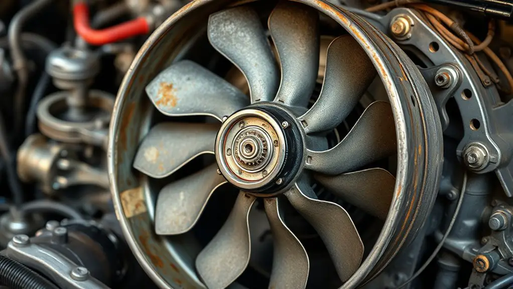
The visual inspection begins with a careful scan of the fan blades, hub, and housing for signs of wear, damage, or contamination. You assess blade straightness, tip rounding, and surface scoring, noting any cracks or delamination that could affect balance. Next, you verify hub integrity, checking for looseness, runout, or excessive play that might precede bearing failure. Inspect the housing for deformation, corrosion, and foreign material buildup that could impede airflow or create drag. Pay attention to mounting points and screws for looseness or misalignment, as vibration can propagate faults. Document any imbalance indicators, such as petal bending or blade contact with the housing, and evaluate the clearance between blades and the shroud. This step emphasizes fan blade inspection and housing integrity without delving into electrical aspects. If anomalies are found, isolate them before proceeding, ensuring the unit remains safe and operable for further testing.
Check Electrical Connections and Wiring
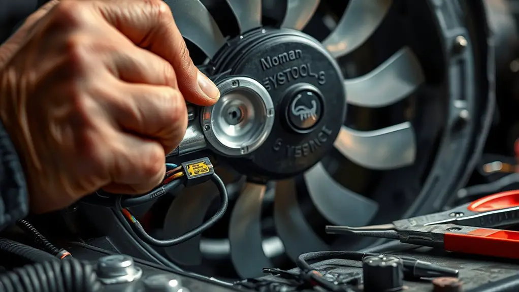
With the visual findings in mind, move on to checking the electrical connections and wiring. You’ll verify that all terminals are clean, tight, and free of corrosion, and that conductors are correctly routed away from moving parts. Begin at the power source and trace the path to the fan, inspecting junctions, crimped splices, and connector housings for any looseness or damage. Gently tug on conductors to confirm connection stability without stressing the insulation. Check for pinched insulation, stretched wires, or signs of heat discoloration that could compromise wiring integrity. Use an appropriate multimeter to validate continuity across each circuit segment, and verify that ground paths are solid and low-resistance. Document any deviations, replacing compromised components rather than patching defects. Re-seat connectors to ascertain repeated mating integrity, and recheck for proper seating after movement tests. Maintain safe clearances and avoid introducing new faults during reassembly.
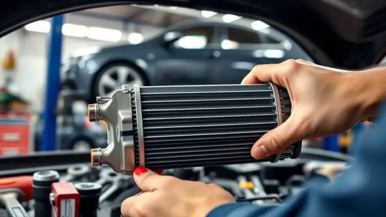
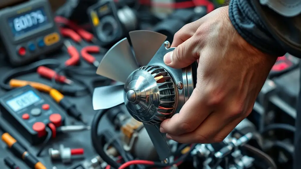
Inspect the Fan Motor for Signs of Wear
Inspecting the fan motor for signs of wear begins with a careful, stepwise assessment of mechanical and electrical condition. You’ll surface-check tolerances, lubrication needs, and insulation integrity to pinpoint potential failure before it escalates. During motor component inspection, identify loosened mounts, worn bushings, and bearing play that could introduce misalignment or overheating.
- Inspect mounting hardware for looseness or corrosion, then secure as needed.
- Check bearings and bushings for excessive play, noise, or heat, noting any binding.
- Examine windings and insulation for cracks, discoloration, or oil exposure, and test insulation resistance.
- Verify rotor and stator alignment, shaft runout, and balance to detect eccentric wear.
Document findings with precise measurements and establish thresholds for replacement. Prioritize observed wear patterns, correlating them with operating conditions from your pressure tests. Maintainers pursue proactive motor condition knowledge, ensuring you’re prepared to schedule repairs before reliability degrades. This approach supports fan motor wear awareness without overreacting to minor variances, reinforcing a controlled, freedom-respecting maintenance mindset.
Test for Audible or Vibration Clues
Audible and vibrational cues can reveal hidden faults that visual checks miss, so proceed from the motor inspection with a focused listen-and-feel approach. You’ll listen for tonal changes, irregular whines, or sudden surges in pitch as the fan runs under test conditions. Use a steady, controllable load to provoke consistent responses you can compare against baseline notes. During operation, note any rasping, grinding, or metallic squeals that accompany rotation, and correlate them with motor speed or load changes. Concurrently perform gentle palpation near bearing housings and mounting points to feel for unusual vibration transmission without forcing contact. Document audible signals and amplitude shifts, then apply vibration analysis concepts to distinguish rotor imbalance, misalignment, or bearing wear from incidental environmental noise. Prioritize reproducible observations, quantify relative loudness, and track changes over time. This disciplined approach supports diagnosing fault progression while preserving safe, controlled testing conditions.
Establish a Controlled Pressure-Test Setup
Begin by ensuring a Safe Test Environment with clear access, non-conductive surfaces, and proper personal protective equipment before any testing. Next, select Appropriate Load Simulation that matches the fan’s operating range to reproduce real-world conditions without over-stressing the unit. Finally, set up Accurate Data Recording to capture force, speed, current, and temperature at consistent intervals for repeatable analysis.
Safe Test Environment
When establishing a controlled pressure-test setup, start by selecting a dedicated workspace with ample ventilation and a nonflammable surface, then confirm all power sources are isolated and secured before any testing begins. You’ll maintain a safe testing mindset by enforcing a controlled environment that minimizes risk and instrumentation drift.
- Secure enclosure and barriers to prevent accidental contact
- Verify tools and meters are rated for the expected pressure range
- Establish a clear, coded procedure for initiating and aborting tests
- Document all readings, dates, and personnel involved for traceability
Keep PPE on, monitor temperatures, and limit onlookers to trained personnel. This disciplined approach guarantees safe testing while preserving a controlled environment for repeatable results.
Appropriate Load Simulation
To simulate load conditions accurately, select a load that mirrors the electrical and mechanical demands the fan will encounter in service, including startup surges and steady-state current. You’ll establish a controlled load profile that reflects real-world usage, avoiding oversimplified resistance alone. Use adjustable test resistors, electronic loads, or calibrated power meters to reproduce both peak and continuous demands. Document load characteristics before each run, ensuring repeatability and traceability. Monitor current, voltage, and temperature with high-resolution sensors, correlating values to fan performance under load. Maintain tight control on ramp rates to prevent artificial transients that could skew results. This approach yields meaningful data for diagnosing faults and validating performance expectations without overcomplication. Clear, reproducible results empower effective, targeted maintenance decisions.
Accurate Data Recording
Establish a controlled pressure-test setup by defining a disciplined data-recording protocol that captures every relevant parameter with high fidelity. You’ll guarantee traceability, repeatability, and clear comparison across test runs. Embrace disciplined data collection to reveal root causes and actionable insights.
- Define sensor placement and sampling rate for all signals, including pressure, current, voltage, temperature, and rotor speed.
- Standardize units, time stamps, and metadata so every run aligns with a common frame of reference.
- Use calibrated instruments and document calibration certificates to support data integrity.
- Record recording techniques, backups, and versioning to prevent data loss and enable audit trails.
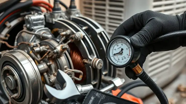
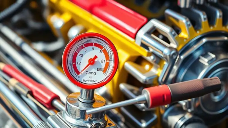
Perform a Baseline Pressure Readout
Before proceeding with any testing, obtain a stable baseline by measuring the fan’s operating pressure under normal, unloaded conditions. You’ll establish baseline performance through a controlled pressure measurement, ensuring the system isn’t driven by windage or resistance beyond its typical load. Record static pressure, dynamic fluctuations, and temperature indicators, then compare against expected manufacturer values. Use the baseline to normalize future readings, flagging deviations that suggest seal leaks, obstructions, or motor drift. Maintain consistent measurement points and intervals, and document environmental conditions to preserve repeatability. The goal is a precise reference that supports objective fault isolation without overinterpreting transient spikes.
| Concept | Action |
|---|---|
| Baseline target | Capture under unloaded, steady state |
| Data points | Static pressure, dynamic pressure, temp |
| Tolerances | Align with spec or historical norms |
| Validation | Repeat measurements for consistency |
| Documentation | Timestamped, labeled datasets |
This approach yields a concise pressure measurement framework, empowering you to interpret subsequent tests with confidence while preserving your freedom to troubleshoot.
Introduce Graduated Load While Monitoring
As you move from establishing a baseline, introduce graduated load while monitoring to reveal how the fan responds under progressively heavier demands. You’ll apply phased load steps and observe current, voltage, temperature, and audible cues using reliable monitoring techniques. This approach clarifies load management behavior and highlights thresholds before faults manifest.
1) Establish a safe ramp protocol: increment load in defined, repeatable steps and pause for stabilization between steps.
2) Record each step: document readings, environmental conditions, and observed anomalies with precise timestamps.
3) Inspect for non-linear responses: note delays, spikes, or drift in electrical or mechanical signals that indicate marginal performance.
4) Correlate results to limits: compare data against manufacturer specs and your baseline to confirm normal vs degraded operation.
Maintain clear communication with test personnel, verify instrumentation accuracy, and stay within safety margins. This methodical process strengthens diagnostic confidence without prematurely isolating fault sources.
Analyze Data to Isolate Faults
You’ll examine data patterns across test runs to spot reproducible signals that indicate fault boundaries. By correlating sensor readings with operational states, you isolate where anomalies originate and rule out upstream variations. This disciplined data approach directly supports fault isolation and speeds diagnostic decisions.
Data Patterns
Data patterns are the fingerprints of a fault, revealing whether anomalies stem from the motor, wiring, or control circuitry. You’ll use data trends and statistical analysis to chart where deviations align with expected behavior, then narrow the fault path with disciplined checks.
- Capture steady-state and transient signatures to compare against baseline expectations.
- Plot current, voltage, and speed correlations to identify phase shifts or skewed distributions.
- Apply statistical analysis to quantify variance, outliers, and confidence intervals.
- Cross-check temporal patterns with operating conditions to distinguish intermittent faults from normal fluctuations.
Fault Isolation
In fault isolation, you map observed data patterns from the previous data-pattern analysis to specific components or subsystems. You compare anomaly fingerprints—currents, voltages, and phase angles—with known fault signatures to pinpoint where deviations originate. Systematically cross-check readings under varied loads and speeds, documenting library matches and near-misses that guide narrowing. Employ isolation logic: rule out healthy pathways, confirm suspect branches, and converge on a single fault source. Record confidence levels for each candidate, then prioritize fault identification based on impact and accessibility. Once identified, plan an efficient fault rectification sequence that minimizes downtime and avoids collateral damage. Validate results through repeat measurements and functional tests. Maintain traceability, ensuring findings support future diagnostics and proactive maintenance decisions.
Document Findings and Next Steps
After completing the pressure-test, document the findings and outline the next steps with clarity. You’ll present objective results, identify fault indicators, and map each observation to actionable actions. This section prioritizes precision and practical guidance for independent technicians seeking freedom through clear science.
- Document findings: record voltages, currents, noise, and insulation integrity with timestamps and instrument calibration details.
- Assess fault causality: correlate symptom patterns with test data to confirm or rule out mechanical, electrical, or control faults.
- Define next steps: specify repair or replacement actions, required parts, and safety precautions before re-energizing.
- Plan verification: outline post-repair tests, success criteria, and a rollback option if outcomes deviate from expectations.
Maintain an audit trail, store data securely, and use plain language for cross-checks. You’ll gain confidence from repeatable, verifiable results that support independent troubleshooting and documented accountability. document findings, next steps.
Frequently Asked Questions
How Do You Verify a Horizontal vs. Vertical Fan Orientation for Testing?
You verify fan orientation by observing shaft alignment and airflow direction, ensuring the impeller plane matches the housing’s design. For testing methods, mount the unit level, then rotate slowly to confirm no binding while noting airflow vector. In horizontal orientation, airflow exits side or front as specified; in vertical, top-to-bottom. Use a tachometer and anemometer to record RPM and CFM. Document deviations, then adjust mounting or shims accordingly for accurate testing methods.
Can Non-Contact Methods Detect Motor Windings’ Insulation Integrity?
Non‑contact methods can’t directly detect insulation breakdown in motor windings. You should use insulation resistance testing or diagnostic winding tests for definitive results. Rely on non-contact testing to observe surface indicators like hot spots, arcing, or abnormal magnetic fields as supplementary evidence. If you suspect insulation degradation, perform insulation resistance measurements with appropriate equipment and follow safety protocols. Use these observations to guide further, precise testing rather than relying on non-contact methods alone.
What Leakage Test Confirms Housing Seal Integrity During Pressure Tests?
A conduit-style leakage test that confirms housing seal integrity is a pressure decay or pressurization method, where you monitor for a stable pressure drop over a defined interval. If pressure remains constant, you have housing integrity; a detectable leakage indicates compromised seal. So, perform a controlled pressurization, isolate the housing, and measure using a calibrated gauge. Document leakage rate precisely, compare to acceptable limits, and iterate repairs until seal integrity is established and housing leakage is within spec.
How to Differentiate Bearing Noise From Air-Flow Anomalies Quickly?
Around 60% of faulty fans feature bearing diagnostics clues before airflow issues, so you’ll start there. You’ll differentiate bearing noise from air-flow anomalies quickly by listening for consistent, pitch-stable sound during steady load, then isolate: run with reduced speed, compare suction vs. discharge, and note phase alignment. Use airflow evaluation data and vibration spectra to confirm. You’ll document tolerances, inspect seals, and verify lubrication intervals for precise, freedom‑driven maintenance.
What Safety Margins Apply When Increasing Test Pressure Beyond Normal Operating Range?
You should observe defined pressure limits and stay within documented safety protocols when increasing test pressure beyond normal operating range. Use measured increments, monitor for leaks, vibration, or component strain, and stop if any anomaly appears. Adhere to pressure limits, implement lockout-tagout, and follow safety protocols for PPE and flow control. Maintain a controlled environment, document deviations, and never exceed manufacturer guidance. Your rigorous approach protects personnel, equipment, and system integrity while preserving operational freedom.