How to Test ABS Pump With a Diagnostic Flowchart Before Replacement
To test an ABS pump before replacement, start by gathering tools and securing a safe workspace, then retrieve fault codes and live data from the ABS module. Inspect electrical connections, verify power and grounds, and watch for corrosion or loose pins. Validate the hydraulic system by observing pump response, pressure, and duty cycles during braking. Isolate upstream sensors, document results, and compare against known-good references. If discrepancies persist, you’ll gain clarity on next steps and repair options.
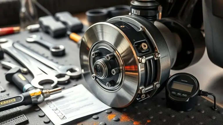
Step 1: Gather Tools and Safety Precautions

To begin, gather the essential tools: a jack or jack stands, wheel chocks, a service manual, a digital multimeter, and a diagnostic scan tool compatible with ABS systems. You’ll approach this step with deliberate, evidence-based focus, prioritizing tool selection that matches your vehicle’s specifications. Verify tool calibration and condition before use, and confirm owner safety instructions in the manual. Establish a controlled workspace—flat surface, ample lighting, and unobstructed access to the test area’s power and fuses. Implement safety measures: secure the vehicle, disconnect the battery when required, and wear PPE. Create a defined workflow to document measurements, reference tolerances, and note any deviations. Avoid improvisation that could compromise accuracy. Organize cords and connectors to minimize trip hazards. This phase sets a verifiable baseline, reducing ambiguity in later steps. Precision in tool choice and safety protocols underpins reliable diagnostic results and aligns with a freedom-minded, evidence-based approach.
Step 2: Retrieve Fault Codes and Live Data

Begin by connecting your diagnostic scan tool to the vehicle’s OBD-II port and selecting the ABS/traction control module. You’ll retrieve fault codes and begin live data monitoring to quantify system behavior. Record any stored codes and note their freeze frame context, then clear or save them as needed for later comparison. Focus on fault code analysis to identify patterns, such as repeated wheel sensor, pump, or pressure faults, which guide your next verification steps. While monitoring, watch real-time ABS parameters (wheel speeds, pump current, modulator duty cycle) and map anomalies to actual mechanical events. Use concise observations to form a hypothesis about the fault’s origin and its reproducibility under test conditions.
| Fault indicators | Expected behavior |
|---|---|
| Codes present | Specific subsystem faults (sensor, pump, or wiring) |
| Live values | Normal wheel speeds; stable pump current |
Step 3: Inspect ABS Pump Electrical Connections
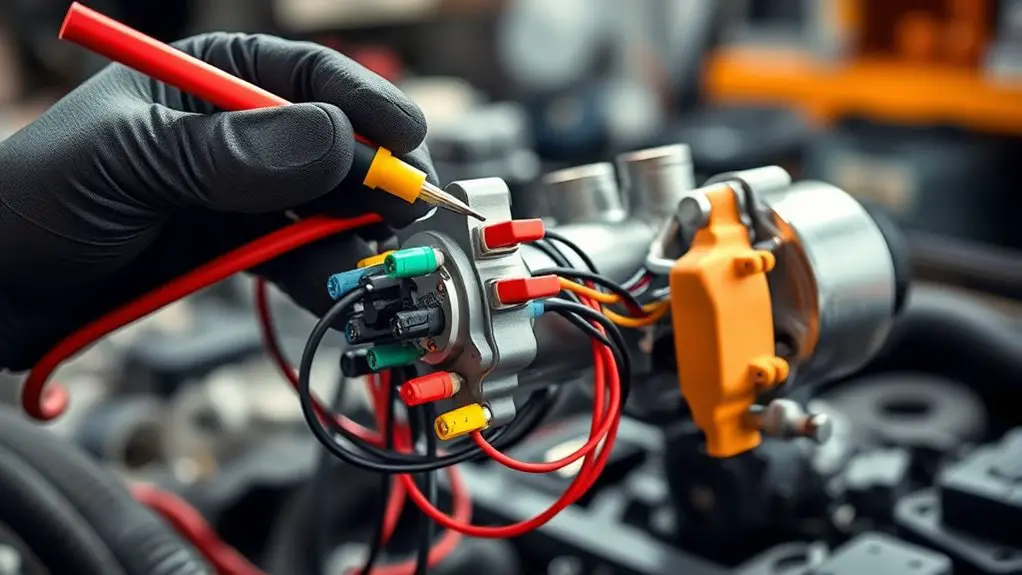
You’ll start by inspecting the wiring harness for any signs of wear, corrosion, or loose connections. Next, perform a connector integrity test to confirm pins are seated, terminals are clean, and there’s no continuity interruption. Finally, verify power and ground continuity to guarantee the ABS pump receives stable electrical supply.
Wiring Harness Check
Assess the harness that connects the ABS pump by inspecting every wire and connector for signs of damage, corrosion, or looseness. You should trace the entire loom from the pump to the main harness, noting any exposed insulation, pinched routes, or chafing against metal edges. Use a clean, bright light and magnification where needed, and document findings with color photos and precise descriptions. Check for continuity across each circuit without applying live power; note any open or shorted lines, and test ground paths as applicable. Look for connector corrosion at termini, verifying that terminals seat firmly and locks engage fully. Record resistance readings and compare to spec, focusing on wiring continuity and secure connections rather than guesswork. Correct any degraded segments before proceeding to functional checks.
Connector Integrity Test
The next step is to inspect the ABS pump electrical connections themselves. You’ll verify that each connector seats fully and locks without obvious damage. Examine pins for corrosion, bent blades, or loose termini, and compare against the service diagram. Use a bright light and magnification if needed, and disconnect only one harness at a time to avoid cross-connection errors. Perform connector testing by probing contact areas with a calibrated multimeter or a dedicated diagnostic pin-out tool to confirm continuity on each circuit path. Look for consistent resistance values across similar channels and detect any open or shorted lines. Document findings with precise measurements, then correlate with sensor and actuator behavior. This is about signal integrity, not speculation. Maintain clean, dry connections and reassemble securely.
Power and Ground Verify
Power and ground verification is essential for reliable ABS pump operation. You’ll methodically confirm that the pump receives proper supply and return paths before diving into diagnostics. Begin with circuit testing by inspecting the harness for damaged pins, corrosion, and loose connections at the ABS pump connector. Ascertain the ground point is clean, solid, and bonded to chassis metal with a low-resistance path. Next, perform voltage measurement at the pump supply pin while the ignition is on and the pump is requested. Compare readings to the vehicle’s service specification; note any voltage drop along the circuit under load. If voltage is low or intermittent, trace wiring faults, compromised grounds, or blown fuses. Document findings for accurate fault isolation and safe replacement decisions.
Step 4: Check Power Supply and Grounds
Begin by confirming the ABS pump has a solid electrical path: verify battery voltage at the pump connector and inspect all ground points for cleanliness and secure attachment. You’ll check the power supply by measuring steady voltage within spec while the system is idle and during active pump signals, noting any drops or spikes. Document readings and compare them to vehicle service data to identify borderline conditions. Next, assess ground integrity: inspect chassis and pump grounds for corrosion, loose fasteners, or damaged wiring, and guarantee straps or studs are tight and continuous to the battery negative. Use a multimeter to test continuity between the pump ground and the vehicle chassis, resolving any high resistance findings before proceeding. If voltage or ground issues are detected, address them with proper replacements or cleaning, then recheck. This step guarantees reliable electrical support for the ABS pump, reducing the risk of intermittent operation and downstream diagnostic confusion.
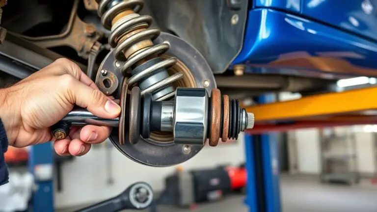
Step 5: Validate Hydraulic System and Pump Operation
To verify the hydraulic side, confirm the ABS pump is commanded and responding by observing system pressure and channel-specific duty cycles during controlled braking maneuvers, while ensuring flow integrity through the pump and Solenoids. You’ll inspect pump operation under simulated deceleration, watching pressure rise, plateau, and any transient dips. Compare measured values against manufacturer specifications for each channel, noting discrepancies that indicate flow restriction or valve sticking. Use a validated scan tool or data logger to capture real-time circuit pressures, pump current, and duty cycle proportions. Confirm that hydraulic fluid flow remains continuous when shifting between channels and that no air pockets or leaks compromise integrity. Document baseline performance with a steady-state stop and a gentle pulse maneuver to expose marginal seals or slow solenoids. If readings stay within tolerance and repeatable, you’ve authenticated the hydraulic system and pump operation for this phase, without over-interpreting intermittent fluctuations.
Step 6: Perform Pulsing and Pressure Tests
Building on verified hydraulic operation, you’ll apply controlled pulsing to the ABS channels while monitoring pressure responses and valve actuation. Begin with a planned pulse sequence that reproduces braking events without introducing risk. Use short, repeatable pulses to elicit valve response and to map channel compliance. Record baseline pressure, then initiate pulsing techniques with incremental amplitude and duration, watching for stable, repeatable pressure rises and falls. Compare measured pressure measurement data against expected hydraulic curves to detect lag, overshoot, or damping anomalies. Document valve opening and closing times, ensuring synchronization with channel pressure shifts. Maintain a controlled environment: secure connections, consistent pump speed, and clean hydraulic fluid. In your notes, emphasize reproducibility and traceability of results, and annotate any deviations from the standard model. Conclude by evaluating whether pulsing results support continued diagnostic progress or indicate the need for further isolation or replacement decisions.
Step 7: Isolate Upstream Components and Sensors
Isolating upstream components and sensors is essential to pinpoint the source of abnormal ABS behavior without confounding downstream hydraulic signals. You’ll methodically separate the sensor inputs and valve signals from the pump and modulator to observe each element’s true response. Begin by confirming power and ground integrity to upstream sensors, then test sensor wiring continuity and connector conditions for corrosion or damage. Use a known-good reference or scan tool data to compare sensor functionality against expected ranges, noting anomalies that appear before any output changes in the pump circuit. With the pump isolated, perform targeted diagnostics on wheel speed sensors, tone rings, and signal processors, ensuring clean, noise-free signals. Document observed deviations and correlate them with upstream diagnostics results. Maintain isolation during testing to prevent cross-talk from downstream components. This approach reduces ambiguity, supports accurate fault localization, and guides practical remediation decisions without overinterpreting sensor outputs.
Step 8: Interpret Results and Decide on Replacement or Repair
Interpret the diagnostic outcomes against baseline specs and observed fault codes to determine whether repair or replacement is warranted. Weigh repair feasibility, cost, and impact on safety, backing your decision with documented test results and component lifespan. Record the final choice and the supporting evidence in the vehicle’s service documentation.
Interpret Diagnostic Outcomes
Once you have the diagnostic data, start by confirming that the results are consistent across multiple tests and align with the vehicle’s symptoms. Then evaluate diagnostic outcomes with a methodical lens: look for repeatable patterns, corroborating sensor data, and corroborating ABS pump behavior. Perform fault code analysis to identify dominant codes and their sequences, distinguishing transient glitches from persistent faults. Correlate electrical readings, pressure data, and pump cycle timing to the code logic, ensuring the interpretation remains within OEM expectations and service bulletins. Weigh the severity against notable test currency, ruling out accessory causes before concluding. Document the rationale clearly, so you can justify whether repair or replacement is warranted based on objective evidence rather than impression. Maintain transparency for informed, freedom-driven decisions.
Decide Repair Vs Replacement
When deciding between repair and replacement, you should weigh the analyzed results against the vehicle’s fault history, diagnostic confidence, and OEM guidelines. You assess quantified faults, system interdependencies, and probable root causes, then forecast post-service reliability. If findings indicate isolated component degradation with feasible repair cost and stable performance, repair may be preferred. If root causes are vague, or if continued failures threaten safety or regulatory compliance, replacement is prudent. Consider risk of cascading issues, potential warranty implications, and time-to-resolution. Document anticipated outcomes, maintenance compatibility, and service life after intervention. Prioritize data-driven conclusions over guesswork, and align decisions with documented OEM parameters. Your ultimate aim is restoring reliable ABS function without unnecessary expenditure, while preserving overall vehicle performance and driver confidence, free to pursue informed choices.
Document Final Decision
Before finalizing the decision, compile and present a concise, evidence-based summary of the diagnostic findings, the evaluated repair options, and the projected outcomes.
- final assessment: synthesize test results, system behavior, and safety implications to justify the chosen path.
- replacement criteria: define when replacement is preferred over repair, based on reliability, cost, and risk.
- documented rationale: link each option to measurable indicators, not assumptions.
- next steps: outline actions to verify the decision, including post-repair testing and cautionary notes.
You’ll decide with clarity, prioritizing safety, reliability, and driver freedom. This final assessment should be objective, repeatable, and free from ambiguity, ensuring that the selected course aligns with both manufacturer guidance and real-world constraints.
Frequently Asked Questions
What Tests Confirm ABS Pump Motor Reliability Without Removal?
Yes, you can confirm ABS pump motor reliability without removal by performing non-invasive checks: observe pump operation during ABS events, listen for abnormal buzzing, and feel for consistent hydraulic pressure through diagnostic tools. Run system tests with appropriate scanners, monitor PID and current draw, and verify wheel speed sensor sync. Use fault codes, real-time data, and step-by-step flowcharts to document stability; if anomalies appear, consider more invasive checks. Maintain precision, evidence-based judgments, and freedom in decision-making.
How to Distinguish Pump Failure From Sensor Fault Indicators?
You can distinguish pump failure from sensor fault indicators by correlating pump diagnostics with sensor readings. Start with live data: if pump diagnostics show no current draw or abnormal PWM while sensor readings are within spec, suspect pump. If readings spike or drift while pump remains steady, suspect sensors. Cross-check wheel-speed data against ABS fault codes, verify wiring continuity, and re-test after reseating connectors. Document evidence, repeat tests, and consider replacement only when results are reproducible.
Can Hydrauilic Pump Leaks Mimic Electrical Faults?
Yes, hydraulic pump leaks can mimic electrical faults. You should treat a suspected hydraulic leak detection as a potential confounder in fault interpretation, since dropouts or noise may resemble sensor or pump signals. Verify by isolating systems, checking for pressure loss, and using electrical fault simulation tests while correlating with diagnostic data. If needed, perform controlled leak tests and document readings to avoid misdiagnosis, ensuring your conclusions stay evidence-based and repeatable.
Are There Safety Steps for High-Pressure System Testing?
Did you know 80% of high-pressure failures are preventable with proper safety steps? Yes—there are safety steps for high-pressure system testing. You should follow strict safety precautions and implement rigorous pressure management, using appropriate PPE, rated gauges, and isolation procedures. Confirm system depressurization before work, secure all fittings, and maintain a documented test plan. Monitor readings carefully, stop if anomalies appear, and verify leak checks after tests to protect yourself and equipment.
When Is Intermittent Pump Operation Acceptable in Diagnosis?
Intermittent operation can be acceptable in diagnosis only if you verify it against consistent fault signals and documented test results. You should observe repeating patterns, confirm with diagnostic data, and rule out sensor or wiring issues before concluding. If the pump runs sporadically without corresponding ABS events, treat it as non-acceptable until reproducible failures are captured. Document conditions, use controlled testing, and rely on evidence-based steps to support an acceptable diagnosis.