How to Use a Refrigerant Leak Detector to Find Refrigerant Leaks Causing Electrical AC Faults
To find refrigerant leaks causing electrical AC faults, power up the detector and let it warm, then methodically scan likely leak areas—joints, coils, and electrical connections—keeping the sensor close but not touching surfaces. Move from suspected spots outward and document ppm readings with precise time stamps. Recheck tightened or resealed areas, and compare readings with component sensitivity and service history. After isolating traces, confirm with electrical tests and more testing steps ahead. You’ll uncover more soon.
Understanding How Refrigerant Leak Detectors Work in Electrical AC Fault Scenarios
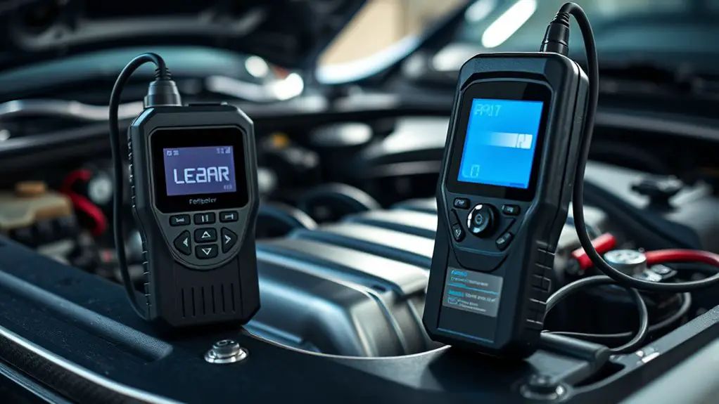
Refrigerant leak detectors identify trace amounts of refrigerant in the air, which typically indicates a system leak. You’ll use this baseline to understand how detectors respond in electrical AC fault scenarios. First, know the detector’s core: it measures refrigerant properties that differ from ambient air, signaling leakage patterns near electrical components. Next, grasp leak detection technology: electrochemical, halogen, or infrared sensors each have strengths for spotting specific refrigerants and concentrations. In practice, place the wand close to suspected junctions between electrical hardware and tubing, but keep loads running within safe limits. You’ll interpret readings by relative changes, not absolute numbers alone, recognizing that electrical arcing or heat can influence sensor output. Calibrate and test regularly to preserve accuracy across conditions. Remember: detector performance hinges on correct refrigerant type knowledge, ambient conditions, and timely interpretation, ensuring you isolate leaks without unnecessary teardown.
Signs That Refrigerant Leaks Are Contributing to Electrical Issues
If a refrigerant leak is present, you’ll often see electrical issues arise from altered cooling performance and overheating, which stress components and trip protective devices. You’ll notice quicker compressor run times, higher discharge temperatures, and more frequent thermostat cycling as the system tries to compensate. Electrical issues tied to refrigerant leaks typically show odd voltage readings, capacitor wear from abrupt load changes, and blown fuses during startup.
| Symptom | Practical check |
|---|---|
| Increased run time | Compare current cycle length to baseline and note longer on-times. |
| Overheating components | Feel exterior surfaces for unexpected heat; monitor with IR if available. |
| Irregular voltage or trips | Check for voltage drops at the contactor; inspect wiring for heat damage. |
| Reduced cooling | Compare indoor setpoint to actual air temperature; verify refrigerant level. |
| Acoustic changes | Listen for unusual fan or compressor noise during operation. |
These signs point to refrigerant leaks contributing to electrical issues; address leaks first, then reassess performance.
Preparing Safety Gear and Equipment Before You Start
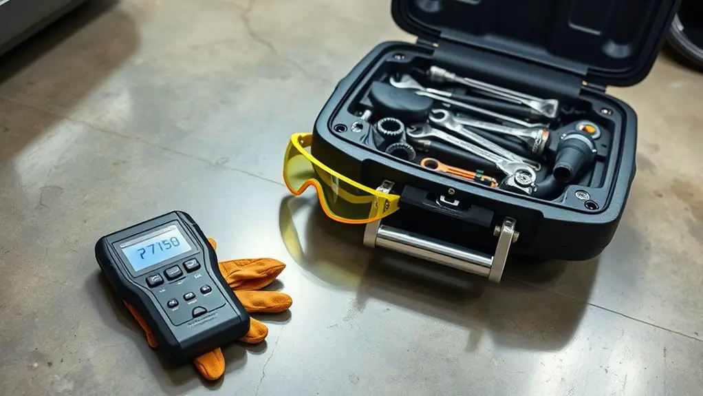
Before you start, assemble your safety gear: gloves, eye protection, and a respirator or cartridge mask as needed for your environment. Do a quick Equipment Readiness Check to verify batteries are fresh, detectors are calibrated, and hoses or probes are intact. Complete a Pre-Job Hazard Assessment to identify spill risks, electrical clearance, and ventilation requirements, so you can work with a clear safety plan.
Safety Gear Essentials
Gear up with the essentials you need before you start: eye protection, gloves, and a breathable, long-sleeve shirt to guard against leaks and sharp edges. You’ll also want a properly fitted respirator or mask if you’re sensitive to fumes, and hearing protection if you’re in a noisy shop. Keep safety gear within arm’s reach: goggles, cut-resistant gloves, and a sturdy apron or coveralls. Protective equipment should fit well and be free of damage. Inspect for tears, cracks, or missing fasteners, and replace as needed. Store everything in a dedicated kit to reduce search time. Wear closed-toe shoes with good grip. This setup supports precise fault finding while maintaining freedom to move and troubleshoot confidently.
Equipment Readiness Check
Begin by confirming all safety gear and equipment are accessible and in good condition before you start, so you can work without interruptions. You’ll verify that your refrigerant leak detector is calibrated, fresh batteries installed, and spare parts on hand. Inspect hoses, probes, and test caps for wear, cracks, or corrosion, and replace damaged items immediately. Check the detector’s response on a known standard to confirm sensitivity and zero drift, and document the result for accountability. Ascertain personal protective equipment fits properly and is within reach, including gloves, eye protection, and a respirator if required. Maintain a clean workspace to support quick, accurate checks. Practice equipment maintenance and leak prevention discipline to reduce downtime and improve fault isolation efficiency.
Pre-Job Hazard Assessment
Pre-job hazard assessment starts with a quick, targeted check of safety gear and equipment to guarantee you can work without interruption. You’ll verify PPE fits, gloves, eye protection, and respiratory gear if needed, plus confirm fire-safe footwear and a hard hat. Inspect the refrigerant leak detector for battery health, calibration status, and sensor integrity, and ascertain spare batteries are charged. Check tools, connectors, and leak-sensing probes for damage. Clear work areas of clutter and confirm venting and electrical safety compliance. Perform hazard identification by scanning for potential exposure routes, then conduct risk evaluation to prioritize controls: shutdown power where appropriate, isolate the area, and establish a communication plan. Document findings to guide a clean, safe start.
Identifying Potential Leak Paths in the AC System
You’ll start by checking common leak paths, focusing on where refrigerant lines run and joints that tend to loosen over time. Look for aged connections and wear at fittings, valves, and seals as you inspect for signs of leakage. Don’t neglect duct and coil joints, since small gaps there can mask larger issues down the line.
Common Leak Paths
Common leak paths in an AC system are predictable, so start by inspecting the joints and connections where refrigerant lines meet the condenser, evaporator, and fittings. You’ll zero in on seals, flares, and welds, then use your leak detection technology to confirm any suspicions. Keep in mind common refrigerant types influence the scent, odor, and response of your detector, so know what you’re chasing. Stay systematic: trace each line from the compressor through the condenser, then to the evaporator coil, and back. Tighten, reseal, or replace as needed, and recheck with your detector. You’re after crisp joints and clean fittings, free of oil residue that hints at slow leaks.
- Joints at condenser connections
- Fittings and flare points
- Sudden pressure drops near the evaporator
Aged Connections Wear
Aged connections wear is a common leak path because over time seals, flares, and welded joints loosen and lose integrity. You’ll inspect joints, fittings, and terminations for movement, corrosion, or heat discoloration, then test with your detector as you monitor for pressure drift. Connection degradation shows up as tiny, repeating pulses on the sensor or a slow, steady baseline rise in refrigerant trace. Look for rust at threaded interfaces, green or black residue, and brittle insulation near electrical leads. When you find suspect areas, isolate circuits, clean surfaces, reseal or replace components, and recheck. Electrical corrosion reduces conductivity and accelerates leaks, so don’t overlook loose grounds or shield damage. Document findings, then pursue targeted repairs to restore system integrity and prevent future faults.
Duct and Coil Joints
Duct and coil joints are common leak points because vibrations, temperature swings, and improper assembly can loosen seals and welds over time. You’ll inspect for gaps, residue, and corrosion at connections, flanges, and elbows, then verify with a detector in sweep mode along seams. Focus on duct insulation, as pinches and crushed insulation can hide leaks and raise system pressures. For coil maintenance, check micro-cracks in welded joints and junction points where refrigerant lines meet the coil frame. Treat loose fittings as a trigger: tighten per spec, re-seal with appropriate compounds, and re-check for leaks. Safety first: depressurize if needed and don’t bypass test steps.
- Visible gaps and frayed insulation near joints
- Loose flanges or misaligned coil connections
- Cracked welds or damaged seals around bends
Using the Detector to Locate Leaks Without Damaging Components
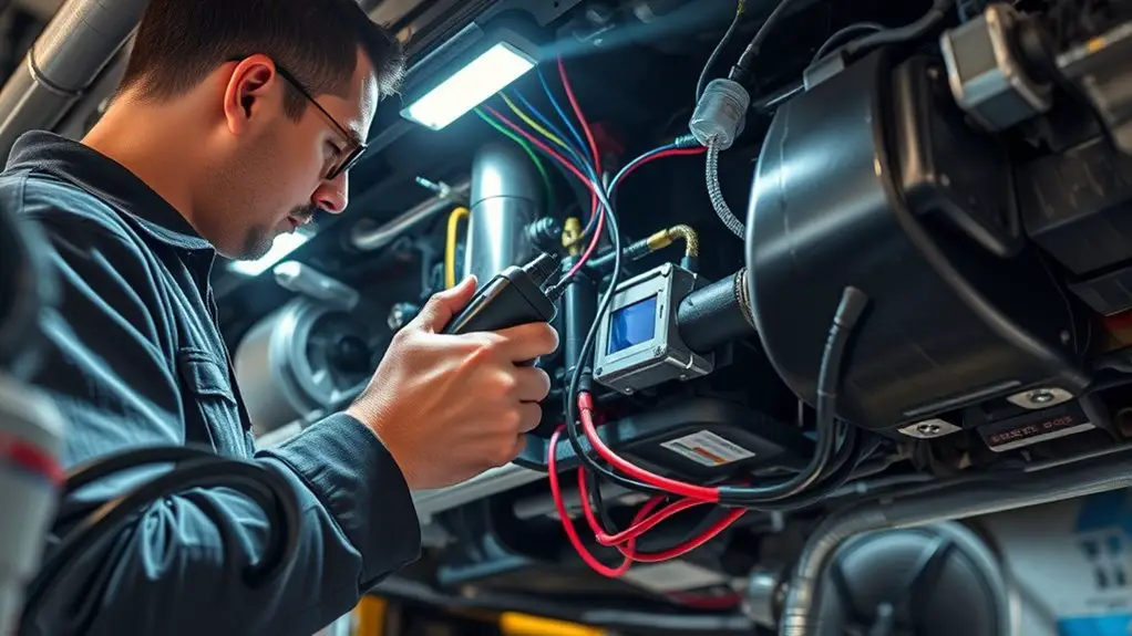
To locate leaks without damaging components, start by powering the detector and letting it warm up to its operating temperature, then scan methodically from the most likely leak areas outward. You’ll favor leak detection techniques that minimize disruption, keeping movement deliberate and steady to avoid brushing against sensitive parts. Move along joints, fittings, and valve seals, pausing at any bubble, color change, or audible cue. Use non invasive methods first—hold the sensor close but not touching surfaces, and sweep in slow, overlapping passes to build a true map of suspect zones. Document findings with reference points on the system—service ports, electrical enclosures, and insulation boundaries—so you don’t recheck irrelevant areas. If you detect a trace, isolate the area and recheck after tightening or resealing. Prioritize safety: depressurize per procedure, then recheck to confirm the repair. Maintain clean, controlled work, and return the system to service only when readings are stable.
Interpreting Detector Readings: What PPM Levels Mean for Electrical Components
Once you’ve located leaks with the detector, the next step is interpreting what the readings mean for electrical components.
- ppm significance: small numbers still matter near coils, relays, and contacts; understand that leakage sources can degrade insulation or insulation resistance over time.
- Detector calibration: verify the unit is calibrated to the correct refrigerant; a miscalibrated meter can mislead you about actual exposure and trigger points.
- Practical thresholds: use manufacturer guidance to relate ppm to fault risk; higher readings near terminals warn of accelerated arcing, overheating, or corrosion risk.
Keep readings in context with component sensitivity and service history. If a reading is borderline, recheck after a cooldown or with a fresh sensor response to verify persistence. Document the data, correlate with symptom onset, and avoid chasing “phantom” leaks. Your aim is actionable clarity: translate ppm into concrete maintenance actions that protect electrical integrity while preserving system freedom to operate.
Verifying Leaks Through Electrical Testing and System Diagnostics
Electrical testing confirms leaks by correlating detector readings with actual electrical behavior and system diagnostics. You’ll verify suspect zones by watching for coincidences between abnormal current draw, voltage dips, or abnormal relay activity and elevated refrigerant readings. Use a systematic approach: map symptoms to components, then conduct targeted tests rather than random probing. Detective techniques include isolating branches, performing continuity checks, and measuring resistance changes when a suspected leak affects load. Correlate outdoor and indoor circuit behavior with refrigerant hotspot locations identified by the detector to confirm leak paths. Document time stamps, readings, and component responses to build a clear leak identification narrative you can trust. Maintain clean test conditions, log ambient temperature, and avoid introducing extra variables. If readings drift independently of electrical behavior, recheck sensor calibration and wiring integrity. This disciplined method reduces false positives and tightens your diagnosis without guessing.
Practical Steps to Repair, Recharge, and Re-test the System
If a leak is confirmed, start with a focused repair plan, then safely recover refrigerant, recharge to spec, and re-test for integrity. You’ll follow the steps with discipline: seal the system, replace faulty components, then confirm there are no additional escapes using targeted leak detection techniques. Choose the correct refrigerant types for your unit, match oil compatibility, and keep all seals clean and intact. After repairs, evacuate the system to remove air and moisture, then recharge to spec and monitor pressures and temperatures during the re-test. Verify both electrical and thermal performance, and document readings for future reference. Precision matters—typo-free labels and correct charge weights reduce repeat faults. If you detect soft or rising pressures, halt and re-check. Maintain safe practices and proper PPE throughout.
- Focused repair plan with component replacement
- Safe refrigerant recovery and precise recharge
- Rigorous re-test and documentation for continued reliability
Preventive Measures to Avoid Future Refrigerant-Related Electrical Faults
Preventive measures start with good system design and disciplined maintenance to keep refrigerant-related electrical faults from happening in the first place. You’ll want robust component selection, secure electrical connections, and clear labeling so faults are easier to trace. Implement a proactive schedule that emphasizes preventive maintenance and minimizes ad hoc fixes. Use low-leak, high-quality fittings and brazing practices that reduce stress on joints, and verify that the electrical harnesses tolerate vibration and temperature swings. During commissioning, confirm proper refrigerant charge, correct pressures, and functional safety interlocks to prevent smear‑the‑fault scenarios. Establish a maintenance cadence built on regular inspections and field checks that identify insulation wear, corrosion, and connector looseness before they fail. Document findings, set repeatable thresholds, and train technicians to interpret detector readings with context. Keep records accessible, act on deviations promptly, and replace aging components before they become performance hazards.
Frequently Asked Questions
Can Leak Detectors Differentiate Refrigerant Types in Mixed Installations?
Yes, some leak detectors can differentiate refrigerant types in mixed installations, but capabilities vary by model. Look for refrigerant identification features and sensor specificity for mixed gases. You’ll rely on the detector’s ability to tag identified substances and alert you to separate leaks. Practically, confirm with calibration and known test mixtures. In troubleshooting, use refrigerant identification data to guide system recovery, avoid cross-contamination, and plan targeted repairs for mixed-gas scenarios.
How Do Ambient Contaminants Affect Detector Accuracy During Electrical Faults?
“Where there’s a will, there’s a way.” Ambient contaminants can skew detector accuracy during electrical faults, reducing detector sensitivity and masking leaks. You’ll want to account for ambient air quality by calibrating in clean air, replacing filters, and guarding against lingering vapors. Keep the probe oriented to avoid cross-contamination, perform baseline checks, and document deviations. With careful setup, you’ll trust readings and troubleshoot efficiently in real-world conditions.
Are There Hazards if Detectors Trigger Near Energized Components?
Yes, there are hazards: detectors triggering near energized components can pose electrical risks and arc-flash dangers. You should prioritize detector safety by keeping hands dry, wearing PPE, and following manufacturer instructions. Avoid touching live parts, and isolate power when feasible. Use non-sparking tools, work from a safe distance, and test the area with approved methods. If you must proceed, monitor for heat or smells, and be prepared to de-energize the circuit.
What Maintenance Cadence Keeps Detectors Reliable in Workshop Environments?
You should follow a regular maintenance cadence: inspect weekly, calibrate monthly, and replace sensors per the manufacturer’s schedule. For detector storage, keep it in a protective case, in a cool, dry place, away from solvents. Maintain documented logs and adhere to maintenance schedules, especially after extended nonuse. A proactive routine minimizes false alarms and guarantees reliability in workshop environments, letting you troubleshoot faster and keep freedom to work without unexpected downtime.
Do Detectors Require Calibration After Long Storage or Transit?
Yes, detectors require calibration after long storage or transit. You should perform detector calibration before use, especially after extended idle periods, to guarantee accuracy. Check storage conditions—keep in a cool, dry place and avoid exposure to contaminants. If drift is detected, recalibrate per the manufacturer’s procedure and verify with a known leak standard. Regularly log calibration dates, and don’t rely on returns-to-service without confirmation. Your freedom hinges on reliable readings, not guesswork.