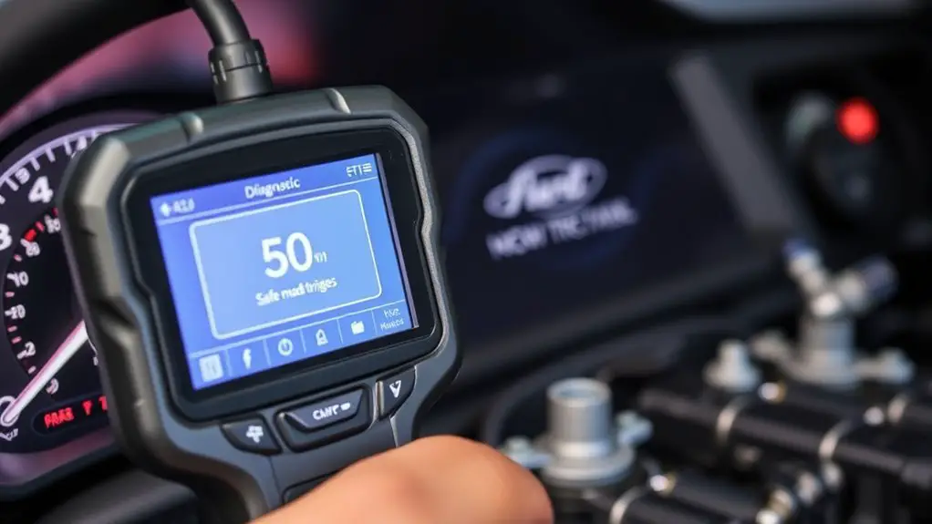
Step-By-Step: Using a Manufacturer-Level Scan Tool to Diagnose ECU Going to Safe Mode
You’ll use a manufacturer-level scan tool to quickly identify why the ECU entered safe mode, verify fault codes, and validate live data against OEM references to establish the fault hierarchy. Start by accessing stored and pending codes, then cross-check each against known safe-mode triggers. Monitor live data streams for voltage, temperature, and injector activity, noting patterns and freeze-frame timestamps. Establish a repair plan, perform fixes, clear codes, and confirm stability across idle and load. More detail awaits if you continue.
Understanding Safe Mode Triggers and Why ECUs Enter It

Safe mode is a protective state triggered when the ECU detects conditions that could compromise engine control or safety. You’ll analyze how the system interprets sensor data, fault codes, and boundary limits, then identify why the ECU shifts into restricted operation. Safe mode triggers arise from critical faults: loss of critical sensor input, sensor fault, maladaptive fuel trims, misfire patterns, and drivetrain safety concerns. You’ll examine how the ECU prioritizes stability over performance, preserving drivability while preventing damage. ECU behavior in safe mode typically includes reduced torque delivery, limited RPM, fixed injector timing, and disabled nonessential functions. You’ll verify whether the trigger is a single persistent fault or a cascade of intermittent events that accumulate to a protective response. Document the exact fault codes, timestamp sequences, and any conditional changes that accompany entry. Understanding these triggers enables you to map root causes, predict recovery steps, and plan safe, controlled diagnostics without compromising system integrity.
Tools and Access: What a Manufacturer-Level Scan Tool Includes

A manufacturer-level scan tool provides access beyond standard OBD functions, delivering deep diagnostic capabilities, bi-directional control, and access to vehicle-specific data streams that off-the-shelf tools can’t reach. You’ll see dedicated interfaces for ECU variants, module reprogramming, and live parameter monitoring at granular scales. Manufacturer level features include advanced diagnostic sessions, access to coded fault memories, and the ability to trigger specific actuators to validate subsystem behavior. You’re not limited to generic codes; you can view real-time sensor data, clocked in cycles, and timestamped events, which clarifies root causes when anomalies occur. Bi-directional control lets you command relays, inject fault signals, and test subsystem responses without external hardware. Expect secure access controls, tool licensing, and session handshakes that prevent unauthorized changes. This access clarifies diagnostic capabilities, ensuring you can reproduce conditions seen in safe-mode events, confirm ECU responses, and verify that recovery actions won’t compromise safety or integrity of vehicle networks.
Preparing the Vehicle: Safety, Documentation, and System Access

Before you begin diagnostic work, confirm the vehicle is powered down, secured, and that you have written safety protocols and access logs ready. Establish who is authorized to access the ECU and document each entry, change, or reset in a centralized log. This initial setup frames Safety Protocols, Access, and Logging so you can proceed to instrument connection and data retrieval with clear accountability.
Safety Protocols
To begin, you should verify the work area is secure and organized to prevent accidents and tool misplacement. Set up a dedicated bench, clearance around disconnects, and proper lighting to support precise diagnostics. Before power application, review vehicle-specific safety measures and defer to manufacturer guidance for hot surfaces, stored energy, and airbag systems. Establish a controlled workflow: isolate ignition, disconnect nonessential circuits, and ground yourself to minimize static. Document each step, including tool serials and ECU revision, to support traceability. Maintain readable labels on all connectors and protect wiring from accidental contact. During testing, follow diagnostic precautions: use manufacturer-approved adapters, avoid live-tiring situations, and log anomalies without altering configurations. Conclude with a quick safety recap and secure any used PPE.
Access and Logging
Accessing the ECU and establishing a reliable log begins with confirming the vehicle is safely prepared, the work area is organized, and all access paths are clear. You’ll establish a baseline by documenting vehicle status, tool serials, and session identifiers, then secure the environment to prevent interruptions. Use a manufacturer-level scan tool to access ECU interfaces, verify connector integrity, and enable write protections where applicable. Prepare a dedicated data logging channel, selecting appropriate timestamp formats and sampling rates to capture critical events without redundancy. Focus on scan tool benefits such as stable session management, reproducible parameter capture, and clear fault code narratives. Maintain an auditable trail by recording operator actions, tool configurations, and observed anomalies, ensuring data logging remains consistent across tests and revisions.
Retrieving and Interpreting Fault Codes: Step-by-Step
With the engine off and the tool connected to the ECU, start by selecting the fault/DTC menu and initiating a read of stored and pending codes. You’ll capture a concise list of fault codes, then move to interpretation with a calm, methodical approach. Prioritize fault code interpretation by cross-referencing each code against the vehicle’s typical failure modes and known safe-mode triggers. Keep your focus on reproducible, action-oriented steps rather than guesswork, and document every code before clearing any codes. Your goal is to build a clean fault narrative that guides subsequent checks.
- Identify primary vs. secondary codes to establish a fault priority
- Note freeze-frame data and timestamping for contextual clues
- Consider common patterns that prompt safe mode for the chosen model
- Record diagnostic tool selection and version to guarantee repeatability
Analyzing Live Data and System Parameters for Accurate Diagnosis
You’ll begin by observing live data streams for key parameters, focusing on voltage, current, temperatures, and sensor outputs. Maintain a systematic baseline, compare real-time values against manufacturer references, and flag any deviations that exceed defined thresholds. Use this ongoing data to guide diagnostics, prioritizing parameters most likely to indicate ECU or sensor faults.
Live Data Insights
Live data insights are the backbone of accurate ECU diagnosis: by monitoring real-time sensor readings, torque and RPM, fuel trims, injector pulses, timing, and system voltages, you can identify deviations that point to faults rather than transient fluctuations.
You’ll build a focused picture from continuous streams, spotting patterns that reveal when a parameter diverges from expected behavior. Track live data trends across cycles to distinguish intermittent faults from noise, and correlate them with operating modes for higher diagnostic accuracy. Prioritize stable baselines, compare to known-good curves, and document anomalies for verification. This disciplined approach keeps you aligned with the goal: precise, actionable insight that informs safe mode decisioning without overreacting to momentary spikes.
- Monitor sensor slew rates and cross-check with torque
- Compare live data trends against fault thresholds
- Correlate injector pulse widths with RPM and load
- Validate voltage rails under varying temperatures
Parameter Monitoring
Parameter Monitoring integrates live data streams with static system parameters to form a cohesive diagnostic picture. You’ll track parameter identification across channels, aligning sensor readouts with baseline values to expose anomalies. Use data correlation to verify that observed deviations map to expected system behavior, not random noise. Maintain consistent sampling intervals to preserve temporal relationships when ECU enters safe mode. Filter transient spikes, then confirm persistent trends before conclusions. Document each parameter’s unit, range, and relation to others to support repeatability. The goal is a clear, actionable map that guides investigation, not guesswork.
| Parameter | Insight |
|---|---|
| RPM, temps, fault codes | Correlated patterns indicate root cause |
| Voltage, fuel trim | Stability confirms ECM logic |
Verifying Repair, Clearing Codes, and Returning the ECU to Normal Operation
Once the repair steps are complete and the ECU has been verified on the bench or in-vehicle, you should clear any stored diagnostic trouble codes and reset learned data as appropriate, then re-test to confirm normal operation. You perform repair validation by rechecking sensor inputs, actuator responses, and fault log history to guarantee the issue is resolved and no new faults appear. Focus on code clearing to guarantee the ECU starts fresh, and confirm that learned values don’t reintroduce the prior condition. Validate timing, AFR, boost, or rail patterns against baseline references, and monitor for any intermittent signals. Document results, including vehicle behavior, scan results, and re-test outcomes, so you have auditable proof of completion. If everything remains clean, you may return to normal operation with confidence.
- Verify post-repair data stability and absence of DTCs
- Confirm baseline parameter alignment under load and idle
- Re-test across relevant operating ranges
- Log everything for future audits
Frequently Asked Questions
Can Safe Mode Be Triggered by Non-Ecu Faults, Like Battery Management?
Yes, safe mode can be triggered by non-ECU faults like battery management issues. About 60% of unexpected safe-mode events are linked to power or sensor anomalies rather than core MCU faults. You should evaluate battery health and power fluctuations first, since they can force protective states. Use diagnostics to monitor voltage stability, cranking surges, and alternator health, then correlate with fault codes to determine if the trigger lies outside the ECU core.
Are There Risks of Data Corruption When Retrieving Live Data?
Yes, there are modest risks to data integrity when retrieving live data. If the tool or session interrupts, buffers, logs, or timestamp integrity could be compromised. To minimize risk, you should enable proper read-only modes, verify firmware compatibility, and guarantee stable power and grounding. Use checksums or timestamp validation where available, and avoid writing data during capture. With careful sequencing, you preserve data integrity while you access live data.
How Long Should a Vehicle Stay in Safe Mode Before Diagnosing?
You should maintain safe mode only long enough to complete diagnostic procedures, then revert once data confirms stable operation. The safe mode duration depends on the vehicle’s fault codes and the complexity of the system, but you typically test in short, controlled intervals, documenting each step. Don’t rush; make sure you’ve cleared codes and verified sensor integrity before proceeding. If issues recur, extend diagnostic procedures and re-evaluate before normal operation.
Do Manufacturer Tools Auto-Update With Firmware During Diagnostics?
Yes, manufacturer tools can auto-update firmware during diagnostics in many setups. You’ll want to guarantee the diagnostic software handles incremental firmware updates without interrupting the session. Keep a current backup, verify connection integrity, and monitor update progress in real time. If auto-update is active, confirm it won’t reset fault data or alter calibration states. Schedule updates during a maintenance window to maintain traceability and preserve diagnostic continuity.
Can ECU Safe Mode Affect Immobilizer or Keyless Entry Functions?
Yes, ECU safe mode can affect immobilizer or keyless entry. When the ECU enters protection or recovery states, ECU communication with immobilizer transponders or keyless entry modules may be disrupted, causing locked ignition or delayed/faulty access. In testing, you’ll verify via diagnostic data lines and margined timelines; if communication drops, reinitialize modules and confirm synchronization. If immobilizer remains mismatched, diagnostic logs will show ECU communication errors related to keyless entry.


