Step-By-Step: Using a Manufacturer-Level Scan Tool to Diagnose Tool Compatibility Issues
Begin with Verifying Hardware Connections: inspect power and data cables, reseat connectors, and note any intermittent contact indicators. Then do a Protocol and Interface Check, confirming baud rates, parity, and supported standards, and build a compatibility matrix against the vehicle/ECU. Check Software/Firmware Versions, plan updates with rollback, and document all IDs and dates. Establish a Baseline Diagnostic Session before attempting any tests, and log DTCs and responses. If issues persist, you’ll uncover deeper insights and practical next steps.
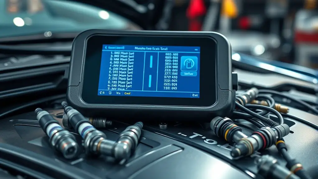
Verifying Hardware Connections

Start by visually inspecting all relevant hardware connections to ascertain they are seated firmly and correctly. You approach this with a methodical mindset, documenting each step as you go. Check power cables, data lines, and interface connectors for signs of wear, bent pins, or loose housings. Gently reseat every connection, listening for a subtle click that signals proper engagement. Verify that connector orientations match device guidance and that locking tabs engage fully. Observe any indicators on the tools or adapters; patterns of LEDs can reveal intermittent contact or partial failures. If you encounter resistance, stop and re-evaluate rather than forcing a fit. Record environmental factors that could affect contact stability, such as temperature or vibration. Conduct a brief test after each re-seat to confirm stability under load. This disciplined verification supports hardware troubleshooting and ascertains connection stability, forming a reliable foundation before deeper diagnostics. You maintain clarity, precision, and freedom in your workflow.
Confirming Supported Protocols and Interfaces
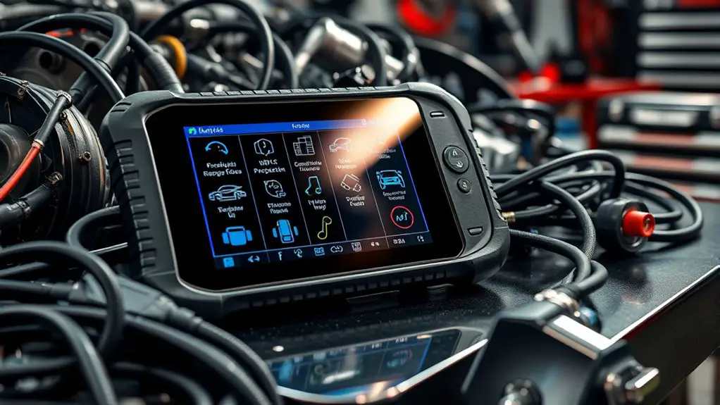
To begin confirming your tool’s capabilities, perform a Protocol Support Check to verify that the scan tool supports all required communication standards for your device. Next, run an Interface Compatibility Scan to guarantee physical and logical interface types align with the target hardware and software expectations. Document any gaps and plan remediation steps before proceeding with broader testing.
Protocol Support Check
Protocol support checks verify which communication standards and interfaces the scan tool can use. You’ll perform a careful cataloging of supported protocols, then cross‑reference with the vehicle and ECU expectations to minimize misreads and false negatives. This is where protocol analysis techniques come into play, letting you map capabilities to real-world use cases and data streams. Your compatibility assessment methods should be documented, repeatable, and auditable, ensuring each interface is validated under known conditions.
- Confirm supported vehicle protocols (ISO, CAN, LIN, KWP, UDS) and transport layers
- Verify message timing, baud rates, and error handling capabilities
- Record software/firmware compatibility and required calibration levels for protocol negotiation
Interface Compatibility Scan
The Interface Compatibility Scan begins by confirming which protocols and interfaces the scan tool can actually use, then aligns those capabilities with the vehicle’s communication expectations. You’ll map supported interface standards overview against the car’s ECU interfaces, verifying baud rates, handshakes, and message framing. Next, you assess diagnostic tool types involved, distinguishing OEM-style, generic, and mixed tool capabilities to prevent cross-protocol conflicts. You’ll document parity between CAN, LIN, K-Line, Ethernet, and USB modalities, noting any adapter requirements. Then you perform a capability cross-check: physical layer, data link layer, and application layer compatibility, ensuring error handling and timeouts align with vehicle expectations. Conclude with a precise gap report and a actionable remediation plan for reliable, consistent diagnostics.
Checking Software and Firmware Versions
When evaluating tool compatibility, start by confirming the exact software and firmware versions in use, since mismatches can prevent proper operation or trigger unexpected behavior.
You’ll verify both layers against the manufacturer’s compatibility matrix, documenting current revisions and release dates. Focus on precise build identifiers, not generic version labels, to avoid ambiguity. Next, assess the availability of software updates and firmware upgrades, noting any dependencies or required reboots. If versions lag, plan controlled updates during a maintenance window, ensuring rollback paths exist.
- Confirm current software build, firmware revision, and build date
- Check for official software updates and firmware upgrades with release notes
- Verify compatibility after each change and document any findings
Proceed with a minimal, repeatable checklist to reduce drift. If a mismatch exists, avoid ad hoc fixes; instead, align with documented procedures and test fixtures to validate operation before proceeding to broader diagnostics. Maintain clear records for audits and future reference.
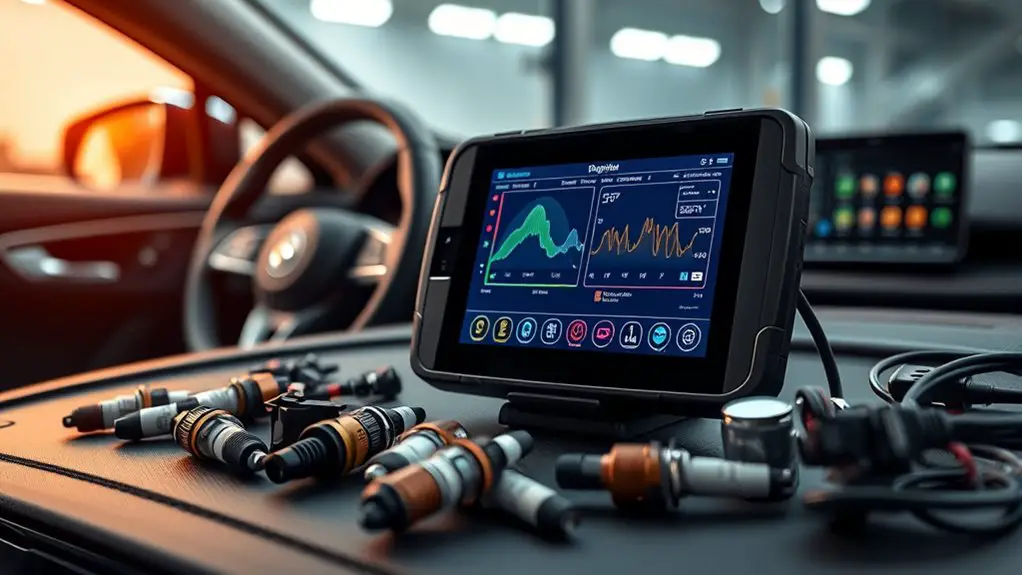
Establishing a Baseline Diagnostic Session
To establish a baseline diagnostic session, you’ll configure the initial parameters to mirror normal operating conditions. Set baseline diagnostic setup elements and record initial session parameters, including system state, active modules, and sensor readings. This baseline provides a reference for subsequent comparisons and tool compatibility checks.
Baseline Diagnostic Setup
Establishing a baseline diagnostic session involves defining a repeatable, sensor-backed snapshot of the system under normal operating conditions, so subsequent scans can reveal deviations. You’ll capture stable states, reference ranges, and consistent environmental factors to guarantee meaningful comparisons across sessions. The goal is to support reliable trend analysis and quick anomaly detection by using baseline diagnostic tools that align with specific vehicle or tool configurations. Focus on reproducibility, documentation, and repeatable measurement points to preserve diagnostic session importance.
- Reproducible sensor set and timing
- Documented reference values and environmental context
- Clear, repeatable start/stop criteria for each scan
Initial Session Parameters
Initial Session Parameters set the stage for a reliable baseline by defining the exact conditions and data points captured at the start of each diagnostic run. You establish the scope, select the vehicle profile, and lock hardware interfaces to prevent drift during collection. This phase defines initial session objectives, such as reproducible data capture, sensor troubleshooting, and protocol alignment with the OEM specification. You document timestamping, ECU communication modes, and data stream granularity to guarantee repeatability across sessions. Initial session considerations include safety checks, tool authorization, and known-good calibration references. You verify plugin integrity, confirm diagnostic modes, and set expectations for logging depth. By codifying these parameters, you create a stable reference frame that guides subsequent analysis and improves tool compatibility outcomes, without sacrificing efficiency or clarity.
Interpreting Diagnostic Trouble Codes and Messages
Interpreting diagnostic trouble codes (DTCs) and messages starts with a structured approach: identify the code, understand its meaning, and determine the appropriate action.
You’ll translate a code or alert into concrete steps, ensuring you separate symptom from fault. Focus on trouble code meanings and how each symbol maps to subsystem behavior, sensor input, or actuator state. Then assess diagnostic message interpretation, distinguishing cautionary notices from fault conditions and noting any freeze-frame data that informs context.
- Identify the exact DTC and subcode
- Correlate meaning with subsystem behavior
- Plan the minimal, safe verification steps
Proceed with a disciplined workflow: verify applicability to the vehicle or tool, cross-check with related codes, and document findings. Maintain a refusal-to-step-back mindset when data conflicts arise, and log any calibration or software caveats. This method keeps you aligned with engineering intent, enabling precise validation while preserving operational freedom.
Troubleshooting Communication Failures
When diagnosing communication failures, you’ll build on the DTC-driven approach by focusing on data link integrity, handshakes, and message timing between the tool and the target system. You’ll verify baseline protocol expectations, confirm proper baud rates, parity, and framing, then test retries and timeouts to isolate latency. Systematically log timestamps, error counters, and mismatch codes to distinguish compatibility issues from bus contention or electrical noise. Use troubleshooting techniques to reproduce failures under controlled loads, then iteratively adjust handshake sequences and message cadences until responses align with the tool’s expectations. Maintain strict change control and document outcomes for each protocol variant you test, avoiding assumptions about the underlying network layer. This disciplined method yields actionable evidence, guiding you toward precise compatibility decisions without overreach.
| Column A | Column B |
|---|---|
| Data link checks | Timing validation |
| Handshake discipline | Protocol conformity |
| Latency tracing | Error attribution |
Validating Vehicle and ECU Compatibility
Validating vehicle and ECU compatibility starts with a structured, evidence-driven approach. You’ll establish a baseline by confirming the target vehicle’s identity and known ECU specifications, then compare against tool capabilities to avoid gaps or mismatches. Focus on traceable data and repeatable checks, not assumptions, to guarantee a clean diagnostic path.
- vehicle identification: verify VIN, model year, and trim through official databases and documentation
- ecu specifications: confirm ECU family, software version, and security features align with tool support
- compatibility matrix: map tool-supported protocols, access levels, and diagnostic functions to the vehicle/ECU pair
Proceed with documentation of each comparison, recording dates, part numbers, and firmware levels. If discrepancies arise, flag them for targeted validation rather than broad testing. Maintain a disciplined, repeatable process to minimize false conclusions and preserve forward progress. This approach supports freedom by giving you concrete, auditable criteria for compatibility decisions and a clear path to reliable tool operation.
Reproducing Issues With Controlled Scenarios
Reproducing issues with controlled scenarios requires a disciplined setup that isolates variables and yields repeatable observations. You start with a defined baseline: the tool, vehicle interface, and test environment must be steady across trials. Establish a controlled chassis state, consistent ignition status, and repeatable load conditions to prevent external drift from masking true causes. Document each variable you alter, ensuring changes map to a single hypothesis about the tool’s behavior. Use repeatable sequences for initiating commands, recording responses, and measuring latency, timing, and error codes. Maintain deterministic data capture, sampling at fixed intervals and logging metadata such as tool firmware version, ECU revision, and ambient conditions. When issue reproduction occurs, replicate exact sequences from initial reports, then introduce incremental deviations only after full replays succeed. Emphasize traceability: link every observation to a specific controlled scenario, so patterns emerge without ambiguity and with actionable clarity for resolution.
Documenting Findings and Next Steps
Documenting findings and next steps requires a disciplined, traceable record of observations, decisions, and rationale. You’ll summarize what occurred, note any deviations, and justify each conclusion with concrete evidence. Use objective language and reference timestamps, tool IDs, and firmware versions to guarantee reproducibility. Emphasize finding patterns alongside isolated anomalies, so the narrative supports scalable action. When documenting errors, attach logs, screenshots, and diagnostic codes, and describe the exact steps that led to each result. Prioritize clarity over ambiguity to reduce follow-up uncertainty in future tests or audits. Your next steps should be actionable, measurable, and time-bound, including responsibilities and success criteria. Include risk flags and escalation paths for unresolved issues. Keep the record living: update it with new data, retest outcomes, and revised conclusions.
- Capture observations that indicate finding patterns and note any contrary data.
- Link findings to specific test cases and configurations.
- Outline corrective actions with owners and due dates.
Frequently Asked Questions
How Do I Verify Secure Authentication Between Tool and ECU?
To verify secure authentication between tool and ECU, you’ll confirm a secure connection using mutual authentication and verify credentials against the ECU’s expected certificates. Implement and log authentication protocols, inspect handshake messages, and guarantee session keys are derived correctly. Check TLS/DTLS or equivalent crypto methods, verify certificate trust chains, and confirm re-negotiation isn’t enabled insecurely. If mismatches occur, halt access, revalidate keys, and reestablish a trusted session with proper authentication protocols.
Can Tool Compatibility Vary by Vehicle Manufacturer?
Yes, tool compatibility can vary by vehicle manufacturer. You’ll face compatibility challenges due to differing manufacturer standards, even with universal interfaces. First, confirm supported protocols, CAN IDs, and data formats for each maker. Then test sequentially on target ECUs, documenting failures and workarounds. Maintain a rigorous baseline to compare against, and adapt procedures to evolving standards. This approach preserves your freedom while ensuring precise tool-to-vehicle interoperability across manufacturers.
Do I Need to Enable Vendor-Specific Diagnostic Modes?
Yes, you should consider enabling vendor-specific diagnostic modes. If a tool supports vendor diagnostics, enabling modes guarantees access to proprietary fault codes and live data. You’ll want to verify documentation for each vehicle family, then enable modes only when required for a given test. Keep in mind that enabling modes may affect security and compatibility; disable them after diagnosis to maintain baseline tool behavior and prevent unintended data access.
What Are Non-Obvious Latency Effects on Data Streams?
Data processing can reveal non-obvious latency: you’ll notice jitter as buffers fill, clock drift, and queueing effects that aren’t obvious from raw throughput. Transmission delays emerge from stack layering, protocol handshakes, and device-side rate limiting. You’ll also see bursty traffic interacting with window sizing, causing temporary stalls. Track timestamps, sequence gaps, and jitter metrics to quantify impact, then tailor buffering and scheduling to balance responsiveness with sustained data integrity for flexible, freedom-loving workflows.
How Should I Log Intermittent Tool Failures for Audits?
You should implement structured failure documentation that captures timestamped events, tool identifiers, error codes, and environmental context. Use portable logs with immutable backups and concise, procedure-aligned notes. Align entries with audit procedures by displaying the root cause, recovery steps, and verification impressions. Maintain a rolling log with versioning, access controls, and incident IDs. Regularly review gaps, rehearse incident drills, and guarantee traceability from failure onset to resolution for compliance and freedom to improve.