Step-By-Step: Replacing a Failing MAP Sensor That Causes White Smoke From Exhaust
To fix a MAP sensor that’s causing white smoke, start by confirming the sensor’s wiring harness and vacuum lines are intact, clean the area with isopropyl alcohol, and locate the MAP sensor near the intake or throttle body. Verify a stable 5V reference and a changing signal with engine load, then compare readings to OEM specs. Replace with a matching sensor, reconnect the harness securely, and perform a cautious test drive to confirm idle, fuel trims, and emissions look normal—more steps ahead.
Diagnosing White Smoke and MAP Sensor Symptoms

If you’re seeing white smoke and suspect a MAP (manifold absolute pressure) sensor issue, start by confirming the smoke isn’t from unrelated causes like coolant leaks or an overrich fuel condition. You’re aiming to isolate symptoms without guesswork. Note white smoke causes often stem from abnormal air-fuel ratios, misfires, or ECU misreads, not just a single faulty sensor. Observe exhaust color, timing adjustments, and rough idle patterns, then cross-check MAP readings with a scan tool. Look for persistent high or low manifold pressure readings when you’re cruising, idling, or under load. Sensor failure can masquerade as other problems, so compare MAP data to known baselines and fuel trims. If readings drift with ambient temperature or pressure, you may have a faulty sensor or wiring issue. Be systematic: document symptoms, verify with live data, and avoid replacing parts based on fear. Clear, decisive tests save you time and restore freedom on the road.
Tools and Safety Precautions

Before you start inspecting or replacing a MAP sensor, gather the right tools and set up a safe workspace. You’ll work lean and efficient, so keep disruptions to a minimum and stay focused on safety.
| Tools | Purpose |
|---|---|
| Ratchet, sockets, screwdriver set | Remove mounting hardware without damage |
| Multimeter or OBD reader | Verify electrical signals and drive data |
| Isopropyl alcohol, shop towels | Clean the sensor area and connectors |
| Safety gear, gloves | Protect hands and eyes during disconnects |
| Optional | Why it helps |
| Torque wrench | Reinstall to manufacturer specs |
| Sensor grease or dielectric grease | Improve seal and connection durability |
Safety gear, tool checklist: wear gloves, eye protection, and closed-toe shoes. Disconnect the battery before work, and keep a clear, well-lit workspace. Label connectors if you remove multiple plugs. Confirm tools are within reach, reduce last-minute searches, and avoid hurried grabs that cause slips. Stay deliberate, measure twice, and test once.
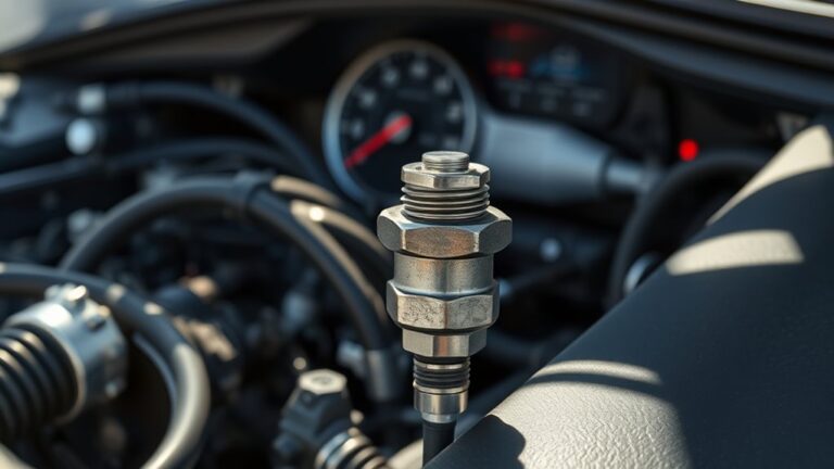
Locating the MAP Sensor in Your Vehicle

Start by locating the MAP sensor position on your engine bay; it’s typically near the intake manifold where vacuum lines connect. Identify the vacuum lines and trace them back to their hosing and fittings to confirm the correct route. Verify the electrical connector by checking the plug and its wires for secure, clean connections before you move on.
Locate MAP Sensor Position
The MAP sensor is usually tucked somewhere near the intake manifold or throttle body, so begin by locating the throttle body and follow the vacuum lines back toward the engine. You’ll spot the sensor mounted on a metal or plastic engine portion, with a small electrical connector plugged in. Check both sides of the intake plenum for the sensor, noting that different map sensor types share similar layouts. Once you locate it, note its orientation and the wiring harness routing to avoid damage during removal. This quick check helps you confirm sensor location and reduces guesswork. Table below summarizes common placements for clarity.
| Location | Visual cue | Common types |
|---|---|---|
| Near intake | Vacuum line run | MAP sensor types |
| On throttle body | Connector facing outward | Sensor location |
| On upper manifold | Aluminum bracket | Sensor location |
| Velocity/boost area | Nearby harness guard | MAP sensor types |
Identify Vacuum Lines
To identify vacuum lines and locate the MAP sensor, start by tracing the hoses that run from the intake manifold toward the throttle body and firewall. You’ll follow each line to where it tees or clips, noting connections to the manifold, vacuum reservoirs, and intake plumbing. Look for a vacuum line that routes close to the throttle body—this is your MAP sensor supply route in many vehicles. Gently wiggle hoses to confirm they’re seated and not cracked. If you sense stiffness or signs of wear, mark or photograph their paths for reference. For leak detection, run the engine briefly with a cap or finger over suspect ports and listen for changes in idle. Maintain clean surroundings and avoid forcing fittings.
Verify Electrical Connector
Locate the MAP sensor’s electrical connector by tracing it from the sensor body to the wiring harness. First, inspect the connector for any cracks, pin gaps, or melted housing, then verify it seats firmly to the sensor. Wiggle the harness gently to confirm there’s no looseness or detachment under load. If you see corrosion or bent pins, address them before proceeding. Next, disconnect and reattach with clean hands to guarantee a solid ground, and listen for a click that confirms engagement. Consider using connector cleaning techniques on the terminals if a dull or corroded contact is evident. Be mindful of electrical connector types you encounter, and choose compatible tools and sprays. This step prevents faulty readings that could mimic sensor failure.
Verifying MAP Sensor Electrical Connections
Since a MAP sensor relies on clean electrical signals, start by visually inspecting the wiring harness and connectors for damage, corrosion, or looseness.
You’ll check for bent pins, cracked housings, and melted insulation. Look for pulled or pinched wires and any signs of moisture intrusion. If you see corrosion, clean with electrical contact cleaner and resecure firmly. Verify the connector clicks when mated and that locking tabs are engaged. Wiggle the harness lightly to reveal loose connections or intermittent faults. Confirm that the MAP sensor ground is solid and that power and signal wires aren’t sharing with high-current circuits. Document any observed issues as common connection issues and address them before moving on. For troubleshooting tips, reseat connections and reseal weatherproof boots. Below is a quick visual guide to common scenarios.
| Symptom/Issue | Likely Cause |
|---|---|
| Intermittent idle | Loose connector |
| No signal | Damaged pin |
Testing the MAP Sensor With a Multimeter
After confirming the MAP sensor electrical connections, you’ll verify its readings with a multimeter to ascertain the sensor’s output matches spec. You’ll test for consistent voltage signals and a smooth response as you rev the engine. This is map sensor testing done with focused intent, not guesswork, so you’ll keep the readings tight and actionable.
1) Observe the reference voltage at 5V and ground, confirming there’s no short or open circuit.
2) Monitor the signal line’s voltage as you vary engine load, ensuring a steady ramp without drops or spikes.
3) Compare actual values to the OEM spec sheet, documenting any deviation to inform the replacement decision and avoid false positives.
Tips: use a fresh battery, a stable ground, and a clean connector. If readings diverge consistently, plan for a replacement and recheck after installation to validate multimeter usage and overall MAP sensor testing accuracy.
Confirming the Source of Exhaust White Smoke
You’ll start by tracing exhaust indicators to pinpoint where white smoke is coming from. Next, inspect the sensor signals and engine data to rule out bad MAP readings as the source. Finally, verify compression health to distinguish between burning oil or coolant and actual exhaust issues.
Trace Exhaust Indicators
Trace exhaust white smoke can indicate several issues, but pinpointing the source starts with a careful, methodical check. You’ll trace indicators to separate symptoms from causes, focusing on what the exhaust actually shows and how the engine behaves.
1) Inspect the smell, color intensity, and timing of the puff to gauge whether its origin is coolant, oil, or fuel.
2) Note engine performance changes, such as rough idle, misfires, or loss of power, which narrows possibilities.
3) Correlate with operating conditions—cold starts, acceleration, or prolonged idle—to distinguish transients from persistent faults.
Keep your observations precise: exhaust emissions patterns, service history, and recent repairs. This approach helps you assess potential leaks, burning fluids, or misadjusted fuel trim, while preserving engine performance and your freedom to proceed.
Inspect Sensor Signals
To confirm the source of exhaust white smoke, start by inspecting sensor signals that influence how the engine runs and the fuel-air mix. You’ll assess sensor functionality and how signals are interpreted by the ECU, focusing on changes during starting, idle, and load. Look for abnormal voltage ranges, delays, or irregular shifts that could skew fuel delivery or ignition timing. Accurate signal interpretation guides whether the problem lies with inputs to the MAP sensor, MAF, O2, or other controllers—helping you avoid unnecessary replacements. Use a diagnostic tool to compare live data against expected benchmarks, and document deviations for reference.
| Step | What to Check |
|---|---|
| 1 | MAP sensor voltage stability |
| 2 | O2 sensor response time |
| 3 | MAF flow correlation with RPM |
| 4 | Engine load vs. injector duty cycle |
Verify Compression Health
Exhaust white smoke can also point to low compression, so you should verify the engine’s compression health before chasing fuel or sensor faults. You’ll perform a targeted check that confirms whether compression is the root cause, not a sensor hiccup.
1) Gather tools and follow a safe hot-soak procedure, then disable the ignition and glove the starter for a controlled crank.
2) Attach a compression tester per cylinder, crank through a full cycle, and record peak pressures to assess consistency.
3) Compare results against factory specs and diagnostic charts, noting any outliers that point to cylinder wear, valve leaks, or head gasket concerns.
This compression testing pins down engine health, guiding repair decisions without guesswork.
Choosing the Right Replacement MAP Sensor
Choosing the right MAP sensor means matching electrical signals, pressure range, and connector style to your engine’s specs—don’t guess. You’ll verify signal type (analog vs. digital), voltage range, and the number of pressure ports your manifold requires. Check your vehicle’s service data for the MAP’s expected pressure span, then confirm load cell or MEMS tech aligns with your ECU’s input. Connector pitch and housing must fit your loom without rewiring. Consider factory reference numbers and tuning notes to prevent drivability glitches. Sensor compatibility considerations aren’t just about fit; they affect fuel trim, idle stability, and misfire risk. When debating aftermarket vs. OEM, weigh calibration compatibility, warranty, and long-term reliability against upfront cost. OEM parts offer guaranteed fit and shading that matches factory maps, while reputable aftermarket units can save money without sacrificing performance. Prioritize traceability, return policies, and documented tolerances to keep your replacement straightforward and dependable.
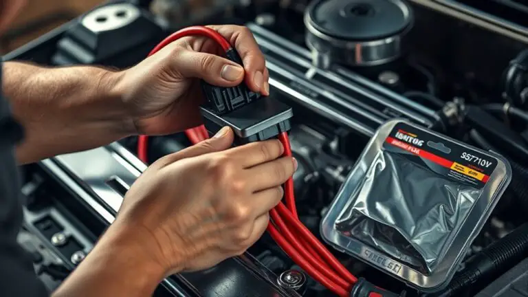
Step-by-Step MAP Sensor Replacement Procedure
If you’re ready to swap in a new MAP sensor, start by locating the sensor and disconnecting the battery ground to avoid shorts. You’ll follow a concise, repeatable procedure that keeps the engine safe and your project moving.
- Remove electrical connector and carefully unseat the old MAP sensor, noting orientation.
- Compare sensor types to confirm compatibility, then install the replacement with the correct gasket or seal.
- Reattach the connector, torque mounting screws to spec, and reconnect the battery ground, testing for a clean, steady signal.
Tips to prevent sensor failure: handle connectors gently, avoid overtightening, and verify wiring harness integrity. When you swap, you’ll notice the absence of rough idle or white smoke that once signaled a failing map sensor types issue. This approach keeps the repair focused and avoids overthinking, delivering a precise, practical replacement that restores proper engine management without extra drama.
Reconnecting and Calibrating the System
Once the new MAP sensor is seated and wired, reconnect the battery ground and start the engine to confirm basic operation; if any codes appear, clear them and recheck connections. With the engine idling, monitor live data and verify MAP readings respond to throttle input smoothly. If readings are inconsistent, recheck sensor orientation and vacuum hoses for leaks or kinks, then reset baseline values. Perform system calibration by following your vehicle’s service data, ensuring the PCM learns the new sensor’s range properly. Make small throttle maneuvers and watch for stable idle and proportional response. If the fuel trims look skewed, allow the system a brief adaptive period and observe changes after a few cycles. Document any adjustments you make and compare them against expected ranges. You want predictable behavior, so tighten sensor adjustments until readings align with manufacturer specifications and you’re confident the system calibration reflects reality. Maintain a clean, organized workspace to prevent gremlins.
Post-Replacement Checks and Road Test
With the new MAP sensor installed and basic checks complete, it’s time to validate the system under real-world conditions.
- Post replacement maintenance: monitor fuel trims, check for steady idle, and confirm no new codes appear during a short drive.
- Performance evaluation: test acceleration, highway cruising, and uphill pulls to ascertain the sensor reports accurate MAP readings and the engine avoids hesitation.
- Road test protocol: run through a representative route, note any surge, misfire, or smoke behavior, and log coolant and oil temperatures to catch lurking issues.
During the test, stay observant: watch the exhaust for smoke, listen for unusual noises, and verify the dashboard indicators stay off unless the engine demands adjustments. If any anomaly appears, pull over safely, recheck sensor connections, and clear codes if needed. This final pass confirms reliability, supports post replacement maintenance, and validates performance outcomes for continued freedom on the road.
Frequently Asked Questions
Will Replacing the MAP Sensor Affect Other Engine Sensors?
Will replacing the MAP sensor affect other engine sensors? Practically, it can, but typically only if you introduce contamination or an improper reset. If you install a compatible MAP sensor and clear any adaptives, sensor performance impact is minimal. MAP sensor compatibility matters, so choose a genuine part. You’ll likely notice steady readings, stable fuel trim, and smoother idle. Stay cautious: avoid dirt, torque specs, and re-learn if your ECU prompts it.
How Long Does a MAP Sensor Replacement Typically Take?
Typically, a MAP sensor replacement takes about 30 to 60 minutes, depending on your vehicle model and access. You’ll remove the old sensor, install the MAP sensor installation with proper sealing, and reconnect harnesses. While you’re at it, perform quick troubleshooting MAP issues to confirm the fix. Check for fuel trims and vacuum leaks after testing. Keep it practical: work methodically, stay organized, and you’ll regain reliable performance without unnecessary downtime.
Can I Drive With a Faulty MAP Sensor?
You can’t safely drive long-term with a faulty MAP sensor. It can cause faulty performance and erratic idling, poor fuel economy, and increased emissions. If you notice sensor symptoms like check engine light, rough starts, or white smoke from exhaust, pull over and diagnose. Driving may worsen damage. Seek a proper repair promptly, and replace the sensor before continuing, ensuring your system operates within designed tolerances and your freedom isn’t compromised.
Are Aftermarket MAP Sensors Reliable for My Vehicle?
To answer: aftermarket map sensors can be reliable if you choose quality brands and verify sensor compatibility with your vehicle. You’ll want to trust reputable sellers and avoid ultra-cheap options. Think of it as shopping for any essential part—do your homework. You’ll compare specifications, confirm correct voltage, and verify mounting and plug compatibility. If you find consistent reviews and solid warranties, your aftermarket choice should serve you well for practical, freedom-loving driving.
Should I Reset the ECU After Replacement?
Yes, you should reset the ECU after replacement. An ECU reset helps clear learned fuel trims and adapts to the new MAP sensor, so you’ll see accurate fueling and smoother idle. It supports ECU reset benefits by reinitializing sensors and pattern learning. After resetting, drive normally to complete the diagnostic cycle and allow the PCM to recheck sensor data. If issues linger, pull codes for diagnostic trouble, then address them promptly.