Step-By-Step: Using a Manufacturer-Level Scan Tool to Diagnose Complex Electrical Gremlins
A manufacturer-level scan tool lets you go deeper than consumer gear, so you start by establishing a solid baseline — note engine state, temps, and battery voltage under known-good conditions. Decode OEM codes with official procedures, then map them to likely subsystems. Watch live data streams, correlate sensor trends to system behavior, and chase root causes rather than symptoms. Follow a disciplined, stepwise workflow with repeatable tests, logging every finding. If you keep going, you’ll master the full diagnostic arc.
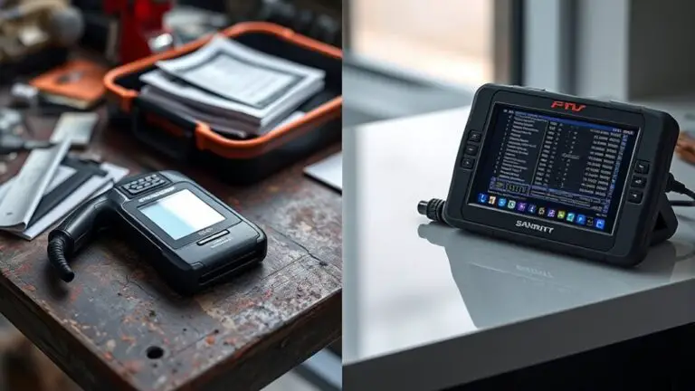
Understanding the Difference: Manufacturer-Level Scan Tools vs. Consumer Scanners

Manufacturer-level scan tools are designed for professional diagnostics and service tasks, offering deeper access to a vehicle’s systems than consumer scanners. You’ll notice access to advanced controllers, specialized routines, and real-time data streams that aren’t exposed by entry-level devices. This distinction matters when you’re seeking precise fault isolation, as manufacturer tools present vendor-specific terminology, parameters, and test modes calibrated for engineers. You’ll interact with dashboards that map to engineering documentation, enabling you to verify sensor integrity, actuation timing, and communication protocols with minimal ambiguity. While consumer scanners provide broad fault codes and cosmetic insights, they can mask root causes behind generic prompts. By understanding the difference, you preserve autonomy: you select the right tool for the task, restricting guesswork and accelerating repairs. In short, manufacturer tools empower you to diagnose with confidence, whereas consumer scanners offer baseline visibility suitable for routine maintenance and casual troubleshooting.
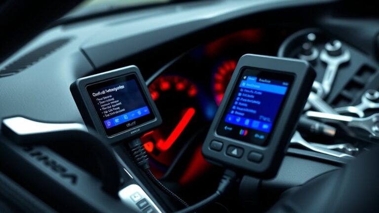
Baseline Setup: Establishing a Trustworthy Reference Point
Baseline setup starts by defining a trustworthy reference point you can consistently return to during diagnostics. You establish a controlled baseline using repeatable conditions and documented criteria, not guesswork. This baseline acts as your compass when gremlins surface and the tool shows divergent values. To execute baseline verification, you systematically record key sensor readings, electrical parameters, and system states under known-good conditions. Maintain consistent vehicle state: engine off or running, ambient temperature within a defined range, and battery voltage within spec. Use the same test sequence and data windows each time you measure. Reference calibration should be performed with calibrated adapters, traceable sources, and the latest software offsets applied. Document timestamps, tool versions, and any vehicle variability that could influence readings. With this solid reference in place, you differentiate true faults from transient noise, accelerating diagnostics and preserving your freedom to act decisively rather than chase noise.
Navigating Oem-Specific Codes: Decoding With Confidence
OEM-specific codes can be opaque at first glance, but you’ll reveal clarity by mapping each code to its OEM matrix and error tree. Start with a trusted reference list, verify the code against symptom context, and confirm with live data to avoid misinterpretation. This approach builds confidence as you decode codes with precision and methodical checks.
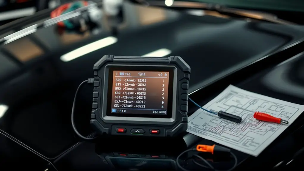
Decoding OEM Codes
Decoding OEM codes requires a systematic approach, because these codes are specific to each manufacturer’s diagnostic language and can vary widely from one vendor to another. You’ll map codes to root causes by aligning code types with documented OEM procedures, then cross-checking against known failure patterns. Begin with OEM code types you encounter, noting whether they’re P-CAN, generic, or manufacturer-specific, and catalog their meanings alongside fault context. Next, apply diagnostic procedures that correlate to each code and target the most probable subsystem first, reducing guesswork. Preserve traceability by recording codes, vehicle model, month of manufacture, and software level. Maintain a disciplined filter: don’t chase symptoms; chase data. With precision, you’ll decode efficiently, reserve time for verification, and build a reliable repair plan without ambiguity.
Confidence With OEMS
Guiding through OEM-specific codes with confidence starts by embracing the nuance that each manufacturer uses its own diagnostic language, yet a disciplined approach keeps outcomes consistent. You’ll build trust by validating codes against known failure modes, not just the number shown. Treat OEMs as distinct dialects within a shared diagnostic framework, mapping their terms to universal symptoms. Prioritize data integrity: confirm timestamps, cross-check freeze frames, and reproduce faults when possible. This mindset strengthens OEM Reliability and narrows diagnostic gaps quickly. Maintain a consistent workflow: compile code history, apply fault-tree logic, and document corrective actions with precise measurements. Your confidence grows as accuracy improves, driven by disciplined interpretation rather than guesswork, ensuring Diagnostic Accuracy across brands and delivering transparent, reproducible results.
Interpreting Live Data Streams: From Sensor Readings to System Behavior
You’ll start by identifying live data patterns that indicate normal versus anomalous behavior, then map how sensor readings relate to overall system performance. Next, you’ll link specific sensors to expected functions, building a clear sensor behavior map you can reference during diagnostics. Finally, you’ll examine system-wide correlations, tracing how shifts in one domain can signal broader interactions and impact.
Live Data Patterns
Live data patterns reveal how sensor readings map to system behavior in real time. You’ll examine raw streams, then translate fluctuations into meaningful actions. Focus on consistent baselines, note deviations, and track correlations across channels. Use live data analysis to identify which parameters move together under varying loads, and which ones lag or diverge during faults. Prioritize sequence and timing: simultaneous spikes, phase shifts, and transient bursts often signal root causes rather than symptoms. Apply data pattern recognition to distinguish normal cyclic behavior from anomalies, avoiding over-interpretation of single-point outliers. Document patterns with explicit thresholds, and verify consistency through repeats. Maintain disciplined filtering, filter out noise, and validate findings against known system models, ensuring conclusions remain concise, actionable, and repeatable.
Sensor Behavior Mapping
Sensor behavior mapping translates raw sensor readings into an actionable model of system performance, showing how parameter changes correspond to operating states. You’ll translate streams into patterns that reveal cause-and-effect, then validate with repeatable tests.
- Establish baselines using sensor calibration techniques to set reference points and guarantee repeatability.
- Track deviations with electrical signal analysis, distinguishing noise from meaningful shifts tied to state changes.
- Correlate sensor trends to known operating modes, documenting thresholds and hysteresis for quick diagnosis.
- Validate mappings by simulating edge cases and verifying that observed responses match expected behavior under load and fault conditions.
System-wide Correlations
System-wide correlations connect individual sensor streams to the broader behavior of the system, turning raw readings into a coherent picture of how components interact under real-time conditions. You’ll track how simultaneous signals—voltage, current, temperature, and duty cycles—coalesce into identifiable patterns. Start by aligning timestamps across channels, then compare onset, peak, and recovery moments to confirm causal links. Look for consistent delays revealing control logic or feedback loops, and note divergences indicating potential electrical anomalies. Map correlations to subsystem boundaries, distinguishing sensor-driven variance from actuator-driven responses. Document thresholds, hysteresis, and saturation points that define normal vs. abnormal system interactions. Maintain discipline in data labeling and filtering to preserve actionable insight, avoiding overinterpretation while remaining vigilant for hidden faults.
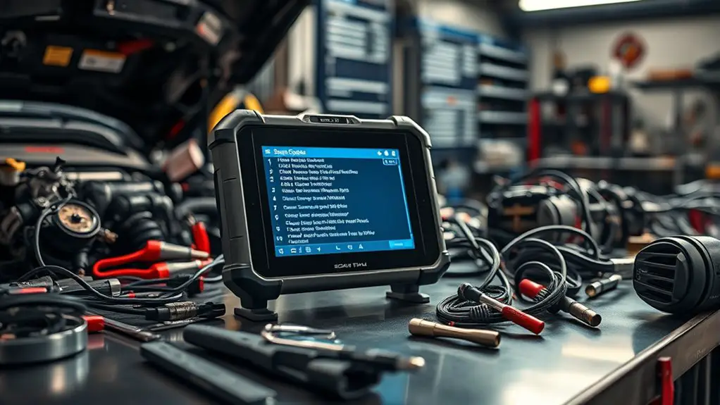
Workflow Essentials: Step-by-Step Diagnostics for Complex Gremlins
Diagnostics rarely improve by guesswork; instead, a disciplined, step-by-step workflow guarantees you pinpoint gremlins efficiently. You’ll rely on diagnostic flowcharts and structured electrical troubleshooting to stay purposeful, not paralytic. Follow a logical sequence, verify assumptions, and document findings as you go.
Diagnostics are sharpened by a disciplined, step-by-step workflow—no guesswork, just structured, repeatable tests.
1) Define the failure: observe symptoms, reproduce safely, and note conditions under which the issue appears.
2) Isolate circuits: map the path from power to ground, test at logical checkpoints, and rule out cascading faults.
3) Validate components: perform targeted tests on sensors, modules, and wiring harnesses with repeatable criteria.
4) Confirm resolution: re-create the scenario, compare to baseline, and ascertain no new anomalies arise.
This approach respects your need for freedom within discipline, delivering reliable results without guesswork. Embrace concise notes, repeatable tests, and clear pass/fail criteria to drive electrical troubleshooting with confidence, using diagnostic flowcharts as your compass.
Common Pitfalls and How to Avoid Them
Even with a solid workflow, you’ll encounter traps that can derail progress if you’re not prepared. First, avoid assuming all data is correct; sensor IDs and codes can mislead if you don’t verify with live context. Rely on corroborating readings across channels rather than a single metric. Next, don’t overlook grounding and power integrity. A flaky ground can produce phantom faults that waste troubleshooting strategies. Always confirm the baseline conditions before testing, then reproduce symptoms safely to isolate variables.
Be precise in interpretation: correlate scan data with vehicle behavior, not memory. Resist the urge to rush diagnoses with guesswork or generic fixes. Document every step, including failed attempts, to uncover patterns that reveal true faults. Practice disciplined data filtering—remove noise, focus on anomalous trends, and sequence tests logically. Finally, maintain a clear boundary between “wow, that’s interesting” and “that’s the fix.” Recognize common mistakes early to protect time, equipment, and confidence.
Time-Saving Tricks for Efficient Troubleshooting
Here are quick, proven techniques to cut wasted time when troubleshooting: start by prioritizing symptoms that recur across multiple systems, then confirm baseline conditions fast so you can reproduce issues safely and repeatedly.
- Prioritize cross-system symptoms to focus your diagnostic effort on root causes, not symptoms.
- Establish fast baselines with repeatable tests, ensuring consistent results for reliable comparisons.
- Use non-destructive diagnostics first, reserving invasive checks for when data demands it.
- Document findings succinctly as you go, building a reusable troubleshooting framework for future sessions.
These tips optimize troubleshooting efficiency and create reliable diagnostic shortcuts you can lean on under pressure. By tightening your workflow, you reduce guesswork and increase confidence in each decision. Remember, precision beats speed if it sacrifices accuracy; speed and accuracy together deliver true freedom in diagnostics. Stay disciplined, measure outcomes, and refine your method with every vehicle you assess.
Applying the Methodology Across Vehicle Platforms and Systems
Across different vehicle platforms and systems, you’ll apply the same disciplined methodology you used for quick, cross-system trouble spots, but with platform-specific calibrations and interfaces. You approach each platform with a clear plan: identify core data points, verify sensor health, and isolate the module driving the fault. This means recognizing system variations and adapting test sequences without abandoning the core diagnostic logic. Begin with a baseline scan to establish expected ranges, then map fault codes to likely subsystems, considering how controllers communicate over CAN, LIN, or FlexRay. When you encounter platform compatibility quirks, leverage vendor-specific menus and data streams to confirm symptoms, not just codes. Document all steps, noting divergences in wiring, grounding, and power architecture. You’ll maintain confidence by applying the same rigor, while respecting the unique interfaces each platform presents. The result is reliable fault isolation across platforms with minimal ambiguity and maximal clarity.
Frequently Asked Questions
How Do OEM Tools Differ From Dealer-Only Scanners?
OEM tools differ mainly in scope and access. You’ll get OEM tool features that are broad, factory-grade diagnostic paths, software updates, and vehicle coverage that general dealer scanner limitations don’t match. You’ll notice dealer scanners are restricted by VEPs, access controls, and subscription gaps, reducing depth. Think of it as a specialized toolset vs a generalist. You’ll gain greater data fidelity, faster bi-directional controls, and more robust reflashing options when you choose OEM capabilities.
Can These Tools Diagnose Intermittent Electrical Gremlins?
Yes, these tools can diagnose intermittent electrical gremlins, though results depend on data capture and test setup. You’ll monitor live sensor streams, freeze frames, and fault codes to pinpoint intermittent issues. Use long-term logging, reproducible scenarios, and baseline comparisons to separate noise from real faults. Systematically verify with multi-point checks, wiring integrity, and module diagnostics. Your approach should be precise, methodical, and oriented toward freedom: reliable conclusions, not guesswork, in electrical diagnostics.
What Safety Steps Before Connecting High-End Scanners?
Like a calm lighthouse, you should start with safety steps before connecting high-end scanners. You must observe safety precautions, wear eye protection, disconnect power when possible, and ground yourself to prevent static discharge. Inspect cables for wear, secure the vehicle, and follow OEM guidance. Maintain your tools with care, performing scanner maintenance after use. Keep personal autonomy intact by staying methodical, documenting steps, and never bypassing safety for speed.
Do OEM Codes Have Universal Meanings Across Brands?
No, OEM codes don’t have universal meanings across brands. You’ll find OEM code interpretation varies, with brand specific nuances that affect interpretation, troubleshooting, and repair steps. You should cross-check the manufacturer’s documentation, use the same tool as the brand, and verify codes against known fault trees. You’ll gain clarity by documenting how each code maps to subsystem behavior, then apply diagnostic steps consistent with the tool’s guidance and your vehicle’s service bulletin references.
How Reliable Are Live Data Readings in Aging Vehicles?
Live data readings are only as reliable as the sensor health and the tool you trust. When you test an aging vehicle, live data accuracy declines with wear, loose connections, and brittle harnesses, so expect noise, intermittent gaps, and delayed responses. The better you verify, the more you learn: diagnose live data critically, cross-check with multiple channels, and document patterns. You’ll gain freedom by mastering aging vehicle challenges with disciplined, methodical checks.