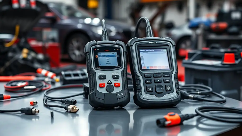
Tool Comparison: Budget Vs Professional for Diagnosing Noisy CAN Bus
When diagnosing a noisy CAN bus, you’ll get faster, more reliable results with a professional-grade toolset that balances timing precision, deep decoding, and robust filtering versus a budget option that trades fidelity for lower upfront cost. Expect higher sampling rates, deterministic triggers, and clearer causality trails from professional tools. Budget gear may save money short term but risks missed glitches and poorer long-term reliability. If you keep exploring, you’ll uncover how to choose between them for your setup.
Core Capabilities Dictionary
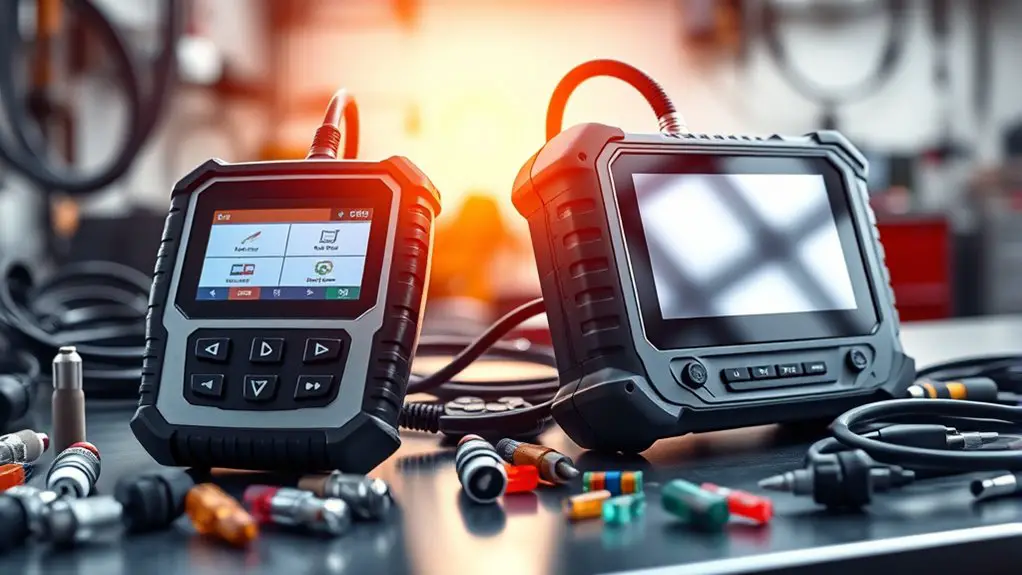
A Core Capabilities Dictionary defines the essential functions and measurements that underlie effective CAN bus diagnostics. You’ll use this dictionary to map tool behavior to measurable outcomes, ensuring reproducible assessments. Begin with core functionality evaluation: identify the minimum set of features a tool must provide to detect, quantify, and classify bus anomalies. Include frame timing accuracy, error counters, and baud rate adaptability as current benchmarks. Next, specify diagnostic tool specifications: data capture rate, trigger capabilities, filter options, and export formats. Define acceptable latency, retention, and sampling depth that preserve diagnostic fidelity under noisy conditions. Establish criteria for interoperability with standard CAN protocols (CAN, CAN-FD) and logging schemas, plus secure, auditable operation. Require clear, deterministic reporting: timestamps, event codes, and actionable recommendations. Document validation procedures, including reference test signals and repeatability checks. Finally, align these specifications with risk assessment, ensuring you can justify tool selections based on quantified reliability and the targeted diagnostic scope.
Signal Integrity Across Tools
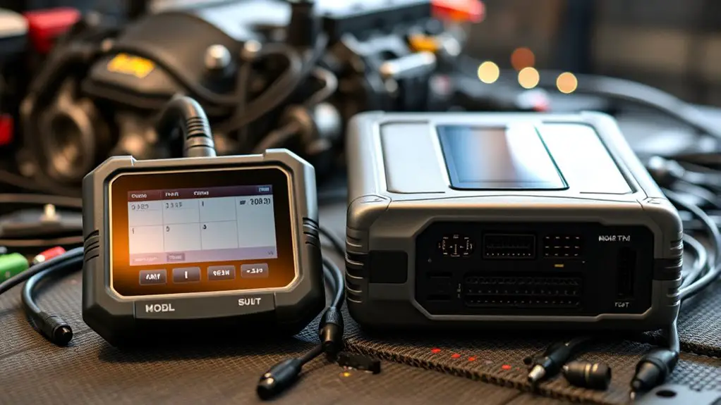
To compare signals across tools, you’ll anchor on how each instrument preserves waveform integrity from the CAN bus to the analyzer’s capture buffer. You’ll assess amplifier linearity, impedance matching, and cable loss, noting where signal quality degrades. Look for consistent differential signaling, minimal reflection, and tight rise times that reflect real bus conditions. Compare how each device handles noise gating, grounding strategies, and common-mode rejection, since these affect the fidelity of captured events. Focus on calibration procedures, traceability, and how measurement limits relate to your diagnostic goals. Evaluate time-domain stability as you shift from budget to professional hardware, ensuring that observed anomalies aren’t artifacts of the tool chain. In practice, you’ll emphasize robust tool selection that preserves true CAN dynamics without amplifying aliasing or jitter. Clear, reproducible results depend on maintaining clean signal paths and documenting verification steps for credible analysis.
Timing Precision and Sampling Rates
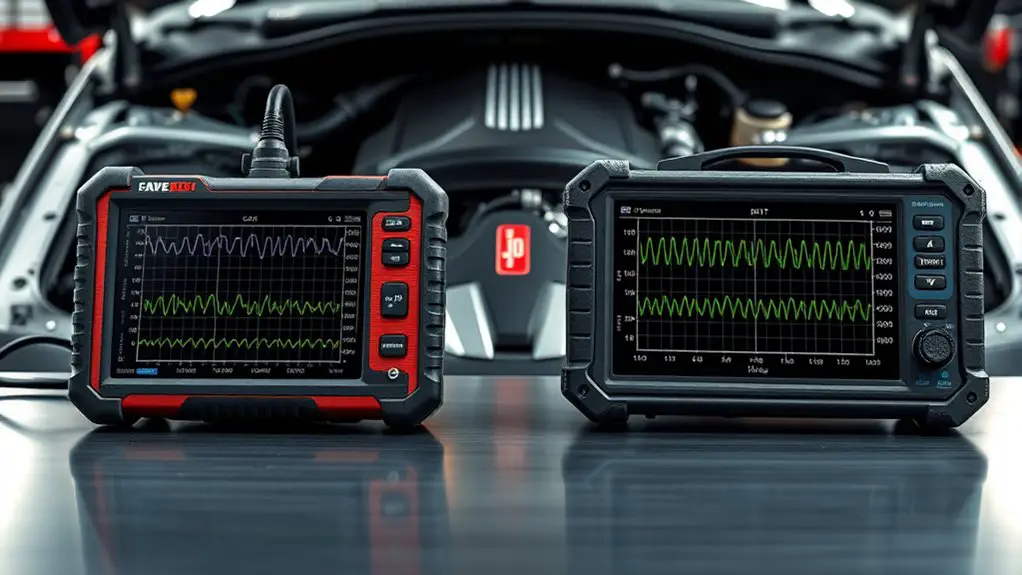
You’ll see that sampling rate directly governs the temporal granularity of CAN event capture, influencing both observable jitter and the accuracy of frame timestamps. Tradeoffs emerge between higher timing resolution and the data bandwidth or storage required to sustain it, so you’ll assess whether your setup meets the needed precision without overburdening the system. With these points in mind, focus on how Sampling Rate Impact and Timing Resolution Tradeoffs shape your measurement strategy and diagnostic confidence.
Sampling Rate Impact
Sampling rate directly governs timing precision and the fidelity of CAN bus measurements; higher rates reduce sampling error and better capture transient events, but they also increase data volume and processing load. You’ll balance sampling resolution against practical limits, ensuring data accuracy without overwhelming hardware. In practice, choose a rate that preserves essential edge timing while maintaining usable bandwidth for analysis. Lower rates risk missed glitches; higher rates improve fidelity but demand more storage and CPU. Consider your tool’s capture window and trigger behavior to avoid aliasing. The goal is predictable, reproducible measurements, not maximal throughput. Table below contrasts impact factors you’ll weigh when selecting between budget and professional setups.
| Factor | Effect |
|---|---|
| Sampling rate | Alters resolution and data volume |
| Data handling | Drives storage and processing load |
Timing Resolution Tradeoffs
Even so, timing resolution is the core constraint that ties sampling rate to measurement fidelity: higher sampling rates sharpen edge timing and reduce jitter, while lower rates save bandwidth but permit aliasing and missed transients. You balance timing tradeoffs by aligning ADC or oscilloscope capabilities with CAN bus dynamics, recognizing that sub-microsecond events demand aggressive capture. Resolution challenges arise from jitter sources, sampling interval nonuniformity, and trigger latency, all of which degrade event ordering and bit-stuffing detection. In a budget tool, you’ll trade some resolution for practicality, accepting occasionally ambiguous edges while preserving overall visibility. Professionally, you push for synchronized clocks, oversampling, and post-processing to recover timing accuracy. In both cases, clarity of timing is essential for trustworthy fault isolation and repeatable diagnostics.
Filtering and Bandwidth Management
Filtering and bandwidth management are essential for reliable CAN bus diagnostics, enabling you to isolate relevant signals without overloading the analyzer. You’ll apply filtering techniques to suppress common-mode noise and high-frequency artifacts that do not carry diagnostic value. Start with simple, deterministic filters (RC, digital FIR) to preserve timing integrity while reducing aliasing risk. Match cutoff frequencies to your target message IDs and bit rates, then validate with known-good frames to avoid bias. Bandwidth considerations guide you to sample at an appropriate rate and avoid excessive data capture that muddies interpretation or taxes storage. Use decimation selectively, ensuring pacing remains faithful to real-time behavior on the bus. Document filter order, cutoffs, and timing penalties so you can reproduce results. Favor a modular approach: implement filters close to the data source, monitor CPU load, and adjust in small, traceable steps. This disciplined setup supports precise analysis without sacrificing operational freedom.
Triggering and Event Capture
Triggering and event capture are about defining when to start and stop data collection to guarantee you capture meaningful CAN bus activity without drowning in noise or irrelevant frames. You’ll set precise conditions that lock onto the events you care about, not every bit flip. Use triggering techniques that align with your diagnostic goals: frame ID thresholds, specific data payload ranges, edge changes, and timing windows that reflect typical bus behavior. Pair these with robust event capture strategies: dual-buffer logging, timestamp synchronization, and filter-based preselection to minimize wasted writes and maximize signal-to-noise ratio. Decide whether you need continuous capture for rare events or burst capture around detected activity, and implement memory and throughput safeguards accordingly. Validate triggers against known fault scenarios, then iterate thresholds to balance sensitivity with specificity. Document the trigger logic so teammates understand the capture rationale, ensuring reproducible diagnostics without sacrificing operating freedom.
Decode and Analysis Features
You’ll examine how Decode Capabilities Range covers raw frame decoding through higher-layer protocols, ensuring you can interpret identifiers, data lengths, and payloads across bus speeds. The Analysis Feature Set should be assessed for filtering, search, correlation, and fault-condition detection to support rapid root-cause work. Prioritize Usability & Workflow to gauge how smoothly you can navigate these tools during a noisy CAN session and integrate findings into a diagnostic report.
Decode Capabilities Range
Decode capabilities define how accurately and quickly a tool can interpret CAN frames, identify error states, and reconstruct message flows. You evaluate decode capabilities by testing how the instrument handles nominal traffic, error frames, and arbitration id variations. Decode accuracy reflects not just correct interpretation but the timing alignment between observed and actual frames, which matters under high bus load. Decode limitations describe boundaries imposed by sampling rate, trigger granularity, and buffer size, since abstraction layers may omit transient bits or rare error modes. You compare tools on how transparently they show interpreted signal chains and how faithfully they preserve cadence during bursts. In practice, expect a balance between speed, fidelity, and user control, enabling deliberate, freedom-driven investigation without sacrificing diagnostic rigor.
Analysis Feature Set
When evaluating an analysis feature set, you want tools that couple deep decode logic with structured, post hoc examination capabilities. You’ll assess how well the solution preserves raw frames, reconstructs bus timing, and flags anomalous sequences without masking root causes. Look for synchronized views that map CAN IDs to payloads, interpret error frames, and surface bit-timing violations in a repeatable, exportable format. A strong feature set enables cross-filtering by time, ID, and DLC, while offering automated anomaly detection and clear causality trails. Consider diagnostic capabilities: per-message diagnostics, bus state histograms, and correlation of faults to physical layers. In your feature comparison, prioritize deterministic results, reproducible filters, and concise reporting that supports confident troubleshooting.
Usability & Workflow
Usability & Workflow (Decode and Analysis Features) — this section examines how decode logic and analysis capabilities integrate into practical workflows, focusing on intuitive data access, navigable views, and reproducible steps. You’ll evaluate how the user interface supports rapid data discovery, traceability, and consistent results across sessions. Consider workflow efficiency: can decoding be started with minimal clicks, and can findings be replayed without reconfiguration? Usability testing should reveal the learning curve and customization options that matter to you, from adjustable dashboards to saved filter sets. Assess software integration with existing tools, data export formats, and signal tagging. Gather user feedback on feature accessibility, error handling, and documentation to guarantee a stable, repeatable process.
User Experience and Workflow
Effective tools streamline the process of diagnosing a noisy CAN bus by guiding you through a repeatable workflow, from data capture to analysis and reporting. You’ll notice that user experience hinges on consistent interaction patterns, predictable responses, and minimal cognitive load during setup. Workflow efficiency rises when the tool presents a clear sequence: configure logging, start capture, filter noise, quantify jitter, and generate actionable results. The user interface should be uncluttered, with logical feature navigation and unambiguous controls that reduce decision fatigue. Tool accessibility matters: cross‑platform compatibility, sensible licensing, offline support, and straightforward data import/export paths. Diagnostic speed benefits from lean data pipelines, real‑time visualization, and adaptive sampling that preserves detail without slowing you down. A shallow learning curve aids adoption, while robust user support shortens ramp time. Precise data visualization and transparent troubleshooting processes reinforce confidence in findings and repeatable outcomes.
Debugging Aids and Fault Isolation
Debugging aids and fault isolation require a structured toolkit that quickly distinguishes signal from noise and localizes issues to specific network segments, nodes, or frames. You begin with baseline measurements: clean, repeatable samples under known-good conditions to set reference thresholds for voltage, timing, and bit error rates. Then you apply layered debugging techniques that incrementally narrow the search: observe bus traffic with real-time decoders, verify termination integrity, and correlate timestamps across devices. Use selective logging to minimize data while preserving critical events, and deploy noninvasive probes to avoid perturbing traffic. Fault isolation hinges on reproducible fault detection, comparing symptomatic frames against expected CAN payload structures and CRCs. Maintain a disciplined hypothesis-driven workflow: hypothesize, test, confirm, and discard. Document findings with precise criteria and traceable steps. This approach supports rapid containment, reduces diagnostic wander, and aligns with both handheld and professional tooling strategies for durable, scalable fault resolution.
Budget Constraints Vs Long-Term Value
When you weigh budget constraints against long-term value, start with the upfront cost but quantify total ownership, including maintenance, calibration, and potential downtime. Short-term savings can mask higher long-term diagnostic risk if cheaper tools lack essential features or reliability. Consider a structured cost-benefit analysis that aligns tool capability with your CAN bus diagnostics requirements and expected lifespan.
Short-Term Cost Impact
Despite tighter budgets, choosing the right diagnostic tool for the CAN bus delivers tangible long-term value; a lower upfront cost may save today but incur higher maintenance and downtime costs later. You’ll measure short-term cost impact by comparing capital outlay, licensing, and training against reliability gains. Immediate benefits include faster fault isolation, clearer waveform analysis, and validated test vectors, reducing repeat tests and vehicle rework. Be precise about compatibility with your CAN topology, data rate, and fault models; cheaper options often require workarounds that add hidden labor. Document expected payback using a straightforward formula: upfront expense minus operational savings divided by maintenance avoidance. You’ll want a tool that scales with future needs, minimizing ad hoc add-ons and fragmentation. Favor modular, supported solutions to optimize total cost over several deployments.
Long-Term Diagnostic Value
Long-Term Diagnostic Value emerges when you balance budget constraints with enduring performance. You’ll assess total cost of ownership by weighing upfront spend against sustained diagnostic reliability. A budget tool may deliver quick wins, yet you’ll encounter higher marginal costs as it ages, requiring frequent replacements or manual workarounds. In contrast, a professional-grade solution often stabilizes long term expenses through robustness, better data quality, and consistent error detection. You’ll gain a clearer signal over time, enabling you to identify subtle CAN bus disturbances before they escalate, reducing downtime. This long term investment yields repeatable, trusted results, not sporadic reads. Your freedom to iterate designs hinges on reliable metrics, repeatable tests, and documented performance under varied conditions. Choose the option that preserves diagnostic reliability across evolving networks.
Real-World Scenarios and Best Practices
In real-world scenarios, diagnosing a noisy CAN bus requires a disciplined approach: start with clear symptom mapping, then verify hardware and software layers step by step. You’ll establish baselines: bus load, noise signatures, and frame timing aberrations. Use a controlled test plan, isolating power, grounding, and shielding effects before chasing elusive faults. Acquire repeatable measurements with calibrated tools, confirming that suspected interference isn’t a natural variation of traffic. Compare real world applications against lab expectations, documenting deviations and their impact on reliability. When tools disagree, prioritize root-cause analysis: verify termination, cable quality, transceiver health, and software filters. Apply practical experiences to set risk thresholds, so you can decide when a fix is hardware-backed or software-tuned. Maintain clear, auditable records to support engineering decisions under constraint. This mindset balances precision with autonomy, ensuring robust diagnostics without sacrificing the sense of freedom that fuels innovation.
Frequently Asked Questions
How Do Noise Sources Differ Between CAN 2.0 and CAN FD?
CAN 2.0 and CAN FD differ in bit timing and payload length, so noise sources impact them differently. You’ll see stricter timing margins in CAN 2.0, making common-mode spikes more disruptive, while CAN FD’s longer frames and altered arbitration reduce some collision sensitivity but expose you to extended peak voltages during data bits. Focus your Noise impact analysis on electromagnetic coupling, voltage rails, and bus termination, noting protocol differences that affect error counting and retransmission behavior.
Which Tool Excels at Post-Acquisition Statistical Analysis?
A tool that excels at post-acquisition statistical analysis is your best bet for precise insights. You’ll want statistical tools that support rigorous hypothesis testing, robust regression, and uncertainty quantification, paired with strong data visualization to reveal trends. Use these in concert with reproducible workflows. You’ll appreciate the clarity you gain when your data visualization communicates findings clearly, and your statistical tools back them with solid metrics. Embrace freedom, stay methodical, and validate with transparent analysis.
Can We Characterize Node-To-Node Jitter Under Load?
Yes, you can characterize node-to-node jitter under load. You’ll perform jitter analysis by measuring inter-arrival timing across nodes while applying defined load conditions, then compare histograms and phase plots to quantify dispersion. Use high-resolution timestamps, repeat trials, and compute metrics like PM jitter, RMS, and peak-to-peak. Document how load conditions shift timing skew, identify correlations with traffic patterns, and confirm findings with statistical significance for repeatable, rigorous conclusions.
Do Tools Support Automated Fault Injection for CAN Networks?
Did you know that automated fault injection runs can uncover up to 40% more CAN anomalies than manual tests? Yes—tools do support automated testing, including fault simulation, for CAN networks. You’ll find capabilities to inject bit errors, frame losses, and timing disturbances, enabling repeatable scenarios. When you pursue rigorous validation, rely on automated testing to guarantee repeatability, and use fault simulation to stress edges. This approach keeps your system robust under real-world jitter and load.
What Are Best Practices for Field Deployment With Limited Power?
In field deployment with limited power, best practices focus on power management and signal integrity. You’ll use energy-efficient hardware, schedule activity to align with available power, and implement low-power modes during idle periods. Minimize noise by proper grounding, shielding, and robust CAN termination. Validate voltage rails under load, monitor battery health, and use surge protection. Plan for redundancy, document wire routing, and test under real-world conditions to guarantee reliable, freedom-loving operation.

